Article

Integrating Flotation and Pyrometallurgy for Recovering Graphite and Valuable Metals from Battery Scrap

Department of Chemical and Metallurgical Engineering, School of Chemical Engineering, Aalto University, 02150 Espoo, Finland
*
Author to whom correspondence should be addressed.
Metals 2020, 10(5), 680; https://doi.org/10.3390/met10050680
Submission received: 29 April 2020 / Revised: 15 May 2020 / Accepted: 19 May 2020 / Published: 21 May 2020

Abstract

:
Since the current volumes of collected end-of-life lithium ion batteries (LIBs) are low, one option to increase the feasibility of their recycling is to feed them to existing metals production processes. This work presents a novel approach to integrate froth flotation as a mechanical treatment to optimize the recovery of valuable metals from LIB scrap and minimize their loss in the nickel slag cleaning process. Additionally, the conventional reducing agent in slag cleaning, namely coke, is replaced with graphite contained in the LIB waste flotation products. Using proper conditioning procedures, froth flotation was able to recover up to 81.3% Co in active materials from a Cu-Al rich feed stream. A selected froth product was used as feed for nickel slag cleaning process, and the recovery of metals from a slag (80%)–froth fraction (20%) mixture was investigated in an inert atmosphere at 1350 °C and 1400 °C at varying reduction times. The experimental conditions in combination with the graphite allowed for a very rapid reduction. After 5 min reduction time, the valuable metals Co, Ni, and Cu were found to be distributed to the iron rich metal alloy, while the remaining fraction of Mn and Al present in the froth fraction was deported in the slag.

1. Introduction

Since their commercial launch in 1991, lithium-ion batteries (LIBs) have become the dominant power source technology for a variety of electronic devices, from electric vehicles (EVs) to laptops, due to their superior electrochemical properties such as low self-discharge rate and high energy density [1]. The prospected demand of LIBs is expected to grow annually by 25% from 180 GWh in 2018 to 2600 GWh in 2030 [2]. The major driving factor for the growing demand is attributed to the transportation sector shifting to a low-emission fleet [2]. Consequently, an increasing demand of LIBs sets pressure on both the upstream processes (e.g., mining and refining) to extract raw materials and manufacture components, and downstream processes (e.g., second life and recycling) to maximize the recovery of secondary raw materials. Depending on the vehicle model, the LIB in an EV can make up 40% of the total costs, making it the most valuable component [3]. Therefore, the development of cost-efficient EVs is strongly focused on the value chain of batteries [3]. This in turn advocates for integrating recyclability as a design feature in the development phase [4].
The estimated lifetime of EV batteries is eight years during first life and five years for second life [5]. In consumer electronics, the lifespan is generally less than three years [6]. In 2035, 104 GWh of battery capacity is expected to reach end-of-life (EoL) [5], thus making the relatively large amount of metal reserves in EoL batteries attractive for recycling [7]. The benefits of recycling are multifold in terms of economics, regulatory perspective, securing raw material supply, new business creation opportunities [7], and environmental protection. Developing cost-efficient technologies and processes for LIB recycling is thus a necessity.
Despite this, only a small portion of the EoL LIBs are currently properly collected [8], while the vast majority are either hoarded in households, or end up in landfills [9]. This not only raises environmental concerns but is also a waste of valuable resources [10,11]. Additionally, the current EU Battery Directive 2006/66/EC in place does not sufficiently reflect the integration of the life cycle concept or the growing importance of LIBs as the recycling efficiencies are not defined for specific components or elements (e.g., Li and Co) [4,12].
The major components of a LIB include its casing, separator membrane, electrolyte, current collectors, a polymeric binder, and the active materials found in the electrodes. The active material usually comprises of graphite (anode) and some of various lithium metal oxides (cathode), and the mixture of the two is commonly referred to as black mass in industrial jargon [13]. The different components, relative amounts, and currently the most commonly applied materials were recently summarized by Velazquez-Martinez et al. [14]. Due to cost savings, supply risks [15], and increasing energy density requirements, cathode chemistries such as NMC 622 and 811, with less cobalt compared to NMC 111 or LCO chemistries, have entered the market. [7] In waste LIBs, the black mass hosts the elements with the highest economic value, and recovering these elements has, consequently, been the main focus of the industrial LIB recycling operations. [13,14] In the current state-of-the-art industrial LIB recycling processes, mechanical unit operations are first performed to recover the macroscopic components, and to separate the black mass fraction. The black mass is then further treated with either hydro- or pyrometallurgical processes (or a combination of both), and the valuables are recovered as either alloys or salts [16].
The main goal of the initial mechanical processing is to produce a sufficiently pure stream of black mass for the subsequent chemical purification, while providing a high enough throughput to ensure the economic profitability of the process. Therefore, a trade-off exists between the throughput and the grade/recovery of the valuables [17]. For example, it has been found that the different LIB components have distinctive particle size distributions after crushing, with the black mass consisting of considerably finer particles than the other components [17]. Consequently, after crushing the waste LIBs, screening is usually applied to separate the black mass in the underflow, while retaining the majority of the coarser components (Cu, Al, plastics) in the overflow [14,17]. However, due to incomplete liberation of the active particles [18], in order to increase the black mass recovery, the industrially applied sieve opening sizes are relatively large (~500 μm) [14]. This, however, results in quantifiable amounts of Al, Cu, and plastics reporting in the underflow. In addition, the Cu-Al rich sieve overflow has been shown to retain a considerable amount of the black mass [18].
Generally, it is seen that one of the advantages of applying pyrometallurgy in battery recycling is to minimize mechanical pre-treatment [19,20]. However, a relatively high fraction of metals is lost to the slag, which in some cases is further refined to recover metals or utilized by the construction industry [11,14,19]. These include metals, such as Li and Mn, with high oxide stability at high temperatures [21]. The industrial Umicore ValÉas™ and Sumitomo-Sony recycling concepts include pre-processing steps, such as dismantling and sorting, but no mechanical treatment [14]. In laboratory scale, Ren et al. [22] utilized two waste streams, namely (1) LIBs with Al cans and (2) copper slag from an industrial electric arc furnace cleaning process to produce an Fe-Co-Ni-Cu alloy and slag with fayalite (Fe2SiO4) and hernycite (FeAl2O4). Guoxing et al. [23] proposed a smelting reduction process at 1475 °C based on a MnO-SiO2-Al2O3 slag system resulting in a Co-Ni-Cu-Fe alloy and manganese rich slag to recover valuable metals from LIBs.
The EoL LIBs will start gradually returning to metals production as their amount increases and the recycling efficiency improves. Currently, the volumes are rather low and the most feasible way to recycle them is to feed them to existing metals production processes instead of developing and building new production plants. In this approach, the waste LIB would be partially functioning as a chemical reagent, applied as a secondary feed for the industrial process, and ideally eliminating the need for new chemical reagents. Consequently, decreasing the loss of valuable metals to the slag must be researched by introducing suitable mechanical pre-treatment. However, at the same time, new flexible processes should also be developed as the chemistries and compositions of the LIBs (or other batteries) are continuously developing.
In the present investigation, the aim is to integrate existing unit operations (sieving, grinding, froth flotation) and a unit process (EF slag cleaning) for recovering Co and Ni from the black mass fraction of LIB scrap and replacing the conventional reducing agent coke with graphite. Figure 1 shows a flowchart of the proposed process investigated in this article. In previous studies by the authors, the integration of battery recycling to nickel slag cleaning was reported successful for the first time [24]. Unlike these previous studies and many industrial pyrometallurgical processes for battery recycling, this approach emphasizes the importance of mechanical pre-treatment to minimize the loss of valuable metals to the slag. Coupling froth flotation to a pyrometallurgical unit process is introduced as a novel method for improving the LIB recycling efficiency, by allowing the selective recovery of leftover active materials from the Cu-Al rich sieve overflow, which is produced as a side stream during the initial mechanical processing of the waste LIBs. This approach is fundamentally different compared to the conventional black mass flotation studies [25,26,27,28,29,30] that have targeted to separate the anodic graphite in the froth phase, and the cathode active components in the tailings. Furthermore, the recovered froth flotation products are utilized as the only source of reducing agent in the nickel slag cleaning process replacing the fossil coke.

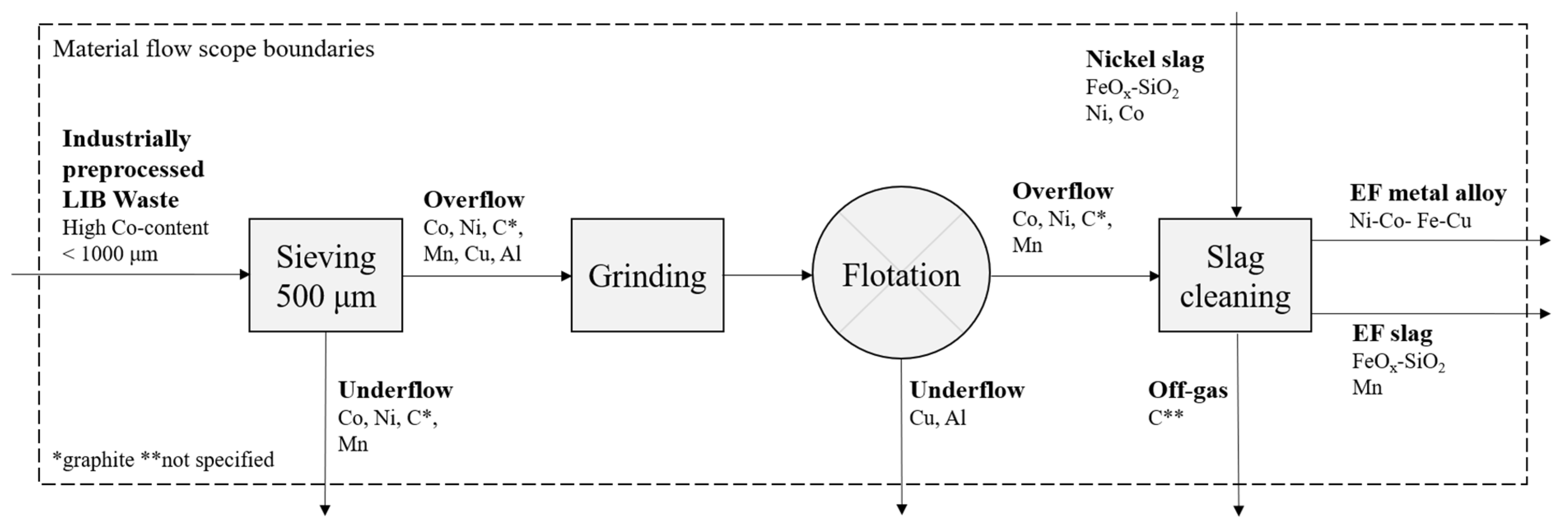
2. Materials and Methods

2.1. Froth Flotation

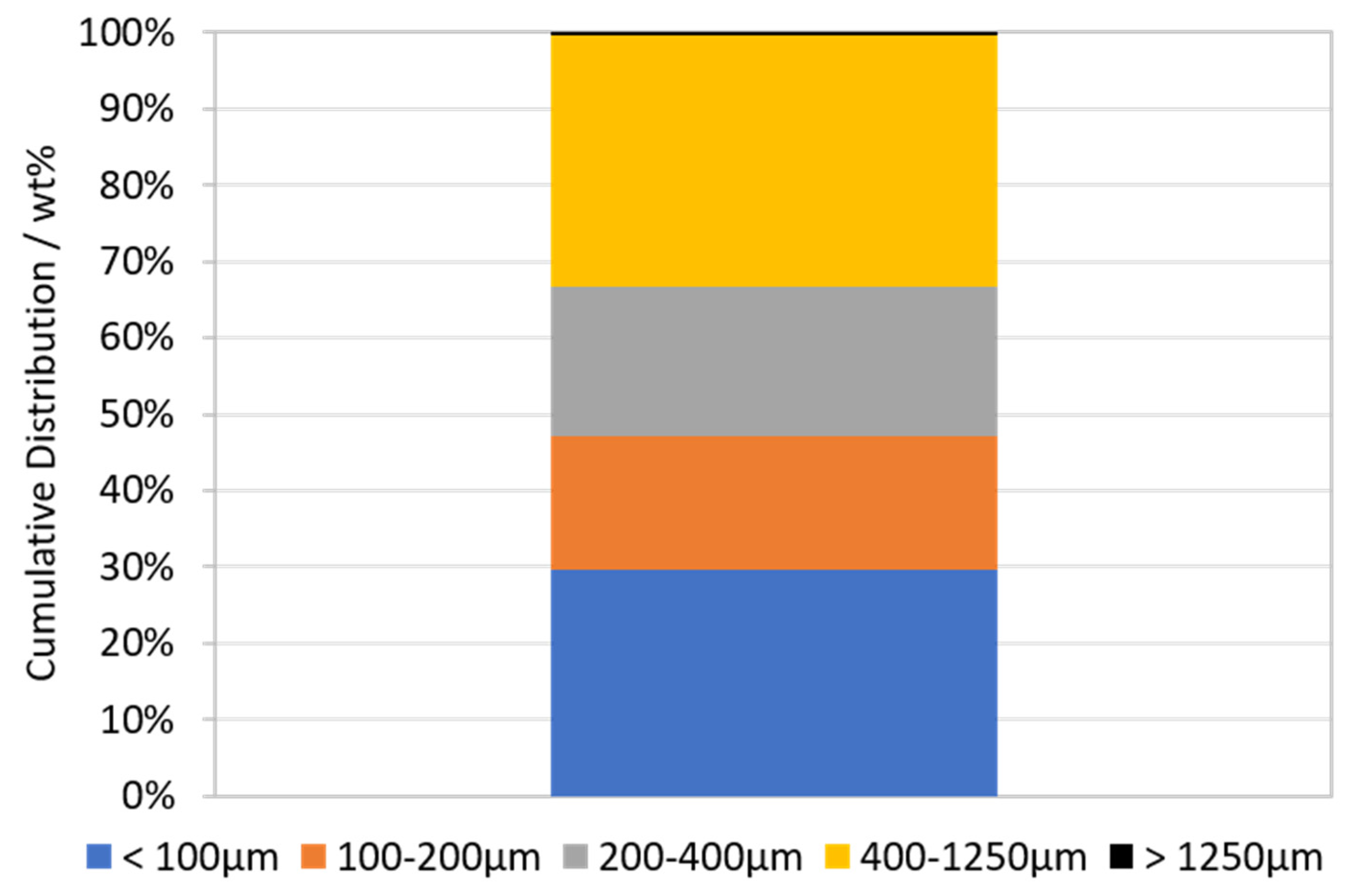
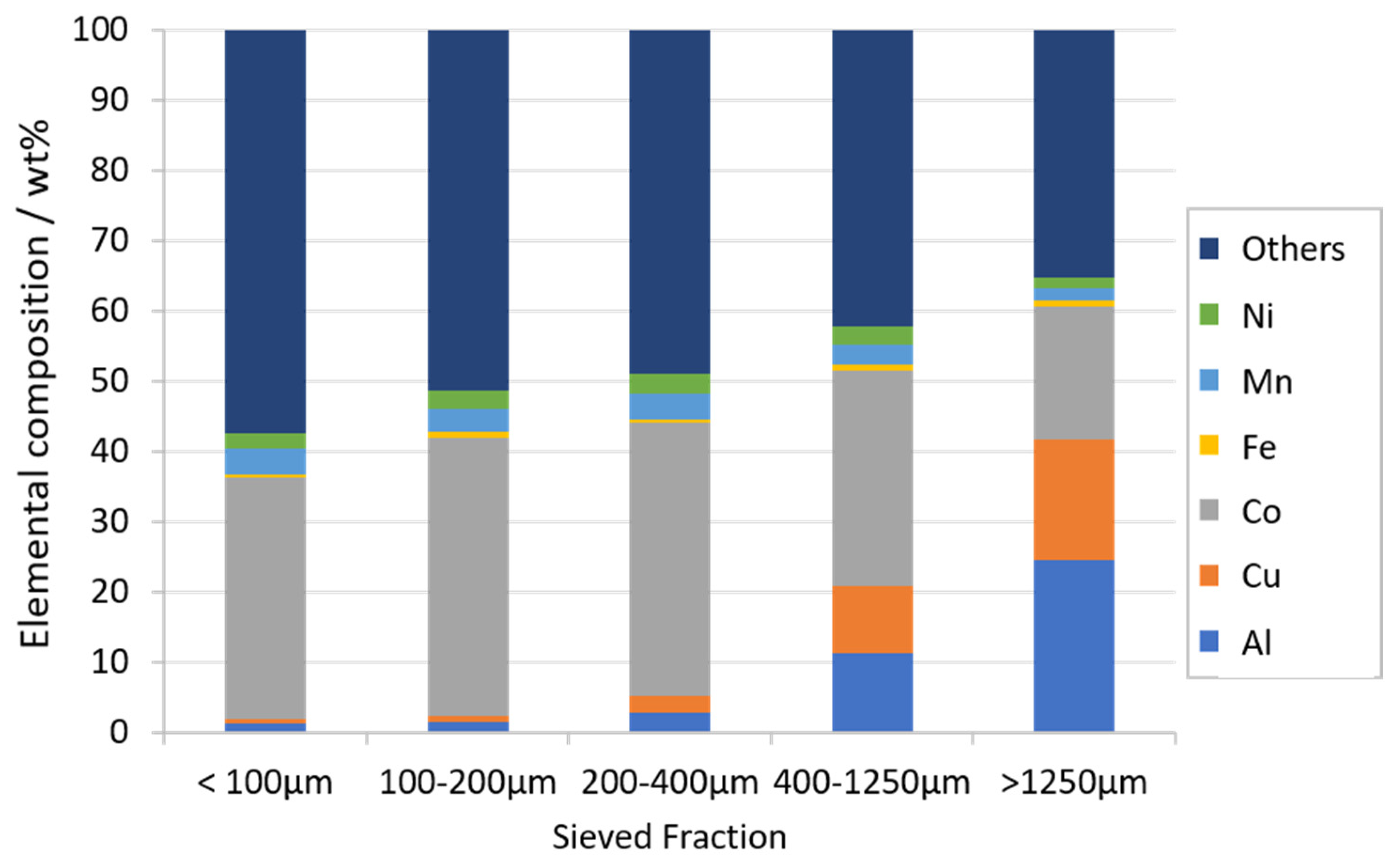
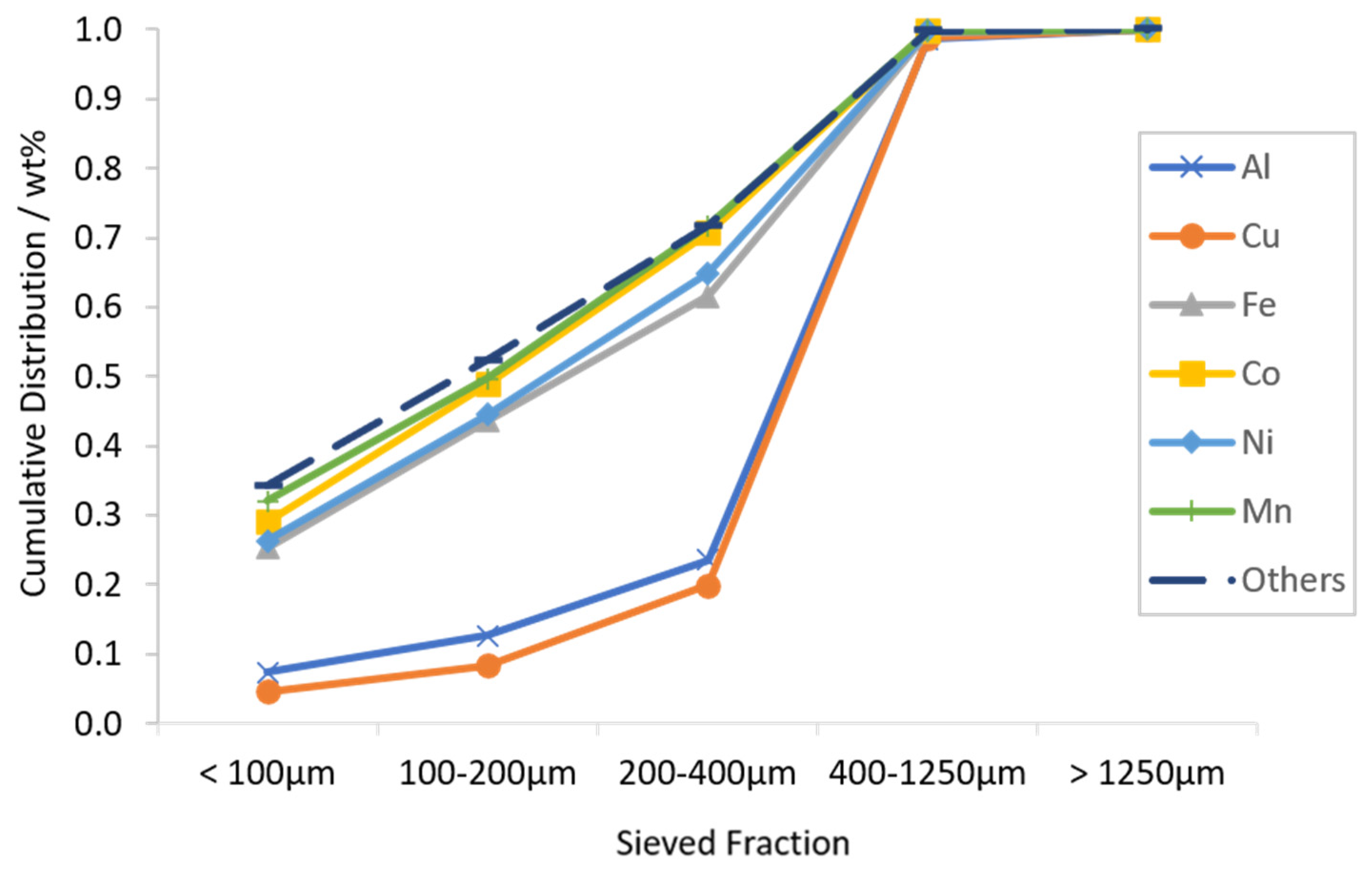
2.1.1. Sample Preparation and Characterization of the Waste Lithium Ion Battery Feed

LIB waste was obtained from Akkuser Oy (Nivala, Finland). In the industrial process, the waste LIBs are sorted, crushed, and sieved. Firstly, sorting was performed based on the cathode chemistry of the EoL LIBs, dividing the waste into fractions of high Co content and low Co content. The sorted fractions were subsequently crushed and sieved with a ca. 1000 μm sieve, and magnetic separation was applied to recover the steel casing materials. The present work utilized the underflow (<~1000 μm) of the industrially sieved high Co content fraction.
A sample of waste LIB of ca. 1.3 kg was taken and sieved in two batches for one hour. Sieving was performed using a vibratory sieve shaker (Fritsch Analysette 3, Idar-Oberstein, Germany) using a stack of four sieves with opening sizes of 1250 μm, 400 μm, 200 μm, and 100 μm. Since the exact sieve opening size of the industrial sieving process was unknown, the coarsest sieve selected was 1250 μm. To enable characterization with an X-ray fluorescence spectrometer (XRF, Niton XL3t, Thermo Fisher Scientific, Waltham, MA, US), a sample of the fractions with sizes > 100 μm was pulverized for 10 min in a disc mill (Retsch RS 200, Haan, Germany), and characterized with XRF for elements with atomic number ≥ 12.
As will be further discussed in Section 3, based on the composition results of the size fractions, the samples for froth flotation experiments were prepared by dry sieving ca. 190 g of LIB waste with a 500 μm sieve, at an amplitude of 5.5 mm over 10 min. The overflow (>500 μm) of this laboratory sieving process was used as feed for the flotation experiments.

2.1.2. Experimental Procedure of Froth Flotation

As a first conditioning step, the feed material was treated in a vibratory micro mill (Fritsch, Pulverisette 0, Idar-Oberstein, Germany), with an amplitude of 6 mm, and a batch size of ca. 13.33 g. The energy input provided by the micro mill under these conditions is low, as the objective of this step was solely to improve the particle liberation, by purifying the Cu/Al/plastic film surfaces, and not to further comminute the active materials. This procedure was repeated thrice to obtain a total feed mass of 40 g. In the experimental series, seven different milling times (0 min, 5 min, 10 min, 15 min, 20 min, 30 min, and 40 min) were studied.
After milling, the material was placed in a one-liter laboratory-scale flotation cell (Lab Cell—60mm FloatForce mechanism, Outotec, Espoo, Finland), and one liter of tap water was added. The solid-water suspension was then subjected to 1000 rpm of agitation for 3 min. After this period, 150 g/t of kerosene (collector) were added, allowing 3 min of conditioning under stirring. Finally, 8 ppm of MIBC (frother) were added, followed by two minutes of conditioning. Subsequently, air was fed to the cell at a flowrate of 2 L/min, marking the beginning of the flotation experiment. Throughout conditioning and flotation stages, the agitation was kept constant at 1000 rpm.
After the air flow was turned on, the system was given approximately 10 s to form a stable froth fraction, after which the froth was manually scooped at defined time intervals for a total of 25 min. To monitor the kinetics of the separation, froth products were collected into three different fractions, namely 0–1 min, 1–10 min, and 10–25 min from the beginning of the experiment. Since froth production was at its most hectic in the earlier stages of the experiment, for the 0–1 min fraction, the froth was scooped in a continuous fashion, for the 1–10 min fraction, froth was collected every 30 s, and for the 10–25 min fraction, sampling was carried once per minute. To maintain a constant froth height, tap water was added into the flotation cell as needed.
Each froth fraction was subsequently filtered and dried for 48 hours in a convection oven (Memmert UE400, Büchenbach, Germany). The drying temperature was kept at 40 °C, to avoid the formation of hydrofluoric acid (HF) via decomposition of any leftover electrolyte or other fluorine compounds. During all working stages of the flotation experiments, the laboratory atmosphere was monitored with a portable HF (g) detector (GfG Micro IV, Dortmund, Germany), but no peaks of HF release were recorded. This suggests that the majority of the electrolyte was already recovered during the industrial processing.

2.1.3. Characterization of the Flotation Products

The dry froth products and tailings were weighed, and the elemental compositions for atomic numbers ≥ 20 were determined by a portable XRF gun (Oxford Instruments, X-MET 5000, Abingdon, UK). To account for the heterogeneous nature of the LIB waste, five 30 s measurements were performed for each froth/tailings sample, and an average value was calculated. To improve the accuracy in the analysis of composition, inductively coupled plasma mass spectrometry (ICP-MS) was performed on selected samples, and a linear regression model was built based on the observed correlations, for each individual element of interest. The regression models were then used to adjust the results obtained with the XRF.
Based on the measured mass and the elemental compositions of the fractions, the elemental mass per fraction, head grade, cumulative grade, and cumulative recovery were calculated for each component of interest. Furthermore, separation efficiency (SE) values were calculated for Cu as shown in Equation (1) [31]:
S E = 100 C m ( c f ) ( m f ) f
where,
  • C 
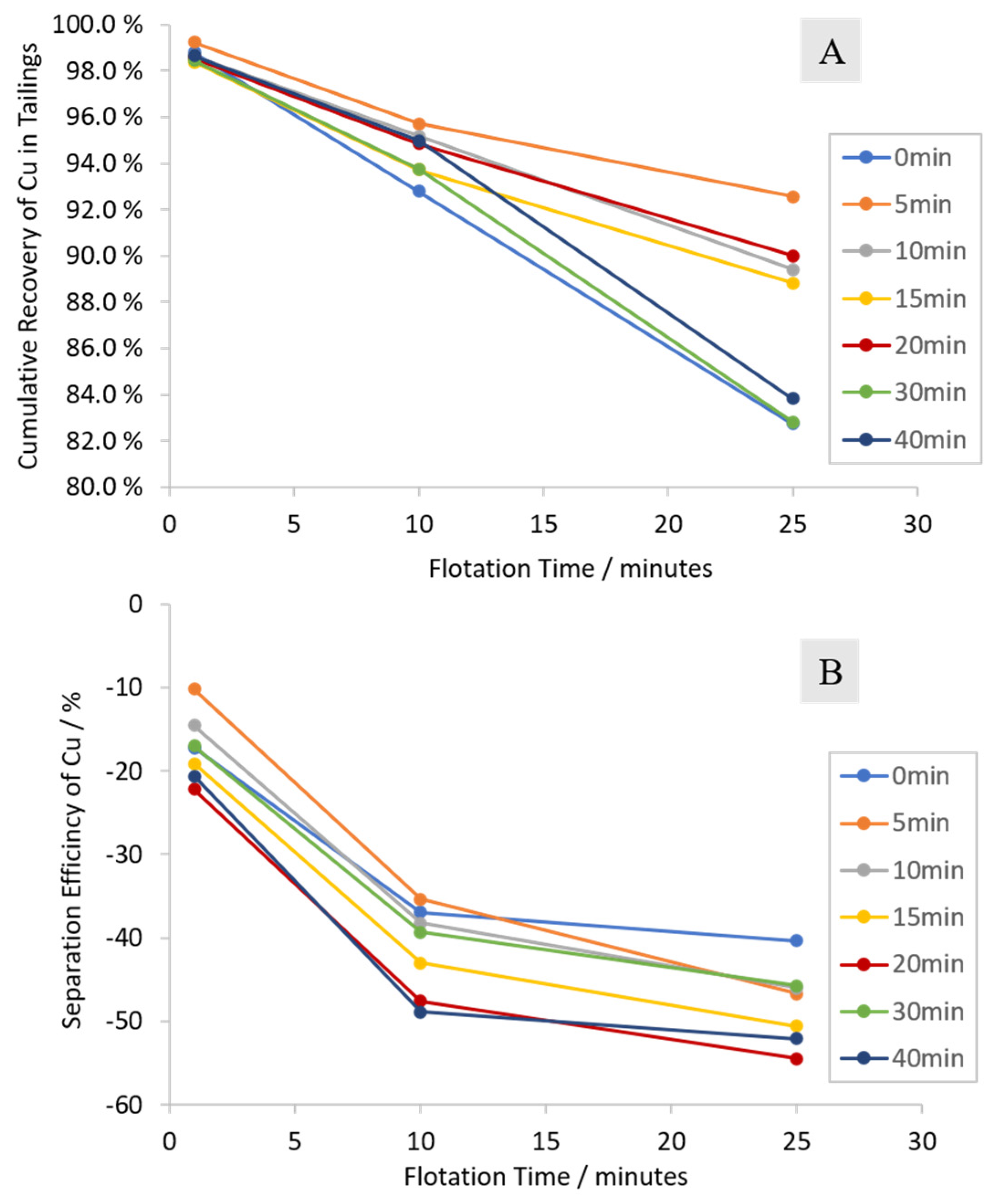
= Fraction of feed weight reporting to the froth at time t (1, 10, 25 min) [wt%]
  • m = Metal content of Cu in the mineral [wt%]
  • c = Fraction of Cu reporting to the froth at time t (1, 20, 25 min) [wt%]
  • f = Fraction of Cu reporting to the feed at time t (1, 10, 25min) [wt%].
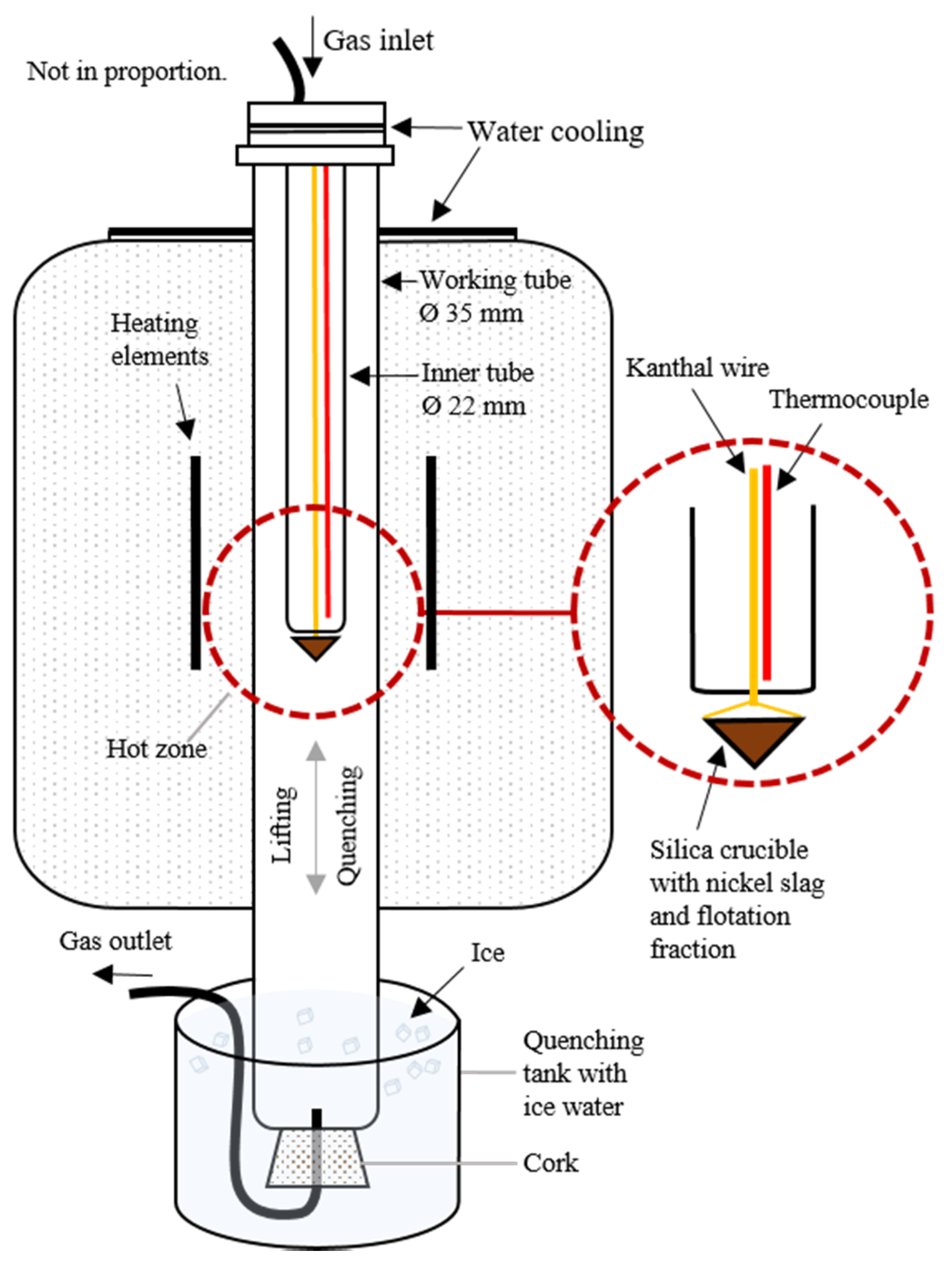
Since all Cu content in the waste LIB feed was assumed to be in a metallic phase, the value for m was assumed to be 100 wt%. The active materials, however, were assumed to be present in various chemistries (as discussed in Section 3), and determining a single m value for them would have thus been difficult. For this reason, SE values were not calculated for Co, Ni, and Mn.
Based on the results of the characterization, an optimal milling time was determined, and an additional flotation experiment was performed under the optimal parameters (as discussed in Section 3) to collect a sufficient amount of material for the subsequent nickel slag cleaning experiments.

2.2. Slag Cleaning

2.2.1. Materials

The slag was acquired from Boliden Harjavalta (Harjavalta, Finland). Table 1 shows the elemental composition of the slag, which was analyzed with X-Ray Fluorescence (XRF) spectrometry. Most of the metals in the slag were in oxidic form, and therefore they were converted into oxides. For iron, the oxidation state can be 2+ and/or 3+, so it was left in the metallic state. The sum in Table 1 is less than 100 wt% mostly due to the unknown amount of oxygen in iron oxide. Additionally, the slag contained entrained metallic or sulfidic droplets [24].
In order to investigate whether graphite from recycled LIBs could be used as a reducing agent in nickel slag cleaning, the battery material from the selected flotation fraction was added to the slag. Supposedly, this fraction should contain the highest amount of graphite and cobalt. The slag and flotation fraction were mixed in a mortar with a 4:1 ratio to ensure that there is excessive carbon available. The elemental composition of the starting mixture with slag and battery fraction from flotation for the experiments is presented later.

2.2.2. Experimental Procedure

The furnace settings and the experimental procedure for high-temperature heating and quenching were described in detail earlier [32,33]. The experiments were conducted in an LTF 16/450 single-phase vertical tube furnace (Lenton, Parsons Lane, Hope, UK). A schematic of the furnace can be seen in Figure 2. The furnace was equipped with four silicon carbide heating elements, an alumina working tube (Ø 35 mm ID, Frialit AL23, Friatec AG, Mannheim, Germany) and an inner tube (Ø 22 mm ID) installed inside the working tube to ensure the correct position of the sample in the hot zone. A Kanthal A1 wire (Ø 0.65 mm) was used in the experiments for lifting the sample to the hot zone.
The experiments were conducted in inert atmosphere with a gas flow rate of 400–500 mL/min argon (99.999% purity, AGA Linde, Espoo, Finland). The end of the working tube was sealed with a cork allowing gas to flow out of the furnace through a tube installed inside it. The silica crucible with the nickel slag and flotation fraction mixture was placed into a basket made of Kanthal wire. To ensure an inert atmosphere in the experiments, the furnace was flushed with argon gas for 15 minutes before lifting the sample to the hot zone from the cold zone. Time zero (t = 0) was set to be the moment when the crucible was lifted and positioned in the hot zone. The samples were held in the hot zone at 1350 °C and 1400 °C for 5, 10, 20, 30, and 60 min. The end of the working tube was immersed in ice water before the end of the contact time and after reaching full contact time, the cork was taken out and the Kanthal wire was pulled sharply upwards to release the basket with the sample to be quenched in ice water.
After quenching, the samples were dried, mounted in epoxy, ground, polished, and coated with carbon. The SEM-EDS (Scanning Electron Microscopy-energy Dispersive X-ray Spectroscopy) analyses were carried out at Aalto University Department of Chemical and Metallurgical Engineering with a MIRA 3 SEM (Tescan, Brno, Czech Republic) equipped with an UltraDry Silicon Drift Energy Dispersive X-Ray Spectrometer and NSS Microanalysis Software (Thermo Fisher Scientific, Waltham, MA, USA). An accelerating voltage of 15 kV and a beam current of 9.8 nA were used in the analyses. The counting time was set to 20 s per spectrum. The standards (Astimex Standards Ltd. Toronto, Ontario, Canada) in EDS analyses were as follows: pure metals (Co Kα, Cu Kα, Ni Kα, Zn Kα, Mg Kα, Mn Kα, Al Kα), quartz (Si Kα and O Kα), hematite (Fe Kα), marcasite (S Kα), calcite (Ca Kα), and sanidine (K Kα).

3. Results & Discussion

3.1. Characterization of LIB Waste

The size distribution of the industrially produced waste LIB sample used in this study is reported in Figure 3. As presented in the figure, the highest mass fractions are those at sizes <100 μm and 400–1250 μm with ca. 30 wt% each, whereas the middle size fractions represent around 20 wt% each. The fact that the fraction > 1250 μm only hosts 0.3 wt% of the total mass indicates that the industrial sieving was efficient.
For the most abundant elements (Fe, Al, Cu, Ni, Mn, Co), the elemental compositions of the sieved fractions are presented in Figure 4, as measured by XRF. Other components, including e.g., graphitic carbon and Li, are collectively represented by the “other” column.
The cumulative distributions of the main components are presented in Figure 5. From this figure, it is seen that Cu and Al report to the > 400 μm fractions, whereas Fe, Co, Ni, Mn, and other components are dominant in the finer fractions. For Cu and Al, this behavior is expected, as these metals likely originate from the large components in the LIBs, such as current collector plates and casing materials. However, it is noteworthy that both Al and Cu are also present in the finer fractions, as approximately 20 wt% of these elements are recovered in the fractions < 400 μm. Interestingly, Al is more abundant than Cu in all of the < 400 μm fractions, which could be explained by its presence in some cathode chemistries (LiNiCoAlO2). In any case, these results indicate that an industrial crushing process will result in fine-sized Al and Cu components, thus emphasizing the need for the LIB recycling studies to be conducted with real battery waste, instead of artificially produced anode-cathode mixtures, as has been the case in various publications [25,26,27,28,29,30]. Indeed, the presence of these metals in the black mass and its repercussion in subsequent metallurgical processes has been overlooked so far by other authors.
The cathode active components (Co, Ni, and Mn) are expected to report in the finer fractions, since these materials are applied as fine powders (<100 μm) in the electrodes of the battery. However, the fact that all of these components are also present in the size fractions > 100 μm suggests that the currently used combination of crushing and dry sieving is inefficient in separating the active particles. The majority (~70 wt%) of the Co, Ni, and Mn particles are carried on to the coarser fractions, possibly adhered on the surfaces of the coarser components (Al, Cu, plastics). This phenomenon is also reported in other studies conducted with industrial LIB waste [18].
Fe seems to follow a similar trend with the cathode active components, indicating that the waste battery feed might involve LIBs with Fe-based cathode chemistry (LiFePO4). Further evidence for the Fe content in the feed being at least partially of-cathodic-origin rather than as residue of casing materials is the fact that magnetic separation had been performed by the industrial operator for the separation of any metallic Fe. As the industrial operator claims to have sorted the waste LIB feed for high Co cathode chemistries only, the assumed LiFePO4-based Fe content is most likely either due to inefficiency in the sorting process, or the presence of mixed cathode chemistries.
The major constituents of the unidentified “other” materials are expected to be graphite (anode active material), carbon black (conductive additive), Li (cathode active material), F (PVDF), O (cathode active material), and polymers (PVDF and the separator films). The cumulative distribution of these materials seems to follow a very similar trend with Co, Ni, and Mn. Since the majority of the elements in the “others” fraction are associated with the active materials in the battery structure, they can be expected to be distributed in a similar manner with the cathode active elements.
Based on the cumulative distributions of the components, it can be argued that the dominant cathode chemistry in the waste LIB feed is most likely LiCoO2, including some LiNixMnyCozO2 variants (various NMC-ratios) and LiNiCoAlO2. Furthermore, it is likely that small amounts of batteries with LiFePO4 cathodes have ended up in the waste stream as well.

3.2. Flotation Experiments

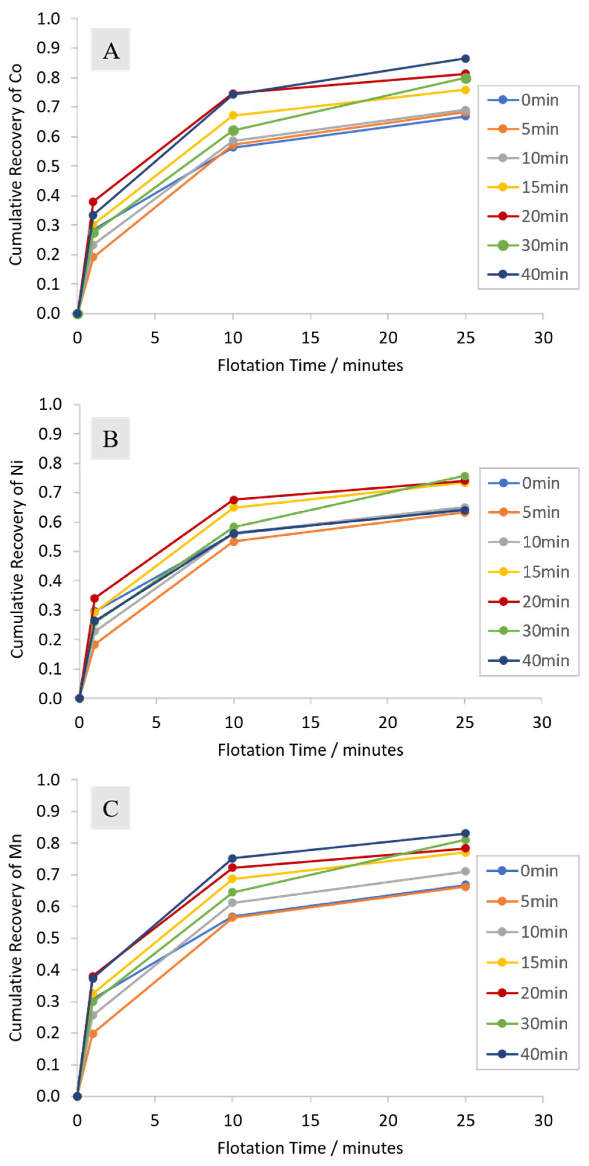
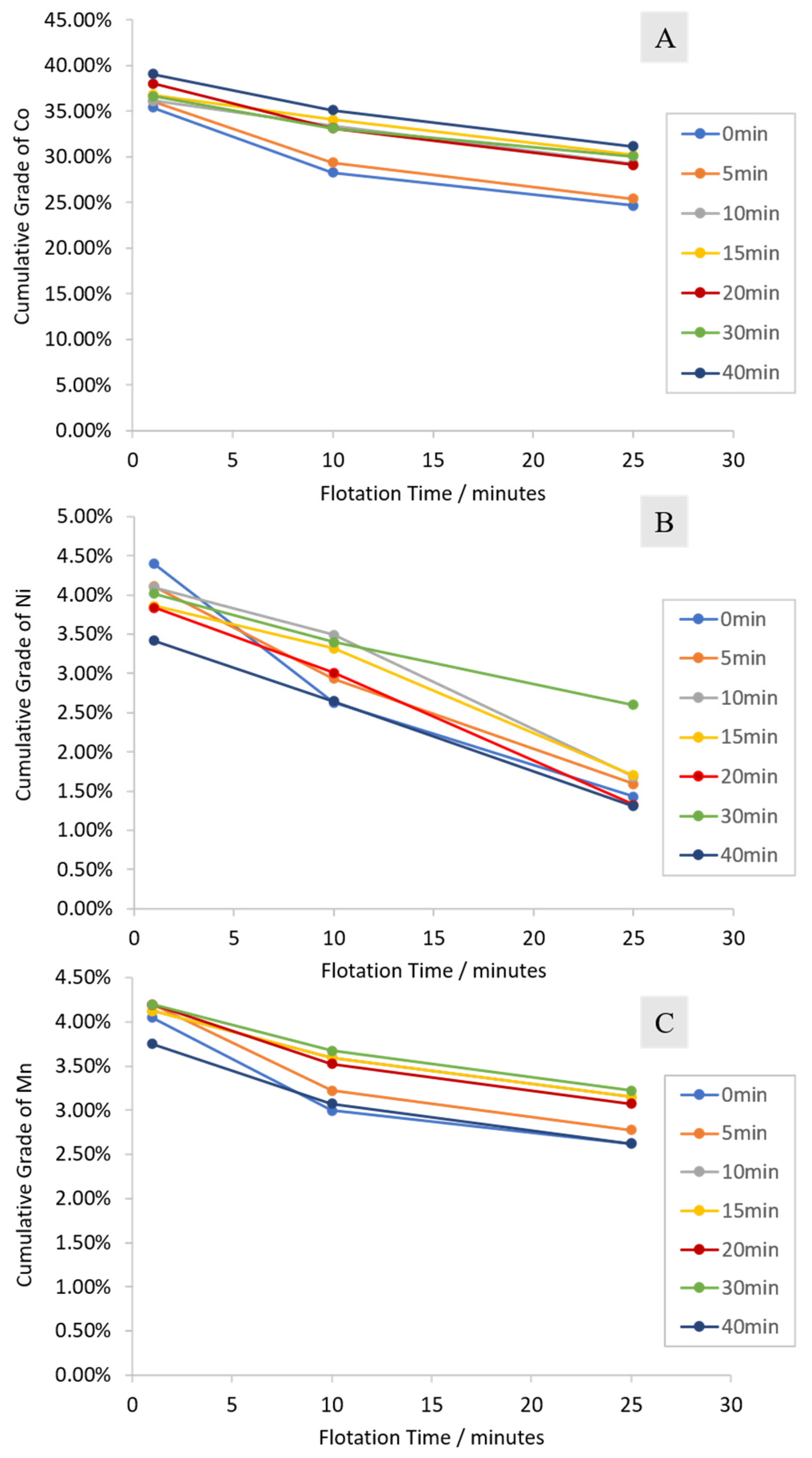
3.2.1. Cumulative Grades and Recoveries

The froth flotation results for the metallic components of waste LIBs after various activation times are compiled in Figure 6, Figure 7 and Figure 8.
As Figure 6, Figure 7 and Figure 8 show, when the binder surfaces are not removed, cathode active material recoveries of ~70–80% can be achieved, while maintaining low (~10%) recovery of Cu. Low energy milling seems to improve the separation up to the 20-min mark, after which the separation efficiency stabilizes. In this experimental series, the optimal separation was achieved using 20-min milling time, with cumulative recoveries (after 25 min) of 81.3%, 67.6%, and 78.4%, for Co, Ni, and Mn, respectively. The cumulative recovery for Cu in the overflow was only 10% (i.e., 90% recovery in the tailings). Furthermore, the separation efficiency of Cu, with the optimal 20-min milling time, was reported to be −54.5%, indicating an efficient enrichment to the underflow. It is to be noted that even though only 7.4 wt% of Cu was floated with 5-min milling time (92.6% recovery in tailings, Figure 8A), the enhanced separation of the active materials using longer milling times ultimately results in an increased Cu separation efficiency. Milling enhances the Cu separation efficiency noticeably, as the SE value for Cu in the absence of milling was −40.3%.
The results hereby presented indicate that flotation can be applied for the selective recovery of the leftover black mass in the Cu-Al rich sieve overflow, by extracting the active particles in the froth phase and simultaneously enriching Al and Cu in the tailings. The Al-Cu enriched tailings are a valuable material stream on its own, and it could be further separated relatively easily via density-based separation, for example.
The exact mechanism of the extraction of the cathode active components in a seemingly true flotation manner is unknown. A reasonable explanation is that the floatability of the cathode materials is a result of the PVDF binder coating, which arguably hydrophobizes the Li-salt particles. The observed trend of improved floatability with respect to grinding time could also be a result of the different grinding response of graphite and the anode materials, as graphite is softer than the crystal structures of the cathode. Yu et al. [25] described the floatability of ground black mass, and reported that short grinding times (<5 min) resulted in an increment in the floatability of the cathode active components. This was hypothesized to be a result of anode-cathode aggregate formation. In the aforementioned article, the purpose of the milling was to wear down the binder surfaces, and it is likely that a higher energy mill was used compared to the one applied in this article. Consequently, it is plausible that the increased floatability of the cathode components reported in this article after longer grinding times (20 min and above) could also be a result of the anode–cathode aggregate formation. Furthermore, when milled with a low energy input, the adhered black mass particles are expected to be liberated from the Cu, Al, and plastic surfaces, allowing for a larger amount of the active particles to be extracted via true flotation. Nevertheless, as Figure 6 shows, grinding is not necessary for the floatability of the cathode, as significant Co, Ni, and Mn recoveries (~60%) were reported in this study, even in the absence of milling (0 min milling time).
The recovery of Cu and the other macroscopic components (Al, plastic separator) in the froth fractions, however, is likely a result of the hydrodynamic conditions in the flotation cell, and the density of these materials. The plastic films, for example, are so lightweight that they float readily on top of the suspension surface even before the airflow was started. Cu and Al, on the other hand, tend to sink at first, but the strong agitation in the flotation cell continuously carries a certain amount of these particles towards the froth fraction. This behavior is more akin to entrainment than true flotation and could be tested in future works by changing the parameters that effect the hydrodynamic conditions of the flotation process, such as the agitation speed, and the volume/geometry of the flotation cell.

3.2.2. Characterization of the Froth Fraction Used for the Nickel Slag Cleaning

The 0–1 min froth fraction was selected for further pyrometallurgical treatment, due to its observed highest graphite content. The average cumulative grade of the combined 0–1 min froth fractions (two experiments with 20 min milling) are presented in Table 2, along with the average head grade of the two experiments. The amounts of oxygen and lithium in Table 2 were calculated based on the assumption that O and Li are present with a relative molar ratio of 2:1 and 1:1 with respect to Co, respectively, according to commercial Co-containing cathode chemistries. In the 0–1 min fraction, the other materials are expected to be predominantly graphite, Al, F, P, and Fe. In the calculated head grade, the other materials are expected to be primarily Al, graphite, and the separator film plastics.
Characterizing the froth fraction quantitatively for graphite is difficult due to the heterogeneous composition of the industrial LIB waste. One main complication is that, in addition to the graphite anode, other sources of carbon are present in the material, namely carbon black, PVDF, and separator films. To achieve an accurate characterization with Fourier-transform infrared spectroscopy, for example, these carbon sources need to be thoroughly removed, possibly via roasting/acid leaching pretreatment. Other traditional carbon characterization techniques such as Raman spectroscopy are vulnerable to the fluorescent response of the metallic Al and Cu particles that are present in the froth fraction. Likewise, the multiple cathode chemistries, and different elemental ratios within similar cathode chemistries, hinder the applicability of X-ray diffraction for quantitative characterization. Therefore, and considering that the aim of the present manuscript is to evaluate the use of flotation products as smelter feed rather than their separation into high purity components, the graphite concentration hereby presented is an estimate based on the concentrations of the other components that can be accurately measured.
To estimate the amount of graphite in the 0–1 min fraction, the following series of assumptions are made. Firstly, Al is expected to be present in a similar or slightly higher concentration than Cu, as its lower density makes it more likely for the Al particles to end up in the froth fraction. Furthermore, as indicated by Figure 4 and Figure 5, Al-containing cathode chemistries are expected to be present in the feed, likely increasing the Al content of the froth fraction. Secondly, F is expected to be present in a similar concentration range as Li. Thirdly, taking into account the possible LFP cathode content (indicated by Figure 4 and Figure 5), the concentration of Fe, P, and other elements is expected to be in the range of 1.5–2 wt%. This results in a conservative estimate of 19–20 wt% for the graphite grade in the 0–1 min fraction.
As Table 2 shows, in the 0–1 min fraction, the grades of the elements associated with the cathode active components (Co, Ni, Mn, O, Li) were nearly doubled when compared to the head grade, and a drastic reduction in the Cu grade was reported (from 24.29 wt% to 1.95 wt%). This suggests that, during the first minute of the flotation process, a very selective separation of the active material takes place. These high grades were associated with recovery values ranging from 34% (Ni) to 38% (Co and Mn), as indicated by Figure 6. Even though the separation efficiency was improved towards the later stages of the experiment (Figure 6 and Figure 8B), the chemical composition and especially the assumed high graphite grade made the 0–1 min fraction particularly attractive for the pyrometallurgical slag cleaning procedure. It is noteworthy, that even though the head grade of “others” was higher compared to the assumed graphite grade in the 0–1 min fraction, graphite could still be expected to be enriched to the froth. This is because the Al grade was expected to drop in the froth fraction, following a similar trend to Cu.
Elemental mapping at the microstructure of 0–1 min froth fraction by scanning electron microscopy (SEM) with energy dispersive X-ray spectrometry (EDS) is presented in Figure 9. The results confirmed the assumptions described above. It can be seen that the cobalt, nickel, and manganese were concentrated together in the grains of cathode material, whereas aluminum was present separately in the form of wires. Carbon presence between the grains of cathode material was detected.

3.3. Reduction of Metals

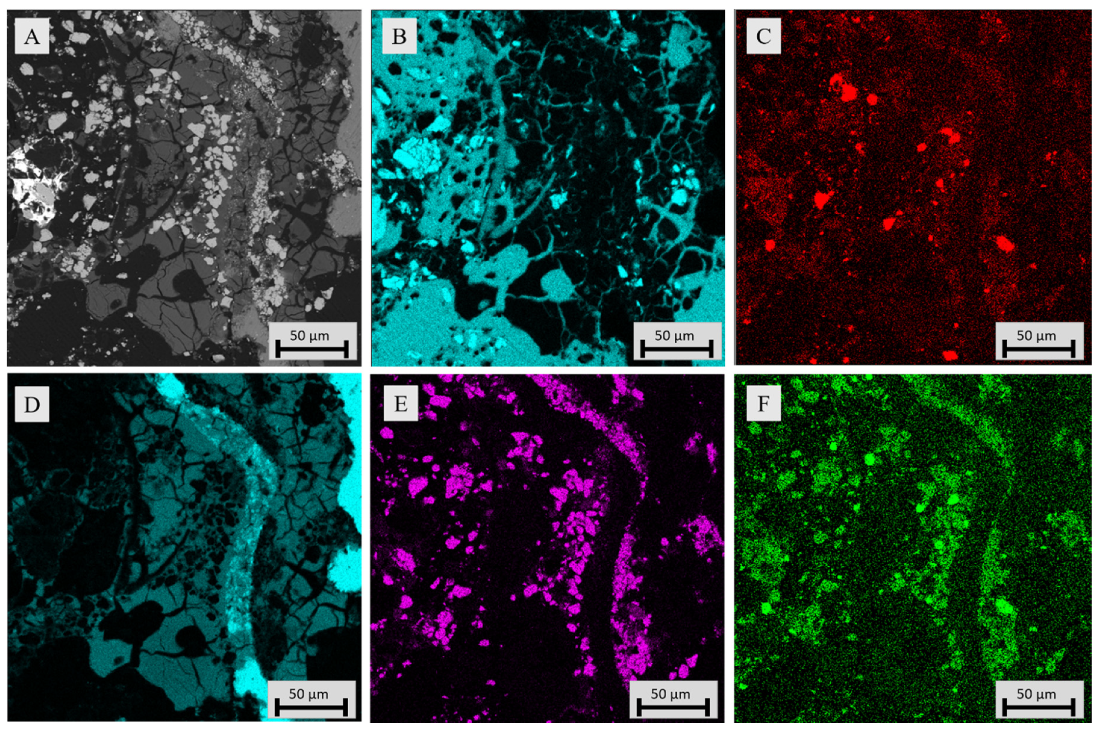
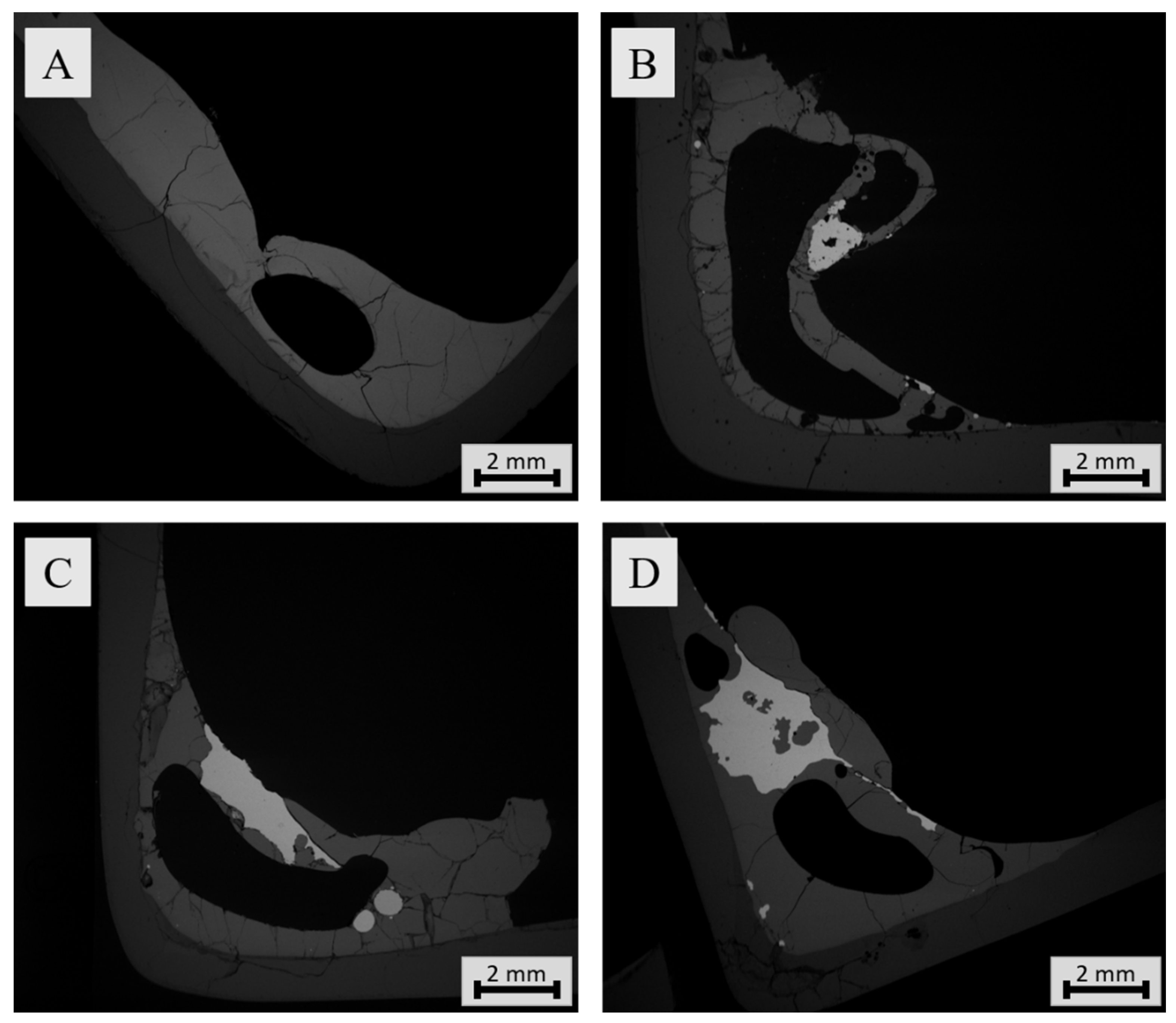
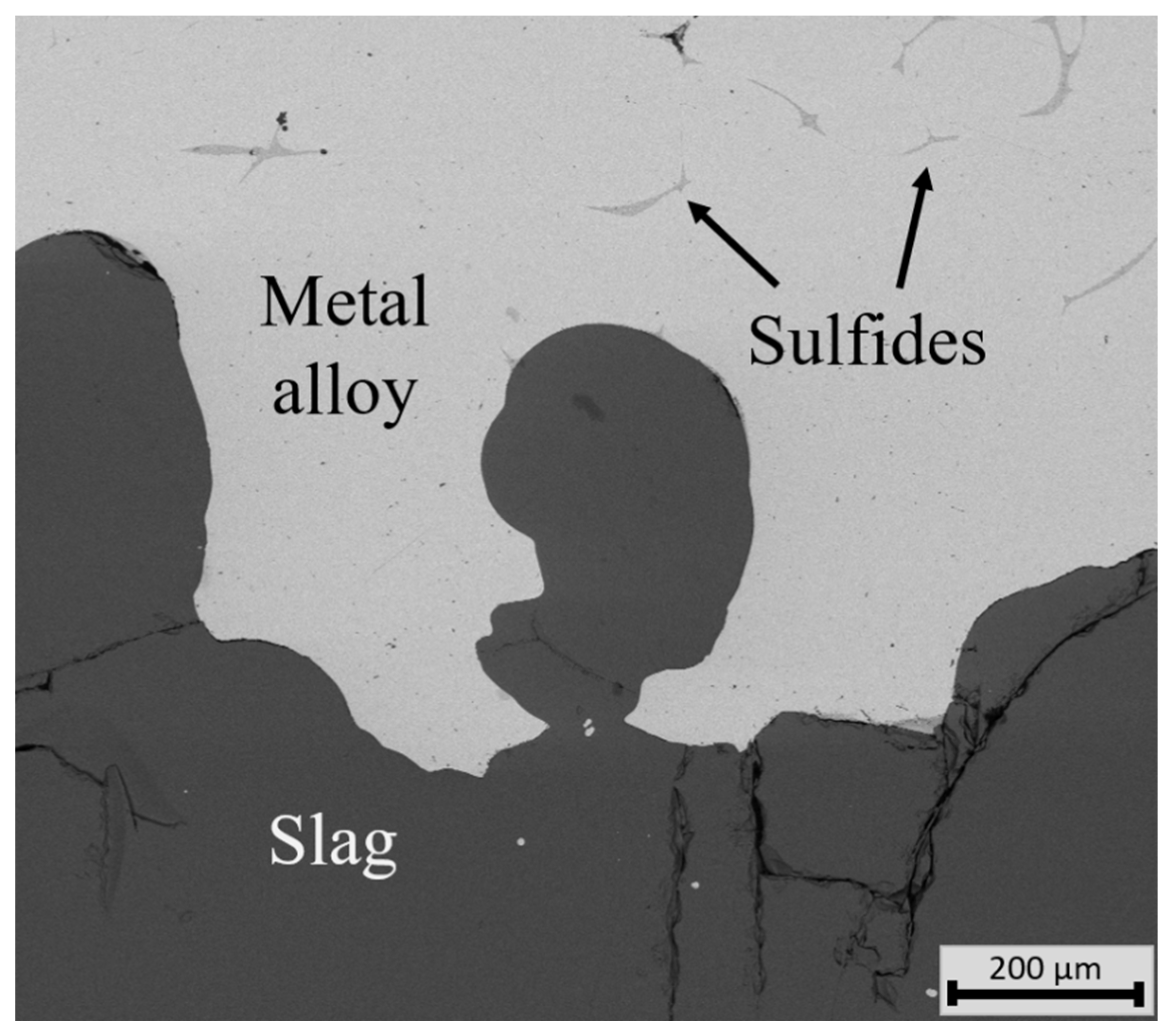
3.3.1. Sample Microstructure

Figure 10 shows SEM-backscattered electron (BSE) micrographs of different samples. Figure 10A shows the microstructure of molten slag without any additions after 20 min contact time in argon atmosphere, whereas Figure 10B–D show the microstructures of samples with slag-battery scrap system for 5, 30, and 60 min contact times, respectively. The visual observations did not indicate much difference between the sample structures after different contact times. Even after 5 min contact time, the metal alloy (the lightest color in the micrograph) had already formed in the sample, as is seen in Figure 10B. This was expected based on earlier findings by Ruismäki et al. [24].
The typical microstructure of a sample with slag-battery scrap system consisted of a glassy slag and metal alloy, presented in Figure 11. The metal alloy was mainly homogenous, but contained some sulfides (matte), which are also visible in the micrographs and seemed to concentrate on grain boundaries. In most samples, the metal alloy was concentrated into metal droplet and was located on top of the slag. The metal alloy had not yet settled to the bottom of the crucible as opposed to industrial nickel slag cleaning process. The chemical composition of the slag and metal are presented in Section 3.3.2 and Section 3.3.3, respectively.

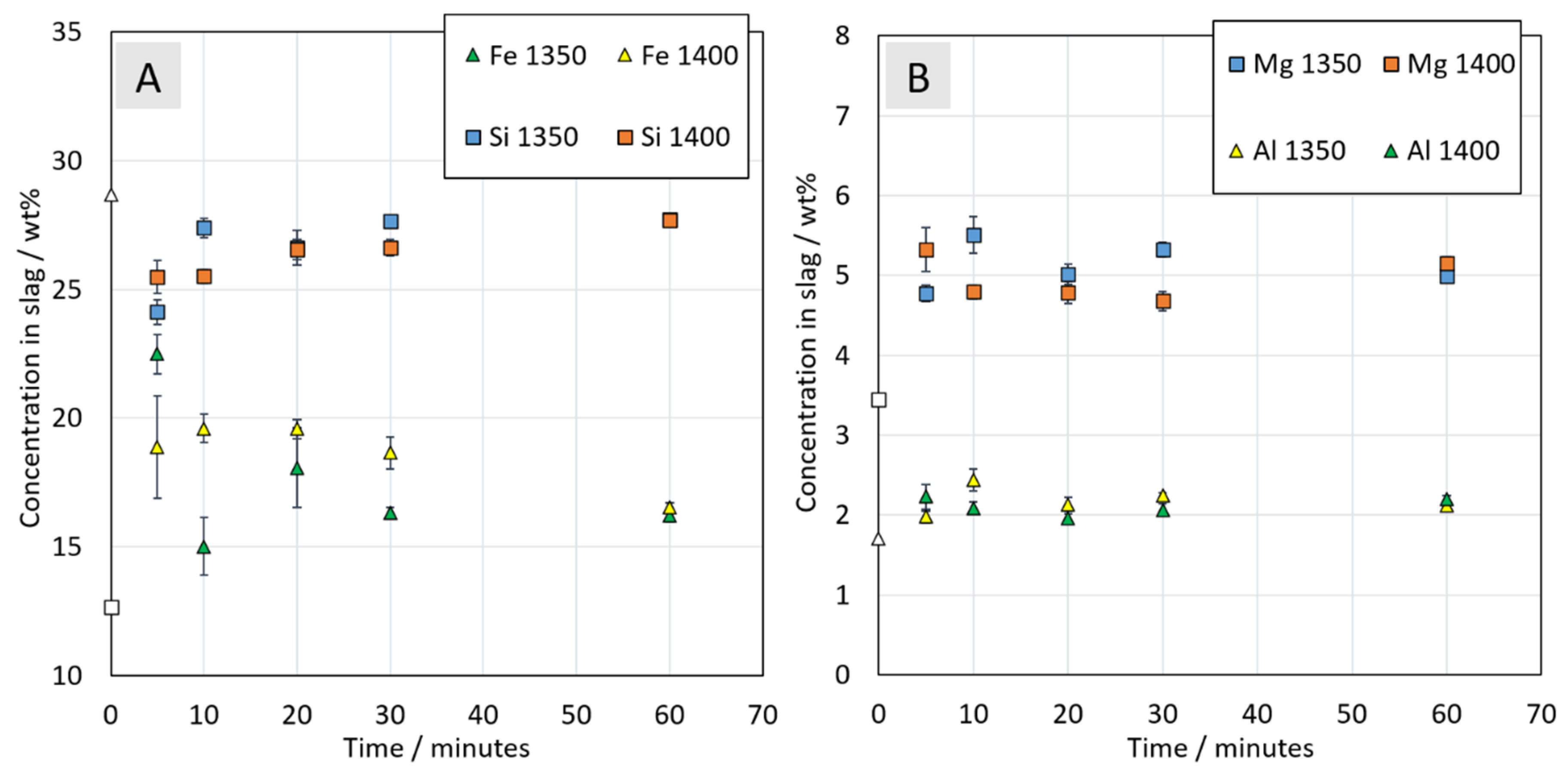
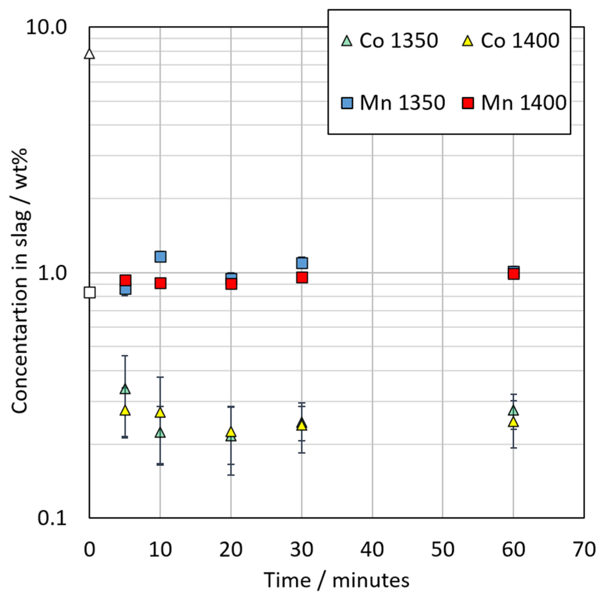
3.3.2. Chemical Composition of Slag

The starting slag mixture, used in the simulated conditions of an electric arc furnace, consisted of 80 wt% of industrial nickel-slag and 20 wt% battery fraction from 0–1 min flotation time. The chemical composition of the prepared mixture, seen in the Table 3, was calculated based on chemical composition of the nickel-slag (Table 1) and the 0–1 min froth fraction (Table 2). The composition of starting mixture was selected based on a previous study by Ruismäki et al. [24]. In this study, it was indicated that the addition of battery scrap rich in cobalt has an increasing effect of cobalt recovery in nickel slag cleaning.
Figure 12 presents the concentrations of major elements: Fe, Si, Mg, and Al in the slag as a function of contact time in argon atmosphere. It was observed that the most significant change in concentrations of major elements occurred in the first 5 min. The concentrations of elements do not seem to vary between 1350 °C and 1400 °C.
After 5-min contact time, the concentration of Fe in the molten slag decreased significantly in comparison to its concentration in the starting mixture (Table 3). Iron concentration in the slag increased slightly as the contact time increased.
The concentrations of Si, Mg, and Al in the slag were significantly higher already after 5 min in comparison to their concentrations in the starting mixture. Si concentration in slag increased with the increasing contact time and reached the concentration of 27.7 wt% after 60 min contact time, which corresponds to 59.3 wt% of SiO2. The increase in silica concentration in the slag was connected with dissolution of silica crucible used in the experiments and reduction of metal oxides to the metal alloy.
The concentrations of Mg and Al in the slag remained stable between 5 and 60 min, about 5 wt% and 2 wt%, respectively, corresponding to 8.3 wt% of MgO and 3.8 wt% of Al2O3.
Figure 13 shows concentrations of cobalt and manganese in the metal alloy. Nickel and copper concentrations in the slag were under detection limit of the EDS. Extremely low concentrations (under detection limit) of nickel and copper in the slag phase suggest that their oxides were successfully reduced to metallic form.
Manganese concentration in the slag varies slightly between 0.9 and 1.2 wt%. As was presented in a previous study [21], manganese oxide is characterized by a high thermodynamic stability at high temperatures and is therefore sometimes used as a deoxidizing agent. The feasibility of recovering manganese from slags should be researched in case an increasing amount of manganese ends up in slags. The precipitation of nanomanganese ferrite from industrial metallurgical slags by the oxidation route has been proposed [34].
Cobalt concentration in the slag decreased significantly in comparison to its concentration in the starting mixture (7.8 wt%). After 5-min contact time, its concentration in slag was about 0.2 wt% and seemed to be stabilized between 10 and 60 min contact time. This information suggests that a significant portion (about 93%) of cobalt was reduced to metal alloy. Similarly, as for the major elements, the concentrations of the minor elements do not seem to vary between experiments conducted at 1350 °C and 1400 °C.

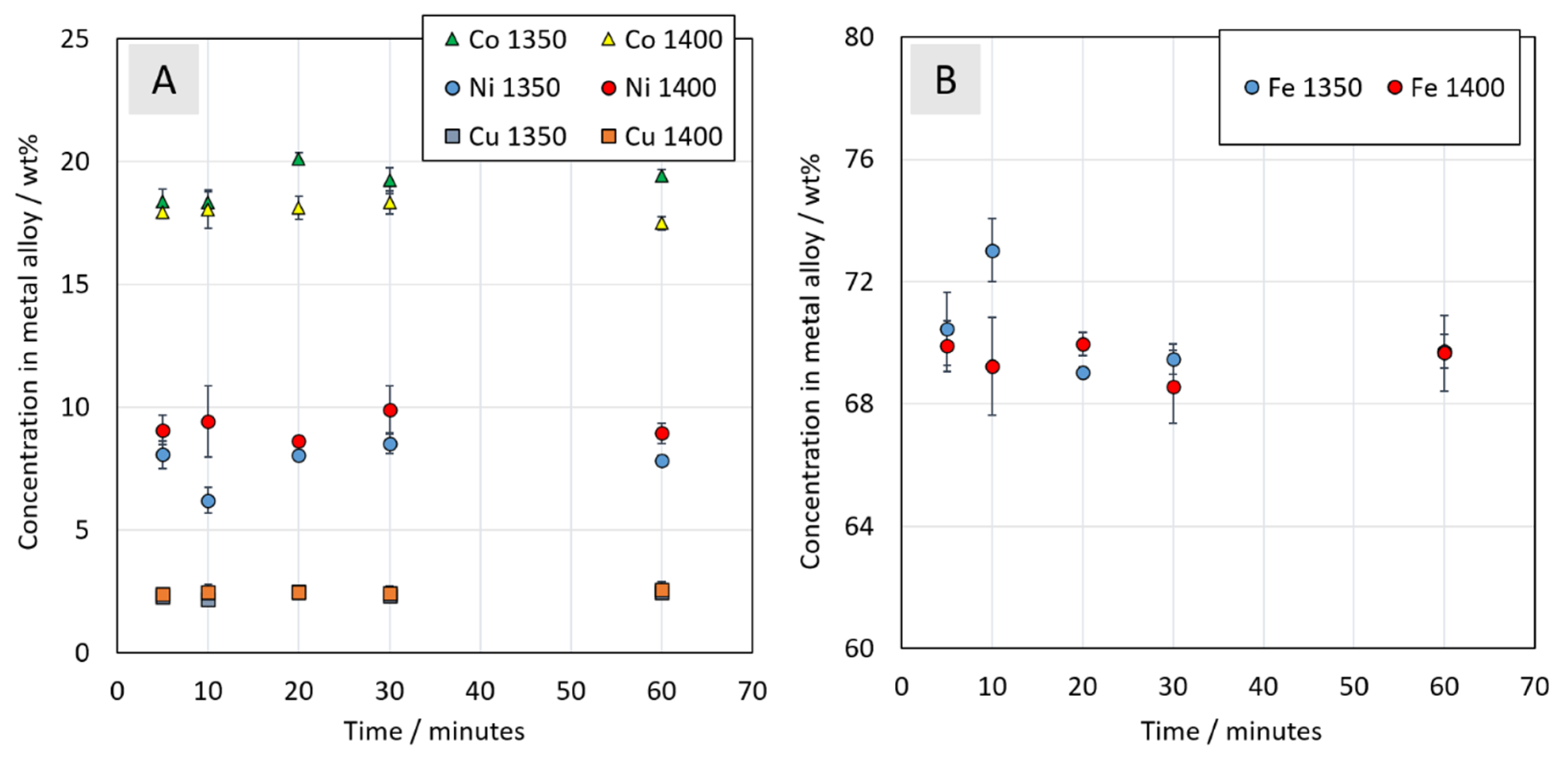
3.3.3. Chemical Composition of Metal Alloy

A Co-Ni-Fe-Cu metal alloy was formed in all samples, even after the shortest contact time of 5 min. The elemental composition of the metal alloy is shown in Figure 14. Concentrations of cobalt, nickel, copper, and iron did not seem to change between 5 and 60 min contact times or at different temperatures. The formed alloy consisted of about 2.5 wt% of copper, 9 wt% of nickel, 18 wt% of cobalt, and 70 wt% of iron. Based on the results, the reduction of metal oxides by using graphite as a reductant is possible and the kinetics are extremely fast.
The reason for the fast reduction of metal oxides might be caused by the relatively small particle size of the graphite and the metal fraction increasing its density. Additionally, the flotation fraction containing graphite was evenly mixed with the nickel-slag making the reductant readily available for the metal oxides within short diffusion distances. Compared to conventional slag cleaning, the coke floats on top of the slag resulting in the top layer of the slag to be reduced first. Instead, in this approach, the reduction proceeds supposedly quite evenly in the molten slag-battery scrap mixture. Furthermore, an even reduction behavior enables the coalescence of forming metal droplets into larger droplets relatively quickly. Thus, further analysis on the optimum charging procedure e.g., whether the reductant should be charged as mixed, on the bottom or on the top of the slag or even injected should be conducted.

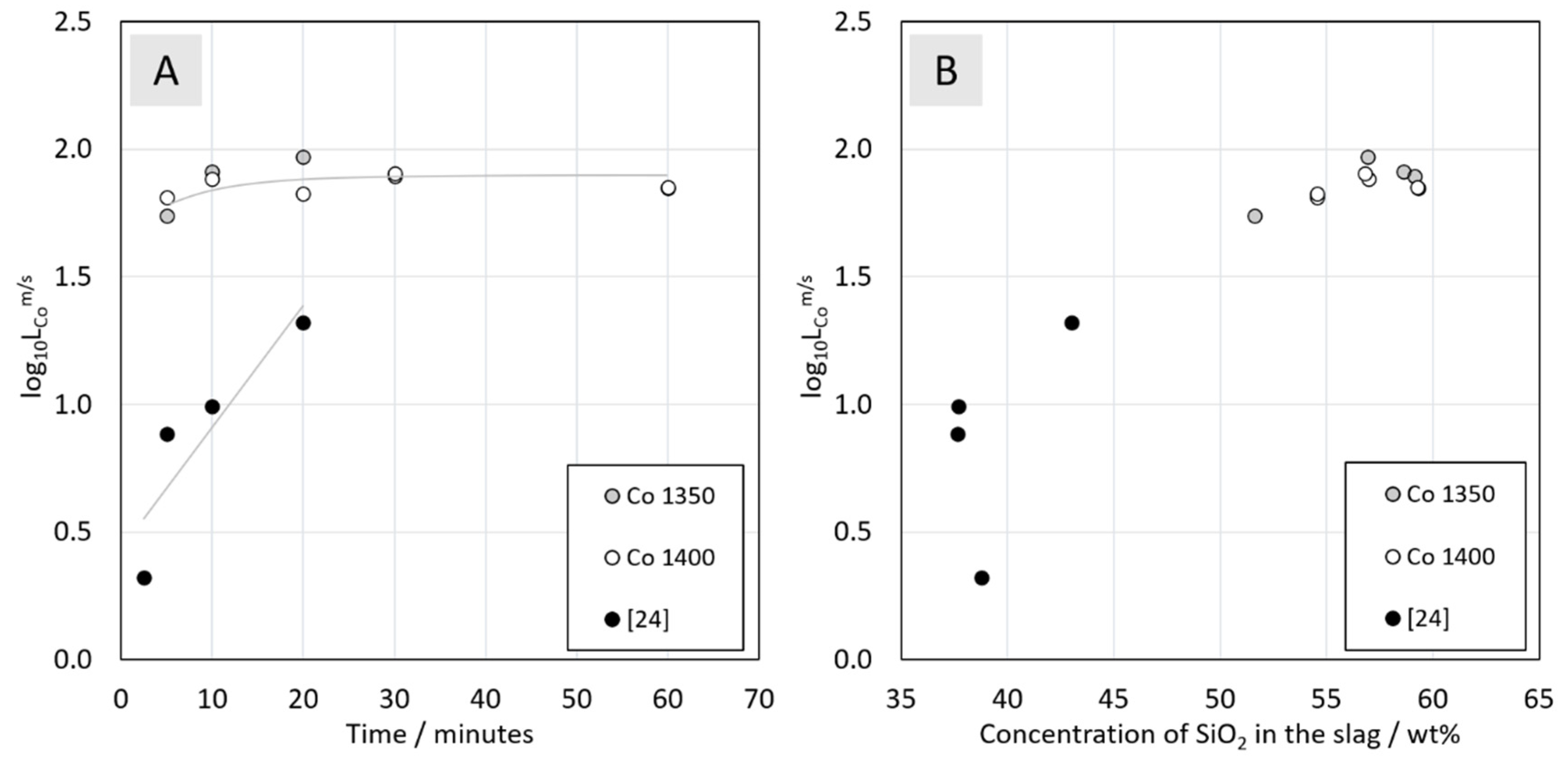
3.3.4. Distribution of Cobalt between Metal Alloy and the Slag

In a system with two phases, the distribution equilibrium of elements between e.g., a slag (s) and a metal or metal sulfide phase (m) can be described with distribution coefficients. The distribution coefficient of an element Me between two phases is expressed as the ratio of weight concentrations of Me dissolved in these phases in equilibrium [35].
Figure 15 presents the distribution coefficient of cobalt between metal alloy and the slag. The temperatures of 1350 and 1400 °C do not have an impact on the cobalt distribution coefficient. This is in agreement with the results of Piskunen et al. [36], which showed that temperature range between 1350 °C and 1450 °C had relatively small effect on the matte-slag distribution coefficients. The results indicate that the distribution coefficient of cobalt reached its maximum during the first 5–10 min. The mass distribution should be studied in order to see whether maximum recovery was reached or not. Previous studies in similar conditions (5 wt.% of Co in the starting mixture, added as synthetic oxide) reported distributions coefficients of cobalt between metal and slag of 101.0 after 10-min reduction time and approximately 101.4 after 20 min [24]. In the present study, the reaction rate was higher by the reduction with graphite, as the coefficient was about 101.9 after 10 min and stabilizes as opposed to the previous studies. The high concentration of cobalt in the starting mixture seems to result in a higher distribution coefficient, and the end concentration of cobalt in the slag was lower compared to the previous studies [24]. Therefore, it is suggested that the reduction kinetics within the first five minutes should be researched in more detail.
Figure 15B shows the distribution coefficient of cobalt between metal alloy and the slag as a function of silica concentration in the slag. It was observed that the increasing silica concentration in the slag has an increasing effect on cobalt distribution coefficient. This information is in agreement with the study of Hellstén et al. [37] on slag cleaning equilibria in iron silicate slag-copper system. According to their observations, Fe/SiO2 ratio has a significant effect on trace elements distribution between metal alloy and the slag. Hellstén et al. concluded that reduction of metal oxides can be optimized by adjusting SiO2 concentration in slag and the goal should be to maintain the slag compositions higher than about 28 wt% [37]. The previous study of Ruismäki et al. together with the present study confirmed these findings, even though the silica concentration in the slag in this study was much higher, 35–43 wt% [24] versus 51–59 wt%, respectively.
However, at high silica concentrations, the viscosity of the slag increases, resulting in the decreasing reaction rates and the settling rate of particles through the slag layer [37,38]. As seen in Figure 10, the metal alloy is collected on top of the slag even after longer reduction times, as opposed to industrial practices, implying that the silica concentration may be too high for settling. The addition of basic fluxing agents (e.g., CaO, MgO) releases strong silicate formers as trace elements from the slag and increases the viscosity [37,38]. The solubility of weak silicate formers e.g., NiO, FeO and CoO in the slag, on the other hand, decreases with increasing SiO2 concentration [37]. A high viscosity could also slow down the reduction rate by entraining the remaining oxides of the valuable metals in the slag as the concentration of the metals in the slag or metal alloy did not change significantly after 10 min. This is supported by the increase of the silica concentration after 10 min. Experiments with longer reduction times would give additional information on the equilibrium concentrations of the elements.
In order to separate the valuable metals, such as Co, Ni, and Cu, further refinement by pyrometallurgical or hydrometallurgical processes is essential. The concentration of the metals in the product, i.e., the metal alloy, should the adjusted partially according to the limitations of the subsequent processes. The reductant to metal oxide ratio and reduction time play major roles in adjusting the final concentrations of the metal alloy product. In many cases, Fe is considered as a non-valuable metal or impurity, whereas Co, Ni, and Cu are recovered selectively [39]. If the subsequent processing requires lower iron concentration in the metal alloy, iron can be selectively oxidized from the metal alloy by using air or oxygen and adding silica flux enables the formation of a fayalitic slag [40]. Optionally, the metal alloy from slag cleaning can be granulated and leached in order to separate Fe, Co, Cu, and Ni in a controlled way similarly as in the direct Outotec nickel flash smelting process [40]. Benefits of lower iron concentration in the metal alloy include lower processing costs of hydrometallurgical separation [41]. For maximizing resource efficiency, the recovery of metals from pyrometallurgical slags and finding greener options for replacing landfilling of slags has gained an increasing attention lately [11]. For instance, sodium roasting and subsequent water leaching has been proposed by Li et al. [42] for recovering lithium from pyrometallurgical slag, while the recovery of manganese from slags has been studied by Ayala and Fernández [43] and Baumgartner and Groot [44].
As the Co, Ni, Cu, and Fe oxides are seemingly easily and rapidly reduced with the presented parameters, reducing the amount and accessibility of the reductant, i.e., changing the charging procedure of the reductant could slow down the reaction rate and allow to adjust the final concentration. Therefore, optimizing the product concentration while keeping in mind further refinement possibilities is of industrial importance.

4. Conclusions

According to the results, the integration of industrial nickel slag cleaning and LIB recycling was successful. This study presents a novel multifold approach in which:
  • Froth flotation is introduced as a mechanical pre-treatment for pyrometallurgical battery recycling
  • Graphite in the flotation fraction is utilized to replace coke in the nickel slag cleaning.
The laboratory-scale flotation experiments show that when the black mass is not pretreated for the PVDF binder removal, both the anode and the cathode display a hydrophobic response and can be recovered in the froth phase. This allows the recovery of the left-over black mass from the Cu-Al rich sieve overflow in a purity comparable to the underflow of the sieve, thus increasing the overall black mass recovery of the initial mechanical processing. Low-energy milling was demonstrated to improve the black mass separation, and the optimal separation efficiency was achieved with 20-min milling time.
A proof-of-concept for the processing of industrial nickel slag using solely graphite obtained from the flotation of LIB waste as a reductant was reported for the first time. When the 0–1 min flotation fraction was mixed with industrial nickel slag in a 1:4 ratio, the metals deportment into the matte/alloy phase started immediately when the mixture reached the process temperature. The results indicated that the distribution coefficient of valuable metals reached maximum within 5 min reduction time.
The reason for a fast reduction of metals might be caused by the relatively small particle size of graphite and its even distribution in the mixture prior to melting. In conventional nickel slag cleaning, the coke is charged on top of the slag as the coke is lighter than the slag, resulting in the top parts of the slag to be reduced first. In practice, various measures are taken for improving phase contact and slag mixing in the electric furnace in order to enhance reduction of ferric oxide to ferrous after which the valuable metals can start to reduce. Instead, in this approach, the reduction appears to proceed quite evenly in the molten slag. Thus, further analysis on the optimum charging procedure e.g., whether the reductant should be charged mixed, on the bottom or on the top of the slag should be conducted. It should be noted, that in industrial slag cleaning, the slag is tapped molten from the nickel smelting furnace and in this approach, it was not the case.
For optimizing the process parameters further, the ratio of Ni-slag and battery scrap is of importance as the reductant concentration has a great impact on the forming metal alloy and its metal concentration. Therefore, mixing varying flotation fractions with the nickel slag should be studied further. Additionally, the elemental concentrations in the metal alloy should be optimized keeping in mind the further refining steps. This study suggests preliminarily that any excess carbon available after the reduction of Co, Ni, and Cu will increase the concentration of iron in the metal alloy. Due to thermodynamic constraints, it is not possible to avoid the co-reduction of iron when recovering valuable metals. However, for further refining requirements, the possibility of decreasing Fe concentration in metal alloy should be investigated. A thorough comparison with graphite and other reductants, such as coke, biochar, and methane, used in nickel slag cleaning should be conducted as well.

Author Contributions

Conceptualization, A.J. and R.S.-G.; methodology, R.R., T.R., A.D., P.T., A.J., and R.S.-G.; software, R.R., T.R., and A.D.; validation, R.R., T.R., A.D., A.J., and R.S.-G.; formal analysis, R.R., T.R., and A.D.; investigation, R.R., T.R., and A.D.; resources, A.J. and R.S.-G.; data curation, R.R., T.R., and A.D.; writing—original draft preparation, R.R., T.R., and A.D.; writing—review and editing, P.T., A.J., and R.S.-G.; visualization, R.R., T.R., and A.D.; supervision, A.J. and R.S.-G.; project administration, A.J. and R.S.-G.; funding acquisition, A.J. and R.S.-G. All authors have read and agreed to the published version of the manuscript.

Funding

This research was funded by BATCircle project, grant number 4853/31/2018, SYMMET project, grant number 3891/31/2018, and ReVolt project, grant number 08_2018_IP167_ReVolt.

Acknowledgments

The authors are grateful to Boliden Harjavalta (Finland) for providing industrial nickel slag and Akkuser Oy (Finland) for providing battery scrap. The authors are grateful for Lassi Klemettinen for his SEM-EDS expertise and proofreading the article. This study utilized the RawMatTERS Finland infrastructure (RAMI, Academy of Finland) in Aalto University, VTT Espoo and GTK Espoo. The authors would like to express their gratitude to the Helmholtz Institute Freiberg for Resource Technology, for allowing the use of their research infrastructure, and Anna Vanderbruggen for her expertise in the waste battery characterization. Tommi Rinne is grateful for the doctoral study grant provided by the Finnish Steel and Metal Producers’ Fund.

Conflicts of Interest

The authors declare no conflict of interest.

References

  1. Huang, B.; Pan, Z.; Su, X.; An, L. Recycling of lithium-ion batteries: Recent advances and perspectives. J. Power Sources 2018, 399, 274–286. [Google Scholar] [CrossRef]
  2. A Vision for a Sustainable Battery Value Chain in 2030, Insight Report, September 2019. Unlocking the Full Potential to Power Sustainable Development and Climate Change Mitigation. Available online: http://www3.weforum.org/docs/WEF_A_Vision_for_a_Sustainable_Battery_Value_Chain_in_2030_Report.pdf (accessed on 4 March 2020).
  3. Wentker, M.; Greenwood, M.; Leker, J. A bottom-up approach to lithium-ion battery cost modeling with a focus on cathode active materials. Energies 2019, 12, 504. [Google Scholar] [CrossRef] [Green Version]
  4. Commission Staff Working Document on the Evaluation of the Directive 2006/66/EC on Batteries and Accumulators and Waste Batteries and Accumulatros and Repealing Directive 91/157/EEC. Available online: https://ec.europa.eu/environment/waste/batteries/pdf/evaluation_report_batteries_directive.pdf (accessed on 23 April 2020).
  5. Shi, J.; Chen, M.; Li, Y.; Eric, H.; Klemettinen, L.; Lundström, M.; Taskinen, P.; Jokilaakso, A. Sulfation roasting mechanism for spent lithium-ion battery metal oxides under SO2-O2-Ar atmosphere. JOM 2019, 71, 4473–4482. [Google Scholar] [CrossRef] [Green Version]
  6. Wang, X.; Gaustad, G.; Babbitt, C.W.; Richa, K. Economies of scale for future lithium-ion battery recycling infrastructure. Resour. Conserv. Recycl. 2014, 83, 53–62. [Google Scholar] [CrossRef]
  7. Bernhart, W. Recycling of lithium-ion batteries in the context of technology and price developments. Atzelectron. Worldw. 2019, 14, 38–43. [Google Scholar] [CrossRef]
  8. Gu, F.; Guo, J.; Yao, X.; Summers, P.A.; Widijatmoko, S.D.; Hall, P. An investigation of the current status of recycling spent lithium-ion batteries from consumer electronics in China. J. Clean. Prod. 2017, 161, 765–780. [Google Scholar] [CrossRef]
  9. Werner, D.; Peuker, U.A.; Mütze, T. Recycling chain for spent lithium-ion batteries. Metals 2020, 10, 316. [Google Scholar] [CrossRef] [Green Version]
  10. Zheng, X.; Zhu, Z.; Lin, X.; Zhang, Y.; He, y.; Cao, H.; Sun, Z. A mini-review on metal recycling from spent lithium ion batteries. Engineering 2018, 4, 361–370. [Google Scholar] [CrossRef]
  11. Rämä, M.; Nurmi, S.; Jokilaakso, A.; Klemettinen, L.; Taskinen, P.; Salminen, J. Thermal processing of jarosite leach residue for a safe disposable slag and valuable metals recovery. Metals 2018, 8, 744. [Google Scholar] [CrossRef] [Green Version]
  12. Directive 2006/66/EC of the European Parliament and of the Council of 6 September 2006 on Batteries and Accumulators and Waste Batteries and Accumulators and Repealing Directive 91/157/EEC. Available online: https://eur-lex.europa.eu/legal-content/EN/TXT/PDF/?uri=CELEX:02006L0066-20131230&rid=1 (accessed on 30 March 2020).
  13. Harper, G.; Sommerville, R.; Kendrick, E.; Driscoll, L.; Slater, P.; Stolkin, R.; Walton, A.; Christensen, P.; Heidrich, O.; Lambert, S.; et al. Recycling lithium-ion batteries from electric vehicles. Nature 2019, 575, 75–86. [Google Scholar] [CrossRef] [Green Version]
  14. Velázquez-Martínez, O.; Valio, J.; Santasalo-Aarnio, A.; Reuter, M.; Serna-Guerrero, R. A critical review of lithium-ion battery recycling processes from a circular economy perspective. Batteries 2019, 5, 68. [Google Scholar] [CrossRef] [Green Version]
  15. Nitta, N.; Wu, F.; Lee, J.T.; Yushin, G. Li-ion battery materials: Present and future. Mater. Today 2015, 18, 252–264. [Google Scholar] [CrossRef]
  16. Lv, W.; Wang, Z.; Cao, H.; Sun, Y.; Zhang, Y.; Sun, Z. A critical review and analysis on the recycling of spent lithium-ion batteries. ACS Sustain. Chem. Eng. 2018, 6, 1504–1521. [Google Scholar]
  17. Or, T.; Gourley, S.W.D.; Kaliyappan, K.; Yu, A.; Chen, Z. Recycling of mixed cathode lithium-ion batteries for electric vehicles: Current status and future outlook. Carbon Energy 2020, 2, 6–43. [Google Scholar] [CrossRef] [Green Version]
  18. Porvali, A.; Aaltonen, M.; Ojanen, S.; Velazquez-Martinez, O.; Eronen, E.; Liu, F.; Wilson, B.P.; Serna-Guerrero, R.; Lundström, M. Mechanical and hydrometallurgical processes in HCl media for the recycling of valuable metals from Li-ion battery waste. Resour. Conserv. Recycl. 2019, 142, 257–266. [Google Scholar] [CrossRef]
  19. Mayyas, A.; Steward, D.; Mann, M. The case for recycling: Overview and challenges in the material supply chain for automotive li-ion batteries. SMT 2018, 19. [Google Scholar] [CrossRef]
  20. Chen, M.; Ma, X.; Chen, B.; Arsenault, R.; Karlson, P.; Simon, N.; Wang, Y. Recycling end-of-life electric vehicle lithium-ion batteries. Joule 2019, 3, 2622–2646. [Google Scholar] [CrossRef]
  21. Dańczak, A.; Klemettinen, L.; Kurhila, M.; Taskinen, P.; Lindberg, D.; Jokilaakso, A. Behavior of battery metals lithium, cobalt, manganese and lanthanum in black copper smelting. Batteries 2020, 6, 16. [Google Scholar] [CrossRef] [Green Version]
  22. Ren, G.; Xiao, S.; Xie, M.; Pan, B.; Chen, J.; Wang, F.; Xia, X. Recovery of valuable metals from spent lithium ion batteries by smelting reduction process based on FeO-SiO2-Al2O3 slag system. Trans. Nonferr. Metals Soc. 2017, 27, 450–456. [Google Scholar] [CrossRef]
  23. Ren, G.; Xiao, S.; Xie, M.; Pan, B.; Fan, Y.; Wang, F.; Xia, X. Recovery of valuable metals from spent lithium-ion batteries by smelting reduction process based on MnO-SiO2-Al2O3 slag system. In Advances in Molten Slags, Fluxes, and Salts, Proceedings of the 10th International Conference on Molten Slags, Fluxes and Salts (MOLTEN16), 22–25 May 2016; Reddy, R.G., Chaubal, P., Pistorius, P.C., Pal, U., Eds.; TMS (The Minerals, Metals & Materials Society): Pittsburgh, PA, USA, 2016. [Google Scholar]
  24. Ruismäki, R.; Dańczak, A.; Klemettinen, L.; Taskinen, P.; Lindberg, D.; Jokilaakso, A. Integrated battery scrap recycling and nickel slag cleaning with methane reduction. Minerals 2020, 10, 435. [Google Scholar] [CrossRef]
  25. Yu, J.; He, Y.; Ge, Z.; Li, H.; Xie, W.; Wang, S. A promising physical method for recovery of LiCoO2 and graphite from spent lithium-ion batteries: Grinding flotation. Sep. Purif. Technol. 2018, 190, 45–52. [Google Scholar] [CrossRef]
  26. Wang, F.; Zhang, T.; He, Y.; Zhao, Y.; Wang, S.; Zhang, G.W.; Zhang, Y.; Feng, Y. Recovery of valuable materials from spent lithium-ion batteries by mechanical separation and thermal treatment. J. Clean. Prod. 2018, 185, 646–652. [Google Scholar] [CrossRef]
  27. Liu, J.; Wang, H.; Hu, T.; Bai, X.; Wang, S.; Xie, W.; Juan, H.J.; He, Y. Recovery of LiCoO2 and graphite from spent lithium-ion batteries by cryogenic grinding and froth flotation. Miner. Eng. 2020, 148, 106223. [Google Scholar] [CrossRef]
  28. Zhang, G.; He, Y.; Feng, Y.; Wang, H.; Zhu, X. Pyrolysis-ultrasonic-assisted flotation technology for recovering graphite and LiCoO2 from spent lithium-ion batteries. ACS Sustain. Chem. Eng. 2018, 6, 10896–10904. [Google Scholar]
  29. Zhang, G.; He, J.; Wang, H.; Feng, Y.; Xie, W.; Zhu, X. Application of mechanical crushing combined with pyrolysis-enhanced flotation technology to recover graphite and LiCoO2 from spent lithium-ion batteries. J. Clean. Prod. 2019, 231, 1418–1427. [Google Scholar] [CrossRef]
  30. He, Y.; Zhang, T.; Wang, F.; Zhang, G.; Zhang, W.; Wang, J. Recovery of LiCoO2 and graphite from spent lithium-ion batteries by Fenton reagent-assisted flotation. J. Clean. Prod. 2017, 143, 319–325. [Google Scholar] [CrossRef]
  31. Wills, B.A.; Finch, J. Wills’ Mineral Processing Technology: An Introduction to the Practical Aspects of Ore Treatment and Mineral Recovery; Butterworth-Heinemann: Oxford, UK, 2015; ISBN 978-0-08-097053-0. [Google Scholar]
  32. Wan, X.; Jokilaakso, A.; Fellman, J.; Klemettinen, L.; Marjakoski, M. Behavior of Waste Printed Circuit Board (WPCB) materials in the copper matte smelting process. Metals 2018, 8, 887. [Google Scholar] [CrossRef] [Green Version]
  33. Wan, X.; Jokilaakso, A.; Iduozee, I.; Eric, H.; Latostenmaa, P. Experimental research on the behavior of WEEE scrap in flash smelting settler with copper concentrate and synthetic slag. In Proceedings of the EMC 2019, Düsseldorf, Germany, 23–26 June 2019; Volume 3, pp. 1137–1150. [Google Scholar]
  34. Semykina, A.; Seetharaman, S. Recovery of manganese ferrite in nanoform from the metallurgical slags. Metals Mater. Trans. B 2011, 42, 2–4. [Google Scholar] [CrossRef]
  35. Sukhomlinov, D.; Klemettinen, L.; Avarmaa, K.; O’Brien, H.; Taskinen, P.; Jokilaakso, A. Distribution of Ni, Co, precious and platinum group metals in copper making process. Metall. Mater. Trans. B 2019, 50, 1752–1765. [Google Scholar] [CrossRef] [Green Version]
  36. Piskunen, P.; Avarmaa, K.; O’Bren, H.; Klemettinen, L.; Johto, H.; Taskinen, P. Precious metal distributions in direct nickel matte smelting with low-Cu mattes. Metall. Mater. Trans. B 2017, 49, 98–112. [Google Scholar] [CrossRef]
  37. Hellstén, N.; Klemettinen, L.; Sukhomlinov, D.; O’Brien, H.; Taskinen, P.; Jokilaakso, A.; Salminen, J. Slag cleaning equilibria in iron silicate slag-copper systems. J. Sustain. Metall. 2019, 5, 463–473. [Google Scholar] [CrossRef] [Green Version]
  38. Shlesinger, M.E.; King, M.J.; Sole, K.C.T.G.; Davenport, W.G. Extractive Metallurgy of Copper—Chapter 5: Matte Smelting Fundamentals; Elsevier: Oxford, UK, 2011; pp. 73–88. [Google Scholar] [CrossRef]
  39. Stefanova, V.P.; Iliev, P.K.; Stefanov, B.S. Copper, nickel and cobalt extraction from FeCuNiCoMn alloy obtained after pyrometallurgical processing of deep sea nodules. In Proceedings of the Tenth ISOPE Ocean Mining and Gas Hydrates Symposium, Szczecin, Poland, 22–26 September 2013. [Google Scholar]
  40. Riekkola-Vanhanen, M. Finnish Expert Report on Best Available Techniques in Nickel Production; Finnish Environment Institute: Helsinki, Finland, 1999; ISBN 952-11-0507-0. Available online: https://helda.helsinki.fi/bitstream/handle/10138/40684/FE_317.pdf?sequence=1&isAllowed=y (accessed on 13 May 2020).
  41. Jones, R.T.; Denton, G.M.; Reynolds, Q.G.; Parker, J.A.L.; van Tonder, G.J.J. Recovery of cobalt, nickel, and copper from slags, using DC-arc furnace technology. In Proceedings of the International Symposium on Challenges of Process Intensification 35th Annual Conference of Metallurgists, Montreal, QC, Canada, 25–29 August 1996; Available online: http://www.mintek.co.za/Pyromet/Cobalt/Cobalt.htm (accessed on 30 March 2020).
  42. Li, N.; Guo, J.; Chang, Z.; Dang, H.; Zhao, X.; Ali, S.; Li, W.; Zhou, H.; Sun, C. Aqueous leaching of lithium from simulated pyrometallurgical slag by sodium sulfate roasting. RSC Adv. 2019, 9, 23908–23915. [Google Scholar] [CrossRef] [Green Version]
  43. Ayala, J.; Fernández, B. Recovery of manganese from silicomanganese slag by means of a hydrometallurgical process. Hydrometallurgy 2015, 158, 68–73. [Google Scholar] [CrossRef]
  44. Baumgartner, S.J.; Groot, D.R. The recovery of manganese products from ferromanganese slag using a hydrometallurgical route. J. S. Afr. Inst. Min. Metall. 2014, 114, 2411–9717. Available online: http://www.scielo.org.za/scielo.php?script=sci_arttext&pid=S2225-62532014000400011&lng=en&nrm=iso (accessed on 14 May 2020).
Figure 1. A simplified flowchart of the investigated LIBs recycling process. * graphite, ** not specified.
Metals 10 00680 g001
Figure 2. Furnace settings.
Metals 10 00680 g002
Figure 3. The mass balance of the waste LIB sieving process.
Metals 10 00680 g003
Figure 4. The elemental compositions of the sieved waste LIB feed.
Metals 10 00680 g004
Figure 5. The cumulative distribution of the most abundant metals in the sieved waste LIB fractions. Non-metals and less abundant metals are collectively represented in the “others” chart.
Metals 10 00680 g005
Figure 6. The cumulative recoveries of selected metals (A) Co, (B) Ni, and (C) Mn from cathode active materials in waste LIB after various milling times.
Metals 10 00680 g006
Figure 7. The cumulative grades of selected metals (A) Co, (B) Ni, and (C) Mn from cathode active materials in waste LIB after various milling times.
Metals 10 00680 g007
Figure 8. The (A) cumulative recovery in the tailings and the (B) separation efficiency for Cu, after various milling times.
Metals 10 00680 g008
Figure 9. EDS-mapping of 0–1 min froth fraction, (A) overview, (B) carbon, (C) manganese, (D) aluminum, (E) cobalt, and (F) nickel.
Metals 10 00680 g009
Figure 10. SEM-BSE micrographs of different samples: (A) molten slag without additions after 20 min contact time in argon atmosphere at 1400 °C, (BD) samples with slag-battery slag mixtures after different contact time 5, 30 and 60 min, respectively, in argon atmosphere at 1350 °C.
Metals 10 00680 g010
Figure 11. A typical microstructure of a quenched sample. This specific sample was held for 60 min at 1350 °C.
Metals 10 00680 g011
Figure 12. Concentrations of major elements (A) iron and silicon, (B) magnesium and aluminum in the slag phase at 1350 °C and 1400 °C as a function of contact time in argon atmosphere. The values at 0 min correspond to the elemental concentrations in the starting mixture.
Metals 10 00680 g012
Figure 13. Cobalt and manganese concentrations (logarithmic scale) in the slag as a function of contact time in argon atmosphere. The values at 0 min correspond to the elemental concentrations in the starting mixture.
Metals 10 00680 g013
Figure 14. Concentrations of (A) cobalt, nickel, and copper and (B) iron in the metal alloy as a function of time in argon atmosphere.
Metals 10 00680 g014
Figure 15. Apparent distribution coefficient of cobalt between the forming metal alloy and the slag (A) as a function of reduction time, (B) as a function of SiO2 concentration in the slag.
Metals 10 00680 g015
Table 1. The elemental composition of the industrial nickel slag.
CompoundFeSiO2MgOAl2O3NiCaOCoCuSZn
wt%35.8633.867.143.123.461.650.460.520.150.06
Table 2. The composition of the combined 0–1 min froth fractions (obtained from two experiments with 20 min milling time), and the average head grade of the experiments.
GradesCoNiMnCuOLiOther
Head Grade [wt%]19.002.262.3924.2910.322.2439.50
0–1 min Grade
[wt%]
37.303.974.161.9520.254.3927.98
Table 3. Chemical composition of the starting mixture.
SubstanceCoCuLiFeMnNiZnSSiO2MgOAl2O3Graphite
wt%7.830.810.8828.690.833.560.050.1227.095.713.233.8–4.0 *
* graphite concentration is based on assumptions presented in Section 3.2.2.

