
Abstract
Vibrational modes of higher order in micromachined resonators exhibit low damping in liquid environments, which facilitates accurate sensing even in highly viscous liquids. A steady increment in mode order, however, results in sound dissipation effects at a critical mode number ncrit, which drastically increases damping in the system. Basic understanding in the emerging of sound dissipation in micromachined resonators is therefore of utmost importance, when an application of higher mode orders is targeted. For that reason, we experimentally investigated in this paper the appearance of sound dissipation in higher order non-conventional vibrational modes in MEMS plate resonators in liquids. The results are compared to those of an analytical model and of finite element method analyses. Micromechanical piezoelectric resonators were fabricated and characterized in sample fluids with a dynamic viscosity μfluid ranging from 1 to 5 mPa s and density values ρfluid ranging from 0.774 up to 0.835 kg l−1. Quality factors up to 333 are obtained for the eighth mode order in model solution with a dynamic viscosity of 1 mPa s. By monitoring the resonance and damping characteristics as a function of mode order, sound dissipation effects occur, observed by the detection of increased damping, starting at mode number n = 8, which is in good agreement to the predictions of an analytical model and to finite element method simulations. At the critical mode number ncrit, a reduction in quality factor up to 50% is measured. The results show a direct correlation of ncrit and the density of the fluid, which agrees to theory. The lowest value of 8 for ncrit is obtained in a sample liquid with the lowest density value of 0.774 kg l−1, followed by ncrit = 9 in a sample liquid with ρfluid = 0.782 kg l−1 and ncrit = 10 in a sample liquid with ρfluid = 0.835 kg l−1. These findings are of particular interest for sensing applications in low dense liquids, as sound dissipation effects emerge even at lower mode numbers.
Export citation and abstract BibTeX RIS

Original content from this work may be used under the terms of the Creative Commons Attribution 4.0 license. Any further distribution of this work must maintain attribution to the author(s) and the title of the work, journal citation and DOI.
1. Introduction
Vibrating microstructures are widely investigated as sensor elements [1] to monitor chemical reactions [2] or changes in physical properties of fluids such as gas mixtures [3, 4] or liquids [5–10] and hold promise as a most sensitive technique for e.g. low cost, portable analysis systems. A basic design parameter of micromechanical resonators are the cantilever dimensions which typically have a high length-to-width aspect ratio as found in atomic force microscope applications [11], or in highly sensitive mass sensors [12]. Several theoretical models are available for such 1D-like structures to predict key quantities of the resonance characteristics including resonance frequency and damping in vacuum, gases and incompressible liquids [11]. The influence of the fluid compressibility can be predicted for different lateral, transversal or torsional bending mode shapes [13]. For standard cantilever-type resonators excited in one of the fundamental out or in-plane vibration modes, the use of both piezoelectric actuation and read-out by the change in impedance is strongly limited due to the low surface area being mechanically stressed, when compared to plate-type resonators operated at the same resonance frequency [14]. This drawback is especially true for sensing applications in liquids, where miniaturized beam-type resonators suffer from high viscous damping [15]. With the use of plate-type resonators with a length-to-width ratio smaller than 5, however, non-conventional modes can be exploited even at moderate frequencies below 10 MHz in liquids [16]. One of these non-conventional modes in such 2D-like device architectures is the so-called 'roof tile-shaped' mode [17], which exhibits low damping characteristics in liquids and shows a large surface area being highly strained, thus enabling sensing of even highly viscous liquids with dynamic viscosities up to 700 mPa s [18] while exhibiting very high Reynolds numbers from 104 up to 107. In recent years higher orders of this particular mode haven been used, in combination with a tailored electrode design [19] to determine density and viscosity of fluids up to 100 °C [20], detect diesel contamination of engine oils [21] or to monitor the grape must fermentation process during wine making [22]. Even the operation in bitumen with an extraordinary high viscosity of 64.000 mPa s at 75 °C is demonstrated in [23]. Since conventional resonator applications in liquids utilize the fundamental bending mode and the next few modes, the investigated liquid can be assumed as an incompressible fluid, as the dominating hydrodynamic length scale of the beam, e.g. the cantilever beam width, is much smaller than the wavelength of sound in the fluid [13]. Furthermore, viscous forces are dominating, so that the overall damping in the vibrating system is characterized by viscous losses. When, however, higher order non-conventional modes are stimulated at moderate frequencies, the acoustic wavelength in the fluid reduces and becomes comparable to the dominant hydrodynamic length scale of the structure [13]. Therefore, additional energy dissipation effects caused by fluid compressibility (radiation damping) can affect the beneficial features when using higher order modes in liquids. Besides viscous losses also damping from acoustic radiation significantly contributes to the overall device performance, leading to a drastic reduction in the quality factor of the vibrating system. This represents a limiting factor for sensing applications in liquid environment, but hardly any experimental as well as theoretical investigations can be found in literature for such non-conventional modes in 2D-like structures. Recently, a geometrical study of such cantilever-type micro resonators with different widths was performed, demonstrating the strong impact of this design parameter on device performance in liquids [24]. To provide more insight in sound dissipation effects in micromachined resonators, a comprehensive study on the quality factor and the resonance frequency in liquids with different viscosity and density values up to the 15th mode order is presented.
2. Theory
The Reynolds number Re is a dimensionless quantity in the field of fluid mechanics and is used to predict the type of flow under different conditions. It is defined as the ratio of inertial to viscous forces within a fluid, which is subjected to relative internal movement due to different fluid velocities
Thereby, the inertial forces can be considered as a factor in developing turbulent flow. The viscosity of the fluid and the corresponding fluid friction counteracts this effect as more kinetic energy is absorbed by a more viscous fluid, which is modeled by viscous forces in equation (1). Consequently, the Reynolds number quantifies the relative importance of these two forces and gives an indication whether laminar or turbulent flow is present in a particular situation. In literature, the Reynolds number is often written as
where ρfluid, v and μfluid denote the density, the velocity and the dynamic viscosity of the fluid, respectively. The parameter L represents a characteristic length related to the object. The latter is a matter of convention and differs for each particular situation. For elastic beams, as considered in this paper, the characteristic length of the flow is the minimum of (a) the beam width W and (b) the length scale of spatial oscillations 1/βn [25], where βn is the wavenumber expressed as
In equation (3) A, ωn, E and I denote the cross-sectional area, the natural angular frequency for a specific modal number n, the Young's modulus and the moment of inertia of the beam structure, respectively. For microscaled resonators, such as MEMS cantilevers with high aspect ratios operating at low modal number, the characteristic length is usually the width of the beam W [26] and Re can then be expressed as
where ωfluid is the angular frequency in the fluid. From equation (1) it can be concluded that in the case of large Reynolds numbers, viscous effects can be neglected and the fluid can be modeled as inviscid in nature, which is mainly applicable for macroscaled structures [27]. For such systems, Chu [28] formulated the well-known approximation of the resonance frequency ωfluid in inviscid fluids as
where ωvac is the angular frequency in vacuum, and ρb is the areal mass density of the investigated beam structure. However, if equations (3) and (4) are considered, it becomes evident that a decrease in the physical dimensions of the structure will result in a reduction of the Reynolds number and viscous effects become more and more important. Based on these approximations, Sader introduces a complex hydrodynamic function Γ for 1D-like rigid beams allowing the estimation of the angular frequency ωfluid and the quality factor for low modal numbers n in non-compressive viscous fluids [26]. Equation (4) then becomes
and the mode-dependent quality factors can be expressed as

where the indices r and i indicate the real and imaginary part of the hydrodynamic function, respectively. This approach for non-compressive viscous fluids is expected to be valid for the fundamental mode and the first few harmonics, where the acoustic wavelength λsound greatly exceeds the characteristic length of the flow L [29] and has been experimentally validated for numerous theoretical models based on incompressible flow in [30–32]. For the operation at higher modal number n, however, the assumptions regarding the characteristic length have to be reassessed as with increasing modal number also the length scale of spatial oscillations 1/βn decreases and the spatial wavelength of the beam will eventually set the characteristic length of the object. These considerations have been studied by Van Eysden and Sader [25], who investigated the change in both the acoustic and the spatial wavelength of the beam for higher modal numbers n, where he estimated the acoustic wavelength as
and the spatial wavelength of the beam as
where fvac,1 is the resonance frequency for the fundamental mode (n = 1) in vacuum and vc is the speed of sound. From equations (7) and (8) it can be seen, that λbeam obtains a weaker dependency on n than the acoustic wavelength. Therefore, λsound and λbeam become comparable at higher values of n and compressibility is no longer negligible. At the so-called coincidence point, where λsound is equal to λbeam, a critical modal number ncrit can be derivative from equations (7) and (8) and can be expressed as

3. Experimental details
In figure 1, the mode shapes of the first 10 orders of the roof tile-shaped mode are illustrated using the eigenmode analysis of the finite element method (FEM) software tool COMSOL for single-side clamped plate-type resonators with a length of 2524 μm, a width of 1274 μm and a thickness of 20 μm. To classify these special out-of-plane modes, Leissa's nomenclature [33] is used where the number of nodal lines in y- and x-direction is counted. The 12-mode in figure 1(a) has a resonance frequency of 50 kHz, which increases to 5 MHz for the 1B-mode in figure 1(j); all simulations were performed for plate resonators in vacuum. To examine these theoretical predictions experimentally, piezoelectric plate-type resonators with these geometrical dimensions are fabricated on 4 inch SOI (Silicon on Insulator) wafers. In figure 2, the fabrication process is schematically depicted.
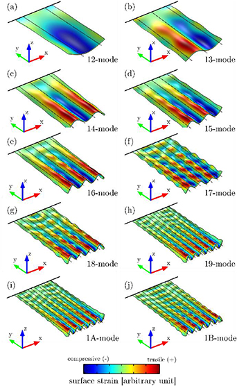
Figure 1. Illustration of a FEM eigenmode analysis for the first 10 orders (a)–(j) of the roof tile-shaped mode of single-side clamped plates (2524 × 1274 × 20 μm3). The dotted lines are a guide to the eye indicating the nodal lines of the particular mode shape.
Download figure:
Standard image High-resolution image
Figure 2. Schematics of the piezoelectric MEMS resonator fabrication process.
Download figure:
Standard image High-resolution imageThe SOI substrate is shown in figure 2(a) and consists of a 20 μm thin device layer, a 350 μm thick handle layer, a 500 nm thin buried SiO2 thin film and a stress-compensated oxynitride for passivation purposes. As the initial step of the fabrication process, a bi-layered 50/450 nm chromium/gold electrode is evaporated and patterned on top of the substrate as depicted in figure 2(b). To obtain proper patterning of the piezoelectric aluminium nitride layer a titanium hard mask is utilized as illustrated in figure 2(c). Subsequently, 1 μm thin piezoelectric aluminium nitride is sputter deposited (figure 2(d)) and a second 50/450 nm thin chromium gold electrode is evaporated (figure 2(e)), followed by a second 250 nm thin titanium hard mask as depicted in figure 2(f). Next, the aluminium nitride thin film is wet chemical etched using phosphoric (H3PO4) and hydrofluoric (HF) acid, resulting in a patterned stack of two chromium/gold electrodes sandwiching an aluminium nitride layer as shown in figure 2(g). To release the vibrating structure, the oxynitride passivation layers are locally removed by dry etching, followed by deep reactive etching processes of the device and handle layers. In both etching steps, the process stops at the buried SiO2 layer, as illustrated in figure 2(h). Next, the remaining SiO2 thin film is removed by a second wet chemical etching process using HF. This results in two chromium/gold electrodes sandwiching a piezoelectric aluminium nitride thin film on top of a released silicon resonator as illustrated in figure 2(i). For characterization purposes, a high precision wafer saw is used to dice the resonators in dies having a size of 0.6 × 0.6 mm2. Finally, the resonators chips are glued into 24-pin dual inline packages (DIP) and are wire bonded.
As depicted in figure 3, the rectangular electrodes are patterned, aiming at an optimized electrical read-out of the seventh order roof-tile shaped mode. In figure 4, the principle of the investigated electrode design is explained in more detail by a schematic cross-sectional view. The dashed lines illustrate the position of the nodal lines of the 18 mode, calculated by Euler–Bernoulli beam theory with free–free boundary condition as reported in [18]. This is a reasonable approach as in the latter study, the results of Euler–Bernoulli beam theory are compared those of FEM analysis and laser Doppler vibrometer measurements, showing a very good agreement in the prediction of nodal lines for all three methods. The spacing between the rectangular electrodes, as well as the distance to the tip edge of the plate are kept constant at 5 μm. As the boundary conditions along the width of the mode shape are considered free–free, the sign of curvature does not change across the two outer most nodal lines, such that the corresponding electrodes can be extended to the edge of the plate with again a 5 μm spacing resulting in an enhanced width compared to the inner electrodes, as illustrated in figure 4. The resonator shown in figure 3 is completely immersed in three model solutions. The corresponding parameters are listed in table 1. An Agilent 4294A precision impedance analyzer is used to electrically characterize the frequency response of the investigated resonators recording the electrical conductance G and the electrical susceptance B (see figures 4(a) and (b)). Thereby, the electrodes are electrically actuated such that the sign of the piezoelectrically generated mechanical strain in the area covered by one electrode fits to the sign of curvature of the mode shape as reported in [19]. Using such an actuation technique, very high electrical conduction peaks are obtained even when the plate is immersed in liquids. One drawback of this technique is that for every mode shape a resonator with optimized electrode design has to be fabricated.
Table 1. Parameters of the investigated model solutions at 24 °C—N1 and D5 are viscosity standards from Paragon Scientific. The speed of sound for all three model solutions is obtained with a Karl Deutsch 1076 K echo meter.
| Model solution | Density ρfluid | Dyn. viscosity μfluid | Speed of sound vc |
|---|---|---|---|
| — | (kg/l) | (mPa s) | (m s−1) |
| N1 | 0.774 | 1.00 | 1255 |
| Iso | 0.782 | 1.98 | 1133 |
| D5 | 0.835 | 4.89 | 1361 |
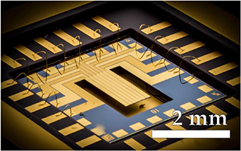
Figure 3. Optical micrograph of a piezoelectric MEMS resonator and a top view as inset.
Download figure:
Standard image High-resolution image
Figure 4. Schematic cross-sectional view on the MEMS resonator illustrating the electrode design on the plate support for the 18-mode. The dotted lines are a guide to the eye indicating the nodal lines of the mode shape.
Download figure:
Standard image High-resolution imageThe representative measurement shown in figure 6 is fitted by applying a least squares algorithm with Levenberg Marquardt error minimization. From the resulting fit, the resonance frequency fres and the quality factor Q are calculated using equations from [34],
Additionally, all resonators are characterized optically using a Polytec MSA-500 laser Doppler vibrometer. The observed mode shapes are used to clearly assign the electrically measured fres and Q values to the corresponding mode.
4. Results
In figure 5(a) the measured quality factors are shown as a function of mode order, for all the investigated fluids. A square root-like increase in the Q factors is observed up to the seventh mode order for the three liquids. For higher order modes, however, a significant decrease in the quality factor ( ) of 12%, 50% and 13% is detected at the critical mode number
  , starting at ncrit = 8 at 2.36 MHz in isopropanol followed by ncrit = 9 at 3 MHz for N1 and ncrit = 10 at 3.6 MHz for D5, respectively. A similar decrease in Q up to 40% was also reported in a study investigating devices of similar design [24]. In contrast to the latter findings, however, the decrease in Q between the three investigated liquids does not correlated with the differences in the density and speed of sound values as shown in table 1, and requires further investigations. For n > ncrit, no clear differentiation between the Q factors of the different liquids is observable. It has to be pointed out that at excitation frequencies above 3 MHz the investigated plate can be actuated at many different mode shapes being close in the corresponding resonance frequencies. This requires advanced multi-peak fitting, which again has a strong influence on the accuracy of the extracted Q values. Results obtained for the normalized resonance frequency
  are shown in figure 5(b). For n < ncrit, the fluid density has a dominant influence on the resonance frequency such that the largest angular resonance frequency ωres for each mode is observed in the least dense liquid. For n> ncrit, however, the speed of sound vc exerts a significant effect on the resonance frequency, with the highest resonance frequency occurring in isopropanol (vc = 1133 m s−1) followed by N1 (vc = 1255 m s−1) and D5 (vc = 1361 m s−1). These results are compared to the theoretical model of [13], where the critical mode number for beam-type resonators is calculated, as shown in equation (10). Equation (10) is obtained by equating the wavelength of sound waves in the fluid with the spatial wavelength of the vibrational mode of a cantilever beam. We adapt this approach to vibrational modes in cantilevered plates by numerically determining the eigenfrequencies and eigenmodes in vacuum using COMSOL Multiphysics. We performed a 2D-Fourier transform of the simulated eigenmodes and extracted the spatial wave vectors present in each mode. To better discriminate different wave vectors we symmetrized and zero-padded, i.e. extended the mode shapes with zeros, before Fourier transforming them. From the wave vectors, we determine the characteristic spatial wavelengths of the vibrational modes. The wavelength of a sound wave in a fluid λsound is equal to
  , where fsound is the frequency of the sound wave. We approximate fsound with the eigenfrequencies of the cantilevered plate and compare the sound wavelengths with the characteristic plate mode wavelengths for the first 50 mode numbers, as shown in figure 7. The sound wavelengths in isopropanol are generally the smallest for a given frequency while in D5 the wavelength is largest. However, the sound wavelengths are of the same order of magnitude at a given frequency. Above mode number 7, the largest spatial wavelength of the vibrational plate modes is in the order of magnitude of the sound wavelength. Above mode number 9, the sound wavelength is not larger than two times the wavelengths of the spatial plate modes. Thus, we expect significant sound dissipation for modes with a mode number larger or equal to 9. These results are in good agreement with the experimental results presented in figure 5. Furthermore, the increase in ncrit values from 9 in isopropanol to 11 in D5 is in excellent agreement to the differences in the corresponding speed of sound values listed in table 1.
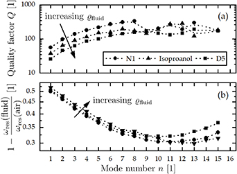
Figure 5. (a) Quality factor and (b) normalized resonance frequency as a function of mode number for N1, isopropanol and D5.
Download figure:
Standard image High-resolution image
Figure 6. Representative frequency-dependent characteristics of (a) the electrical conductance G and (b) the electrical susceptance B of a piezoelectric MEMS resonator, immersed in viscosity standard fluid D5 with a density of ρfluid = 0.835 kg l−1 and a dynamic viscosity μfluid = 4.89 mPa s at 24 °C.
Download figure:
Standard image High-resolution image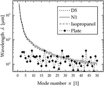
Figure 7. Comparison of the largest spatial wavelength in the simulated mode shapes (plate) and the wavelengths of sound waves in D5, N1 and isopropanol for different mode numbers n.
Download figure:
Standard image High-resolution image
5. Conclusions and outlook
Piezoelectric MEMS resonators represent a promising platform for various applications in liquid environment. Operated at the first few mode orders, the liquid can generally be assumed as a non-compressive fluid, as the acoustic wavelength in the liquid greatly exceeds the characteristic length of the fluid flow around the resonator. Consequently, the damping characteristics are dominated by viscous forces only. When operating at higher mode orders, however, the assumptions regarding the characteristic length have to be reassessed as with increasing modal number also the length scale of spatial oscillations decreases and the spatial wavelength of the beam will eventually set the characteristic length of the resonator. As a consequence, a second loss mechanism accounting acoustic radiation will drastically increase damping in the overall system, which has to be considered. The presence of this additional loss mechanism is not only dependent on the geometry of the resonator, but also on the physical properties of the liquid, being in the focus of this study. Therefore, piezoelectric plate-type MEMS resonators were fabricated and excited in the first 15 orders of a non-conventional bending mode in three liquids with dynamic viscosities ranging from 1 to 5 mPa s. Sound dissipation effects were observed by a decrease in the quality factor starting at the critical mode number 8 for the liquid with the lowest density of 0.774 kg l−1. For the other two liquids with densities of 0.782 and 0.835 kg l−1 sound dissipation started at mode number 9 and 10, respectively. These results are in excellent agreement to theory as with an increase in densities also the speed of sound in the particular liquids increases to values of 1133, 1255 and 1361 m s−1. A larger wavelength of the sound wave results in liquids with a higher density, shifting the critical mode number to higher values. These experimental results were compared to both an analytical model and FEM simulations for plate-type resonators in liquids, showing good agreement. It has to be pointed out, that sound dissipation starts not just at the coincidence point, where the sound wavelength is equal to the wavelength of the beam, but rather as early as these two parameters are in the same order of magnitude. A strong decrease in quality factor up to 50% were recorded at the critical mode number, showing that about half of the energy put into the system is dissipated via acoustic radiation. This drastic increase in damping is unwanted in most sensing scenarios and has to be considered especially for low dense liquids, as this additional loss mechanism already contributes at lower mode orders. However, noticeable differences in the quality factor drop was observed for the investigated liquids, which requires further investigations. To prevent sound radiation, we recommend increasing the width of the resonator structure, as with an increase in width the resonance frequency of the investigated modes are reduced and therefore the wavelength of the sound waves is increased, which shifts the critical mode number to higher values. However, the acoustic radiation capability may also be beneficial for other measurement principles in liquids such as micro-acoustic wave sensors.