

Abstract
Contact pressure at the workpiece/tin lap interface during full-aperture polishing is of great significance to workpiece's material removal process. To promote the determinacy and efficiency of polishing process, a novel wireless contact pressure measurement system is developed. Further, the contact pressure distribution map is solved by the interpolation algorithm using the acquired contact pressure data at workpiece/ tin lap interface. Subsequently, a material removal amount model within given polishing time is proposed. Based on this model, process parameters are optimized with the genetic algorithms using contact pressure distribution map under specific workpiece's initial surface figure and polishing conditions. Compared with random process parameters, the optimized process parameters can greatly improve the accuracy and convergence efficiency of workpiece's surface figure in full-aperture polishing with tin lap, which is validated by the polishing experiments.
Export citation and abstract BibTeX RIS
Large optical flats with high precision surface figure and low sub-surface damage play an essential role in telescopes, interferometers and high-power laser facilities.1 Fabrication of such highly precise surfaces are generally through grinding and polishing to achieve a nanoscale accuracy for the final surfaces through multiple iterative fabrications.2,3 Optical polishing processes are typically classified into full-aperture polishing processes in which the polishing tool is substantially larger than the workpiece being polished, and sub-aperture polishing processes that use a small tool to remove local materials.4 Full-aperture polishing processes take the advantage of high material removal efficiency and restraining the mid-spatial frequency errors (i.e., the tool masks generated in sub-aperture polishing processes). The polishing layer used in the full-aperture polishing processes is commonly made from tin, Teflon, polyurethane and polishing pitch.5–8 Tin lap with high rigidness and excellent performance in keeping the accuracy of surface shape is suitable for high precision polishing hard brittle crystals and optical glasses. However, how to make the convergence process of workpiece's surface figure with tin lap more deterministic, more economical and less iterative still remains a tough problem.
Researchers have tried to develop the polishing machine, reveal the mechanism of material removal and improve the output surface quality during polishing of hard brittle materials with tin lap. Namba et al. designed a float polishing machine with the tin lap of 460 mm in diameter, and a sharp diamond tool was used to flatten the lap surface as well as cut polishing slurry channels.7 As for the temperature rise measured by Baak during polishing with tin lap, the temperature control of polishing slurry, tin lap and sample was added onto the float polishing machine.9 In respect of the material removal mechanism, Hader and Weis investigated the polishing process of sapphire with float polishing technique developed by Namba and proposed a hydrothermal wear model to explain the material removal.10 Conversely, Werner and Weis studied the wear residue from polishing sapphire with silica aquasol and concluded that the abraded freed aluminum atoms finally chemically bond in the colloidal silica clusters.11 Hasegawa et al. simulated the polishing particle collided with one unit cell of the substance at different surfaces and found that polishing rate at the (110) surface of Si was faster than (100) surface.12 With regard to polishing experiments, Bennett et al. polished six different optical materials on the abovementioned float polishing machine to determine its suitability for producing super smooth surfaces of different optical materials.13 In addition, tin lap was used to polish calcium fluoride (111) single crystals, and there were small atomic steps on the polished surface with almost no sub-surface damage.14 Meanwhile, the hard-disk magnetic head was precisely polished on the tin lap by lapping and nano grinding, and ultrasonic vibration was introduced to reduce the magnetic recording pole tip recess.15,16 For large flat fused silica optical glass, there is little information about the surface figure control during full-aperture polishing with tin lap.
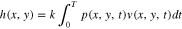
The workpiece's material removal rate at any arbitrary polishing site during polishing can be quantitively described by:
where the dh(x, y, t)/dt is the local average material removal rate during a period of polishing time, k is material removal coefficient, which is assumed a constant under given polishing conditions, p(x, y, t) is the instantaneous contact pressure and v(x, y, t) is the instantaneous relative velocity at the given site.17 To great extent, the nonuniformity in contact pressure on the whole polishing surface dominates the nonuniform removal of workpiece materials. Furthermore, polishing lap's surface shape error plays a vital role in contact pressure distribution. Liao et al. measured the surface shape error with laser displacement sensor in a spiral path and improved the surface shape error of polyurethane pad and pitch lap.4,18 Whereas the pitch of the spiral measuring path is about tens of millimeters, it will introduce considerable error in correcting polishing tool's surface shape error. Or rather, the polishing tool's surface can't be conditioned to be an ideal absolute plane, which impacts the accuracy and convergence efficiency of workpiece's polished surface figure. The surface deformation generated during tin lap polishing is negligible compared with polyurethane pad resulted from wear and pitch lap induced by rheologic characteristics. Thus, an attempt is inspired to measure the contact pressure distribution map at workpiece/tin lap interface and optimize the process parameters to promote polishing accuracy and efficiency.
In the following, the contact pressure distribution at the workpiece/tin lap interface will be wirelessly measured with a novel measurement system and processed by interpolation algorithm. Then, a material removal amount model within given polishing time will be proposed. By combining this model with genetic algorithms (GA), process parameters will be optimized for higher accuracy and efficiency under specific workpiece initial surface figure and given polishing conditions. The random process parameters and optimized process parameters will be used to polish two groups of workpieces with almost identical initial surface figures. Moreover, polishing convergence efficiency of surface figures will be defined to evaluate the polishing experiments with different process parameters.
Experimental
Experiment device and polishing conditions
The polishing experiments were conducted on the KPJ-1200 full-aperture polishing machine tool (Beijing Weina Precision Machinery Co., Ltd, China), as schematically shown in Fig. 1. The granite platen was covered with a tin lap (φ1200 mm  12 mm in thickness, Hyprez, Engis, USA). The workpiece (430 mm
  430 mm
  40 mm, fused silica) to be polished was clamped by a special designed fixture mounted on the work shaft. Before polishing, the lap's surface shape error was measured with the method proposed by Liao et al. and conditioned with a diamond turning tool fixed on the conditioning shaft to improve the surface shape error [4]. The translation of the work shaft and conditioning shaft along the gantry was driven by a servo motor with ball screw. Additionally, radial and circumferential grooves (2°, 2 mm in width, 50 mm spacing) were cut onto the tin lap surface with the diamond turning tool. During polishing, the platen and the workpiece was driven by servo motors to rotate anticlockwise. Simultaneously the abrasive slurry (CeO2, ∼0.5 μm, universal photonics, New York, America; flow rate: 1.6 l min−1) was injected onto tin lap surface and transported to polishing site by the slurry channels. The temperature and the humidity at the ambient were 21.3 °C and 65.2% RH respectively. Subsequently, the workpiece's surface figure was measured on the laser interferometer (32'', Zygo, USA) at 21.7 °C and 37.2% RH.

Figure 1. Schematic image of a full-aperture polishing machine with tin lap.
Download figure:
Standard image High-resolution imageMeasurement system of contact pressure distribution map
After the tin lap was conditioned by the diamond turning tool, a novel measurement system was developed to measure the contact pressure P(xp, yp) at the workpiece/tin lap interface under given polishing conditions. This system used a pressure transducer (piezoelectric, resolution: 1.3 Pa, bonded with a small fused silica block as detection head, φ15 mm  1 mm in thickness) fixed into the granite transducer fixture (120 mm
  120 mm
  31.4 mm, a hole 25 mm in diameter
  31.4 mm in thickness), as shown in Fig. 2. It's worthwhile noticing that the thickness of the granite transducer fixture was designed to produce an equal theoretical contact pressure at its bottom surface to that at workpiece. Besides, the bottom surface of the granite transducer fixture was pre-polished to a peak to valley (PV) < 0.5 μm with polyurethane polishing pad. Therefore, the measured contact pressure by the pressure transducer can be regarded as the interface contact pressure P(xp, yp) when the workpiece was contacting with the same area on the tin lap. The ball spring screws mounted on the limit stop were used to frictionlessly support the side face of the granite transducer fixture to avoid overturning moment. And the limit stop was fixed into the conditioning shaft by the fastening screw.

Figure 2. Schematic image of wireless contact pressure distribution map measurement system.
Download figure:
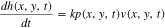
Standard image High-resolution imageA Cartesian coordinate system is fixed on the tin lap surface, where the origin O is set at the geometric center of tin lap surface. The z axis is oriented from the origin and vertical to the tin lap surface. Further, the x axis is oriented from the origin and parallel to the gantry's side surface. Then, the y axis is oriented from the origin and the direction is determined by right-hand rule. During measurement, the tin lap was anticlockwise rotating around its geometric center O with constant angular velocity w1 (π/3) and the granite transducer fixture was sinusoidally reciprocating along the radial direction of the tin lap. Hence, the instantaneous coordinate (xp, yp) of the measured point in the tin lap coordinate system can be expressed as:
where the r is the radius of the tin lap (600 mm), l is the distance between the center of the pressure transducer and the outer edge, v is translation speed of the granite transducer fixture (2 mm s−1), A is the amplitude of sinusoidal reciprocating motion (5 mm), wi represents the angular velocity of the ith measurement, which is:
and α is the initial angle between the starting location of the ith measurement and the x axis in the tin lap coordinate system.
During its measurement, the detection head of the pressure transducer was always contacting with the asperities on the tin lap surface and acquiring the contact pressure P(xp, yp) at the local contact area. Synchronously, the measured data of contact pressure P(xp, yp) was wirelessly transferred to PC by LAN. Next, the acquired data was filtered to eliminate abnormal value and averaged at the same location in the tin lap coordinate system. Finally, the contact pressure distribution map was solved by interpolation algorithm.
Calculation of Material Removal Amount and Process Parameters Optimization
Material removal amount of any arbitrary point on the workpiece
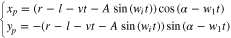
As shown in Fig. 3, a Cartesian coordinate system is fixed on the workpiece polishing surface, of which the origin Ow is set at the geometric center of the workpiece polishing surface. The xw (yw) axis is oriented from the origin Ow and parallel to the x (y) axis in tin lap coordinate system described in Fig. 2, respectively. Assumed there is any arbitrary point P1 on the workpiece, where the initial polar angle and radius in the workpiece coordinate system are β and r0. The distance between the O and Ow is e. During the polishing, the tin lap and workpiece is continuously rotating around O and Ow with constant angular velocity w1 and w2, and the workpiece is reciprocating concurrently along the radial direction of tin lap in sinusoidal mode. The instantaneous coordinate (x, y) of specific point P1 in tin lap coordinate system can be formulated as:
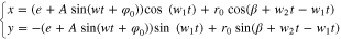
where w and φ0 represent the angular velocity and initial phase angle of the sinusoidal reciprocating motion.

Figure 3. Kinematic analysis for the full-aperture polishing with tin lap.
Download figure:
Standard image High-resolution imageThe total material removal amount h(x, y) of the point P1 within the polishing time T can be obtained from Eq. 1:
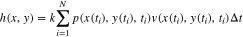
When the polishing time T is discretized with a miniature interval (Δt), the Eq. 5 can be written as:
And

If the discretized time interval is minimum enough, the arc length Δs(xw, yw, ti) can be derived as:

where x'(ti) and y'(ti) are the first derivative of the instantaneous coordinate (x(ti), y(ti)) of specific point P1 in tin lap coordinate system. In terms of instantaneous pressure p(x(ti), y(ti), ti), the polishing time ti is substituted into Eq. 4 to solve the instantaneous coordinate (x(ti), y(ti)) of P1 in tin lap coordinate system. Then, the instantaneous contact pressure p(x(ti), y(ti), ti) can be sought out according to the measured contact pressure distribution map . The material removal coefficient k was assumed to be an constant, which was calculated by averaging the values of five samples (fused silica, 100 mm in diameter and 10 mm in thickness) with Eq. 1 under given polishing conditions. Consequently, the material removal amount h(x, y) of given point within polishing time T can be obtained.
Optimization of process parameters
To improve the convergence efficiency and accuracy of workpiece's surface figure, the process parameters are optimized with an artificial intelligence algorithm.
Genetic algorithms (GA)
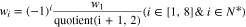
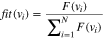
GA is inspired by the process of natural evolution and commonly used to search optimal solutions for multiple influencing factors problem. Figure 4 depicts the flow chart of operation processes for GA. Firstly, the random individuals v1,v2,...,vn are coded into chromosomes composing a specific population g(i), and these individuals must satisfy the given constraints. Then, the fitness fit(vi), which is calculated by the defined fitness function F(vi), of each chromosome in the specific population g(i) is used to evaluate each individual:
Next, a new population g(i+1) is generated by bio-inspired operators such as selection, crossover and mutation to avoid falling into local optimal solution.19 Finally, if there is any chromosome g(io, jo) approaching the optimization target or reaching maximum iteration times imax, the chromosome g(io, jo) is selected as the optimum individual. Or the new population g(i+1) is used for the next iteration until meeting any cycle termination conditions.

Figure 4. Flow chart of operation processes for GA.
Download figure:
Standard image High-resolution imageMulti-objective optimization based on GA
GA optimization was adopted to search optimal combination of process parameters in this research. The GA started with a population of random individuals in the process parameters of e, A, w, w1, w2, φ0 and θ0, which is the angle between the xw axis in the workpiece coordinate system and x axis in tin lap coordinate system. The problem of this optimization is how to minimize the PV of workpiece's surface figure and maximum the convergence efficiency. Accordingly, the optimization objective function was:


where the O1 and O2 are the minimum and maximum values of the workpiece's surface figure and convergence efficiency.
In this research, the multi-objective optimization problem is simplified to a single objective optimization problem by applying the weight sum method. In the practical full-aperture polishing process, the surface figure is more important than convergence efficiency.so the weighting factors of the surface figure and convergence efficiency are 3/4 and 1/4, respectively. The objective function of the simplified single objective optimization problem is given by:

and the value scopes of the e, A, w, w1, w2, φ0 and θ0 are listed in Table I.
Table I. Value scopes of process parameters.
| Variables | Scope |
|---|---|
| e (mm) | [−350, −250] |
| A (mm) | [−40, 40] |
| w (rad s−1) | [π/60, π/10] |
| w1 (rad s−1) | [π/15, π] |
| w2 (rad s−1) | [π/6, 2π/3] |
| φ0 (rad) | [−π, π] |
| θ0 (rad) | [−π, π] |
Before polishing, the surface figure of the workpiece to be polished was measured on the laser interferometer. Taking the lowest point pw as the reference point, the expected material removal amount m(x, y) at any point on the workpiece is equal to the height relative to the point pw. Theoretical value of the material removal amount h(x, y) at the same point can be calculated by the proposed model . As a result, the O1 is:

and O2 is:

The optimization of process parameters using GA is implemented on the MATLAB 2014a with programmed codes, where the setting conditions are as follows: 100 generations, population size of 180 with roulette selection function, scattered crossover probability of 0.7 and Gaussian mutation probability of 0.02.
Results and Discussion
During full-aperture polishing with tin lap, the contact pressure at the workpiece/tin lap interface is dominated by the lap's surface shape error. When the granite transducer fixture is contacting with tin lap, the theoretical average contact pressure at lap/granite transducer fixture interface is equal to that at lap/workpiece interface. Thus, it's reasonable to consider that the contact state between the workpiece and the pressure transducer contacting with the same site on the tin lap is almost same. Further, the contact pressure acquired by the pressure transducer is equal to that at workpiece/lap interface. The acquired contact pressure distribution reflects the difference of lap's surface shape error distribution. After measuring the contact pressure distribution map on the tin lap with the proposed method , several polishing experiments were conducted on the KPJ-1200 polishing machine with tin lap under the given polishing conditions . Subsequently, a group of random process parameters and the optimized process parameters solved by GA were utilized to polish the two workpieces with almost identical initial surface figures, respectively. These polishing experiments were continuously polished on the same tin lap without conditioning.
Figure 5 illustrates the contact pressure roughly remains steady at the circumferential direction of the tin lap; on the contrary, the contact pressure violently fluctuates between 110.5 Pa and 10407.6 Pa along the radial direction of the tin lap. When the tin lap was conditioned with the diamond tool, the diamond tool fixed on the conditioning shaft slowly translated along the gantry and the tin lap rotated at constant speed. As a result, the lap's surface shape error is rotational symmetric, which accounts for the spatial distribution of contact pressure. Besides, the contact pressure increases sharply near the edge of the tin lap.

Figure 5. Measured contact pressure distribution map at workpiece/tin lap interface.
Download figure:
Standard image High-resolution imageIn simulation, accumulated material removal amount h(x, y) was calculated according to the proposed material removal amount model. By subtracting the accumulated material removal amount h(x, y) from the expected material removal amount m(x, y) at the same site on the workpiece polishing surface, the workpiece's residual PV varied with polishing time can be obtained. The optimum polishing time To for the optimized process parameters was determined while the workpiece's residual PV started to inversely increase. In order to compare the effect of the optimized process parameters with random process parameters, the polishing time Tr of the process using random parameters was the same as To.
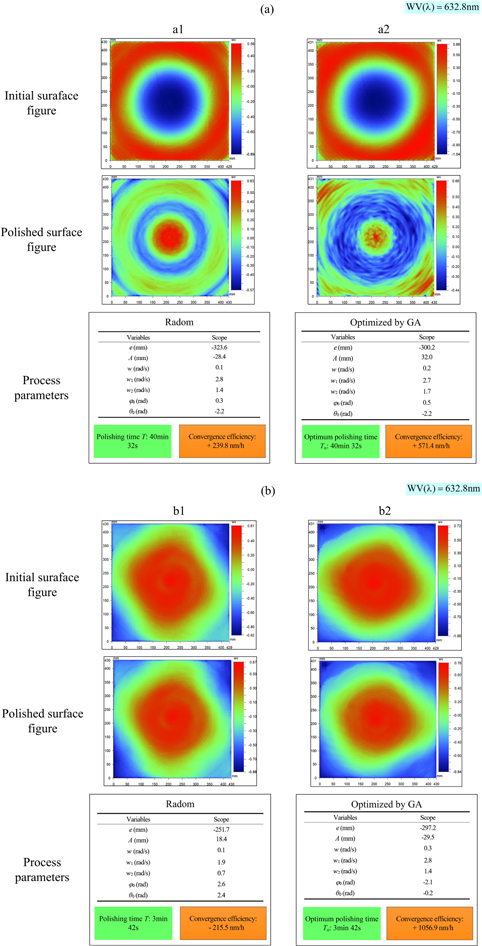
Figure 6 shows the initial surface figures, polishing process parameters, polished surface figures and the convergence efficiencies at different polishing processes. The convergence efficiency η of any polishing process is defined as:
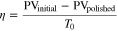
where PVinitial and PVpolished represent the PV of the workpiece's initial and polished surface figure. Compared with the random process parameters, the convergence efficiency of the polishing process using the optimized process parameters are both greatly improved in the two groups of experiments. In the group (a), the convergence efficiency of experiment a2 is twice as much as that of a1, which suggests the optimized process parameters based on the GA can greatly improve the accuracy and convergence efficiency of the workpiece's surface figure. However, the convergence efficiency of b1 is negative, which illustrates the workpiece's surface figure deteriorated after polishing. Although the convergence efficiency of b2 is positive and very high, the improvement in surface figure compared with the initial is very little.
Figure 6. Initial surface figures, polished surface figures and process parameters in the different polishing experiments.
Download figure:
Standard image High-resolution image
It's noticeable that the optimum polishing time for the workpiece polished in group (b) was only 3 min 42 s. If the polished time cycle is set six hours as that in practical polishing process, the polished surface figure may be far worse than that in b1 with random process parameters. In other words, the tin lap with the measured contact pressure distribution isn't suitable for the workpiece with initial surface figure in group (b). Only by conditioning the tin lap's surface shape error with the diamond turning tool can this situation be improved. Consequently, the process parameters optimization based on the GA coupling the proposed material removal amount model with contact pressure distribution map can greatly improve the determinacy and efficiency during the full-aperture polishing with tin lap. Moreover, the optimum polished time T0 can be used to prejudge whether the tin lap needs to be further conditioned before polishing.
Conclusion
A novel wireless pressure measurement system has been developed to acquire the contact pressure, which ranges from 110.5 Pa to 10407.6 Pa, at the workpiece/tin lap during full-aperture polishing. By combining the single point material removal amount and GA, the optimal process parameters are searched for maximum convergence efficiency under given polishing conditions and contact pressure distribution. The convergence efficiencies of the two comparison groups with either optimized process parameters or random process parameters indicate effectiveness of the proposed method.
Acknowledgments
Funding by Science Challenge Project (NO: TZ2016006-0501) of china.