3D Building Façade Reconstruction Using Deep Learning


1
Department of Computer Science, University of Crete, 70013 Heraklion, Greece
2
Foundation of Research and Technology Hellas (FORTH), 70013 Heraklion, Greece
3
School of Electrical and Computer Engineering, Technical University of Crete, 73100 Chania, Greece
4
ATHENA Research and Innovation Information Technologies, 15125 Marousi, Greece
*
Author to whom correspondence should be addressed.
†
These authors contributed equally to this work.
ISPRS Int. J. Geo-Inf. 2020, 9(5), 322; https://doi.org/10.3390/ijgi9050322
Submission received: 24 March 2020
/
Revised: 1 May 2020
/
Accepted: 11 May 2020
/
Published: 13 May 2020
Abstract
:In recent years, advances in computer hardware, graphics rendering algorithms and computer vision have enabled the utilization of 3D building reconstructions in the fields of archeological structure restoration and urban planning. This paper deals with the reconstruction of realistic 3D models of buildings façades, in the urban environment for cultural heritage. The proposed approach is an extension of our previous work in this research topic, which introduced a methodology for accurate 3D realistic façade reconstruction by defining and exploiting a relation between stereoscopic image and tacheometry data. In this work, we re-purpose well known deep neural network architectures in the fields of image segmentation and single image depth prediction, for the tasks of façade structural element detection, depth point-cloud generation and protrusion estimation, with the goal of alleviating drawbacks in our previous design, resulting in a more light-weight, robust, flexible and cost-effective design.
1. Introduction
The constant differentiation of the number and architectural characteristics of buildings in a city, has highlighted the necessity of building documentation in order to better organize, plan and control the structural specifications of each city. The utilization of three-dimensional (3D) photo-realistic reconstructions of buildings allows the documentation of the architectural (appearance) characteristics of each building. When accompanied by a detailed reference of the location and dimensions of the structure, offers a complete overview of all the building’s features. However, the generation of 3D photo-realistic 3D building façade reconstructions is a challenging task since building façade designs vary in the number and architectural complexity of their structural components. This attribute becomes a severe issue in older cities in which historical and modern building designs co-exist, encapsulating decades of architectural design trends. An ideal automated 3D building façade reconstruction approach designed for the purpose of providing photo-realistic 3D building façade reconstructions for building documentation, should exhibit robustness and flexibility against different design characteristics and be as much as resource and computational cost-efficient as possible.
Over the last decade, numerous 3D building reconstruction approaches have been developed that exploit terrestrial laser scanning technologies [1,2] and close-range photogrammetry [3,4] to produce building façade maps and 3D point-clouds, which when combined appropriately are able to produce photo-realistic reconstructions of the structure. Of the two directions, the most widely-used is the utilization of the laser scanning technology [5], known as LIDAR (LIght Detection And Ranging), due to the density of the generated 3D point-clouds, and the precision in the relative dimension estimation as well as structural façade component details of the building. Nevertheless, the utilization of laser scanning data alone is not sufficient to produce photo-realistic and with high precision reconstructions. The technology is highly susceptible to the existence of gaps along laser points attributed to surface or material driven laser distortion effects. These gaps lead to reconstruction distortions in the form of positional offsets between the represented and the actual structure edge positions. Moreover, to obtain photo-realistic and georeferenced results, textures must be mapped from images to the geometric models [6,7] and to be registered to the corresponding georeferenced data points. The data post-processing necessity increases the computational complexity of laser-based approaches. This factor in conjunction with the high cost of the laser scanning equipment limits the flexibility and wide availability of laser-based reconstruction systems.
As a solution, recent methods have attempted to extract as much information as possible from additional sensors, such as geodetic stations or optical camera sensors. Of the two, image sensors have been the most utilized due to the large amount of existing data, plethora of availability sensors with high resolution capabilities and wide range of cost. Image data have been exploited, besides as a texture source, to generate dense depth point-clouds, using an approach known as Structure from Motion (SFM) [8]. The image-driven point-clouds are then, either combined with the laser scanning data [9,10,11] or used solely [12,13] to construct dense and photo-realistic reconstructions.
Regarding building façades, image data have been utilized as the main information source for the detection of structural components, such as windows, door, ledges, etc. They need to be isolated for further assessment of their attributes, such as protrusion, more detailed extraction of textures, explicit estimation of their relative position, architectural design estimation, etc. To detect and isolate the structural elements, existing works initially identify relevant image features, either using hand-crafted descriptors [14,15,16] or more recently deep learning [17,18,19], that represent the element’s inherent characteristics. The final detection of the regions that are most likely to contain each structural element is performed either with the training of deterministic classifiers, such as Support Vector Machines (SVMs), or in conjunction with feature learning in an end-to-end pipeline using Convolutional Neural Network (CNN) designs.
Compared to the aforementioned approaches, our current and earlier works on the topic of photo-realistic 3D building façade reconstruction, are amongst the few that attempt to exclude the dependence on laser scanning data [12,13]. Our framework combines image and georeferenced data to extract meaningful attributes for the façade’s structural elements (positional, appearance and depth-related features). The crude 3D point-cloud estimates, in a format suitable for import into graphic rendering and development platforms, such as Unity 3D game engine, allows the creation of a photo-realistic georeferenced 3D model of the viewed structure. The current version of our work exploits the recent advances on image segmentation and depth prediction using deep learning, to increase the robustness and performance of the parts involving the façade element detection, attribute estimation and the initial image-driven building façade depth point-cloud generation.
The sections of the article are organized as follows. In Section 2 the proposed approach is presented in more detail, initially providing an overview of the previous version of our framework, highlighting the limitations and drawbacks, followed by the solutions and theoretical aspects of the new additions/alterations. Section 3 presents results and comments regarding the performance of the proposed approach. Finally, Section 4 provides conclusions on the proposed methodology and possible future improvements that can further increase the robustness and overall performance.
2. Proposed Method
The present work is considered to be an extension to our previous work, with the goal of refining and strengthening the framework design. We begin with an overview of the overall approach introduced in [20], presenting its advantages, limitations and highlighting the parts of the methodology that the present work aims to improve. The contributions of the present paper lie in eliminating the limitations of our previous approach. (a) By introducing an auto-encoder neural network architecture for depth estimation using a single RGB image instead of a stereoscopic image sensor rig design, which can potentially increase the flexibility and decrease the overall cost of our framework. (b) By incorporating a deep learning-based façade segmentation stage based on generative adversarial networks, enabling for more scalable and robust façade element detection. (c) By integrating computational geometry techniques and point cloud processing algorithms to produce a detailed reconstructed 3D surface, enhancing the automation and adaptability of the suggested workflow.
2.1. Fusing Georeferenced and Stereoscopic Image Data for 3D Building Façade Reconstruction
In [20] we introduced a multi-modal 3-D building reconstruction approach that combined information from image sensors and ground control points. The motivation behind the approach stemmed from the assumption that the pipeline of a 3D building model reconstruction system could be simplified and become independent of laser-based depth sensors, by replacing them with stereoscopic image sensor systems for the generation of crude reconstructions. The reconstructions are refined with the combination of the 3D approximation with estimated morphological attributes extract from georeferenced data and morphological image processing techniques applied to the RGB images.
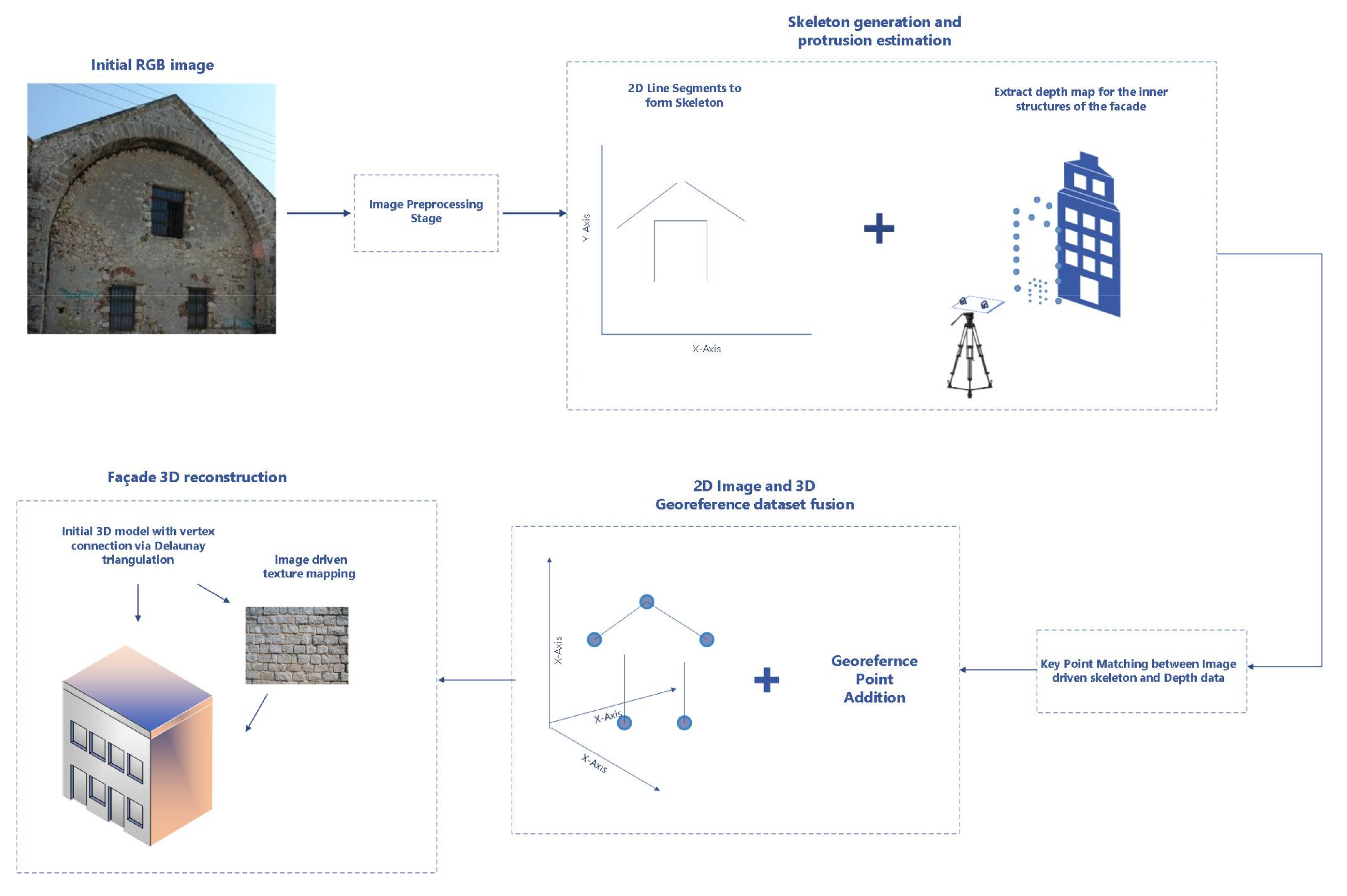
In more detail, the initial stage of our approach involved the generation of the outer-skeleton of a mosaic building view, using morphological image processing methods. The mosaic view was produced by stitching together multiple overlapping images of the building, in order to accommodate for large structures. Subsequently, in the second stage of our pipeline, a georeferenced 3D point-cloud was generated, by associating the 2D skeleton (connected line-segments generated from the façade views) from the previous stage with existing georeferenced point data of the building. The 3D point-cloud served as an initial crude 3D building reconstruction. In the third stage, the 3D reconstruction was further refined with façade structural element incorporation, such as windows or doors, whose location and protrusion were generated using image processing techniques. These techniques enabled the detection and segmentation of the structural elements from RGB-D image data provided by the image sensors. Depth information was acquired using a stereoscopic camera rig. Finally, the generated 3D reconstruction was further refined with the addition of textures sourced from the image data. The overall pipeline of our approach is depicted in Figure 1. For more details about the methodology please refer to [20].
The proposed methodology was modular, simple and low-cost. However, there existed key requirements and potential limitations which reduced its robustness and capabilities. As most prominent we can consider, (a) the requirement of a stereoscopic rig for depth estimation, (b) the hand-crafted methodology for the detection and segmentation of façade structural elements, and (c) the separate, not automatic incorporation of the detected feature protrusion data in the 3D data set at a later stage. In this paper we attempt to provide solutions to these issues, with the goal to further increase the robustness, automation and cost effectiveness of our framework.
2.2. Depth Estimation Using a Single RGB Image
Recent advances in deep learning have lead to the rise of methodologies that provided solutions to problems considered to be ill-posed and unsolvable up until now. One such problem is single image depth estimation (SIDE), which is considered as an ill-posed problem since an infinite number of distinct 3D scenes can be the source for a single 2D image. However, exploiting the deep neural network (DNN) capabilities several methods have been proposed that attempt to solve this problem, with considerable accuracy and efficiency ([21,22]).
Following these advances, we opted on using the work of Laina et al. [21] to extract the depth maps and formulate the corresponding 3D point-clouds. The selection of this approach was based on the following attributes. The deep architecture design is light-weight, allows for end-to-end training, achieves top-ranking scores on both indoor and outdoor depth map estimation data sets. It was trained for and finally, according to the authors, the model can achieve real-time performance.
The architecture presented by Laina et al. [21] based on Fully Convolutional Residual Network (FCRN), which will be referred from now on as FCRN-Depth, is essentially an auto-encoder DNN that uses Residual Network (ResNet-50) [23] as the encoder network, and a custom DNN architecture for the decoder network. Regarding the decoder network, the authors introduced and structured the architecture design with a set of up-projection blocks. Each block consists of a sequence of un-pooling, convolution layers enriched with residual connections that enables the flow of high-level information as the size of feature maps increases. This attribute is the key factor that differentiates the specific architecture from standard decoder designs. This relies only on standard up-sampling layers to increase the output resolution, and allows for more accurate depth prediction.
The learning process in FCRN-Depth involves the minimization of the mapping discrepancy between the estimated depth-map and the ground-truth, which was expressed in the paper using the reverse Huber loss [24]. The authors opted for this loss function instead of a classic euclidean norm due to the observation of heavy-tailed distribution of depth values in the examined data sets, which indicated that the effect of boundary or outlier values must be considered.
Finally, compared to the use of a stereoscopic approach the FCRN-Depth has the following advantages and limitations. As for the cost of the equipment it is simple that the equipment requirement is reduced to a single high resolution image sensor, reducing the total cost. In addition, in terms of depth prediction quality, a stereoscopic approach leads to better and even more rigorous estimates of the overall scene. However, as we will show in Section 3, when the estimates are used to determine the relative depth of specific building elements in contrast to the overall building the difference has little impact for simple yet realistic 3D reconstructions.
2.3. Façade Structural Element Detection
Our previous work was limited to detecting windows and doors on the façades of buildings based on shape characteristics and using candidate site suggestions generated by an active contour methodology. Specifically, provided that these structural components are usually rectangular, the approach combined a rectangle approach with a non-zero point population criterion to detect the corresponding structural component candidates. This approach was, however, restricted by the shape assumption, and applied to specific building façade designs and only to two particular structural component classes, windows and doors, without explicit discrimination between them. Moreover, the success of detection was widely affected by output of the region proposal stage which was based on an active contour approach [25]. The performance of the active contour approach is heavily depended on the initialization stage of the method, as well as the texture of the building façade. Dense and stone wall textures (mainly found in older buildings) lead to over-segmented regions, which can potential impede the algorithm from successfully completing the segmentation in the predefined epoch number.
As a solution to the aforementioned limitations and in order to increase robustness, flexibility to deploy more building structural components we decide to use a DNN for façade structural component detection. There exist a number of deep learning building façade component classification approaches which can roughly be grouped into two categories based on the general core network designs. The first category consists of approaches that follow a pixel-wise classification employing auto-encoder network designs to perform semantic segmentation ([19,26]). The second consists of approaches that reformulate the problem as an instance detection task and re-purpose object detection and image segmentation neural networks to the specific task using transfer learning ([27]). However, this learning direction is not flexible and not relevant to existing data sets since detection-oriented neural networks require bounding box annotations for each structural component class, a characteristic that is absent from existing building façade component segmentation data sets.
To relieve our framework from the instance bounding box annotation constraint and increase its learning flexibility, we followed the modelling direction of the first category. To this end, we opted on using a generative adversarial network (GAN) architecture, which generates the segmented façade component image. Such network does not require label or bounding box annotations, and can be easily trainable for tasks that involve mapping data to lower dimensional spaces, like in our case from a 2D RGB image to a finite number of classes. In addition, compared to mainstream auto-encoder designs it does not require the incorporation of elaborate de-convolution approaches such as dilated convolutions ([26]) or the introduction of predefined shapes into the learning loss function ([19]) to produce accurate segmentations for the problem of façade parsing.
Instead of designing and training from scratch a GAN for the task of generating building façade component segmentation images, we opted on using Pix2Pix GAN architecture [28]. The network design and layer specifications were maintained the same with minor changes, presented in the follow-up section, to adapt the network output to the specific task. In brief, Pix2Pix, as every GAN, consists of two sub-networks, (a) the generator network, G, which is an auto-encoder network whose task is to produce a building façade segmentation image to the desired class set, with input the raw RGB image, and (b) the discriminator network, D, which is a relatively simple DNN, that is insertet with the generated building façade segmentation image and whose task is to decide whether this image is real or fake (i.e., generated by another network). The goal in a GAN is to fool the discriminator, and the learning process involves minimizing the following loss:
The GAN loss consists of two components: (a) a data loss, , which aims to train the generator network to produce an output to classify it as real, and, (b) a regularization loss, , usually an L1 or L2 norm, whose purpose is to force the output of the generator to be as close as possible to a real/expected appearance of the ground-truth image.
For our task, Pix2Pix was retrained from the beginning using the eTRIMS Image Database [29], which consists of eight classes, namely being sky, building, window, door, vegetation, car, road, and, pavement, of which three belong to façade elements. It is simple that we can replace eTRIMS with any façade dataset to increase or decrease the number of component classes that need to be identified. For example, CMP Façade Database [30], can be considered as a better alternative as it mainly consists of façade element classes.
Utilizing Pix2Pix Façade Segmentation in an Automated 3D Façade Reconstruction System
In order for an automated 3D building façade reconstruction system to produce photo-realistic and precise reconstructions information, the relative dimensions and protrusion of each façade element at an instance level must be available. In a deep learning fashion, an instance-based object detection network, such as Mask-RCNN [31], can be incorporated after the pixel-wise segmentation Pix2Pix architecture. Compared to classic hand-crafted instance detector designs, an instance-based object detection DNN is more precise and flexible, in order to train such network architectures bounding box annotations is required. However, the majority of existing façade segmentation data sets do not provide such information. Since the number of instance classes and their morphological attributes (shape and geometry) are constrained (doors, windows and ledges have finite designs and specific shape geometry) we retained the classical hand-crafted detector design that we introduced in our earlier work [20]. Our design combines a blob detection approach with a rectangle fitting approach, under an element rectangle shape assumption, in order to isolate for each façade element class the existing instances.
2.4. Creation of the Georeferenced Feature Infused 3D Façade
The previous approach dealt with the incorporation of heterogeneous data sources in the workflow. A mapping scheme was utilized in order to combine 2D image data with 3D spatial information, which involved the creation of a fictitious space aiding the assignment of the third (depth) coordinate. Furthermore, the inclusion of depth based protrusion estimation was implemented at a later stage, in the already georeferenced enhanced building skeleton 3D data set. The approach consisted of consecutive but, at times, separate steps. Specifically, the diverse information sources required a fusion process stage and the inner feature protrusion refinement step was performed as an extension to the creation of the building skeleton. This approach although highly effective, could be enhanced by automation.
The newly adopted 3D reconstruction pipeline focuses on processing the image-based DNN results in an adept manner in order to generate a feature infused 3D point cloud. Taking as input the depth estimation, the segmentation results and georeferenced data, the implementation merges them, refining the 3D structure along the process while attempting to preserve a high level of automation with minimum external intervention.
2.4.1. Automated Identification of the Detected Features in a Unified Data Set
Compared to the previous approach, deep learning architectures have increased the range of the produced estimations, with façade structural element detection, depth and protrusion data available. This aspect provides the opportunity to take advantage particularly of the depth based 3D point clouds, which are employed as the spatial basis of the reconstruction. Our aim is to exploit this already formed 3D data set in order to include the provided structural element detection results, unifying all the feature information in a single data set, for the purpose of further processing.
Working towards this aim, point cloud processing techniques and computational geometry principals were employed. Our initial step is to project the Pix2Pix element detection results, which are in image form, on the depth point cloud. Exploiting the one to one 3D depth point and segmentation pixel position correspondences, we referenced each point in the depth cloud with the equivalent pixel in the segmentation image. Then the RGB pixel information was passed as a color attribute in the depth point cloud, creating a data set that combines both the depth and the structural element detection estimations. The next stage involves the point cloud filtering with the goal to preserve the building information and remove point cloud areas that belong to the sky and road element classes. Since the segmentation classes are depicted and parsed in the cloud in a color based way, color filtering was used to identify and separate those belonging to façade elements.
Considering that the depth values in the cloud provide information pertaining to features, we decided to fuse that information with the actual structural element detection results, augmenting both the estimations’ fidelity. Each real-life façade feature is considered as an aggregation of the structural element detection estimation and selected depth values, a condition that leads to a more robust feature identification on the cloud. Utilizing the depth values from the application of FCRN-Depth, we categorized parts of the cloud as areas of interest, based on a specified depth value limit, i.e., areas with high depth values were considered to depict features. Regarding the façade segmentation, a color based detection was employed to identify the feature segmentation classes. The union of those results improves the feature identification, as the depth information augments the segmentation data.
The combined results although on the biggest part consistent to the structural features, include parts of erroneous detection, mainly due to extrapolated depth values. Firstly, there are minute parts throughout the cloud (in cases even single points) with high depth values which pass the previously mentioned feature identification process. These outliers are filtered and removed from the results [32]. Furthermore, in order to eliminate larger erroneous detections (consisting of more than a few cloud points), computational geometry techniques are employed. More specifically, the remaining identified feature data set designates the creation of an alpha shape, which allows us to carry out geometric queries [33].That data set consists of clusters distanced from one another, which creates a morphology that makes the alpha shape consist of separate regions, which are sorted according to region volume. The largest regions, which are considered to belong to features, are singled out while the rest are excluded from the identification. The final data set simulates the real façade features. This identification provides the opportunity to process the feature area individually and refine it with the corresponding protrusion estimation. The resulting data set is distinguished by a different color attribute on the depth point cloud, displaying the final feature identification.
2.4.2. Georeferenced Based Incorporation of Semantic Information in the 3D Point Cloud
One of the key aspects of this approach is to reduce the complexity of the methodology, as well as to minimize the application constraints. Transformations between spatial spaces, as well as the separate coordinate computations, i.e., the z (depth) coordinates are calculated separately from the x and y coordinates.
While the deep learning approaches produce detailed attributes for the façade’s structural features, this reformed proposal tackles the issue of discerning semantic details in the façade’s parts where structural information isn’t available from the image based analysis. Namely, surface deformities don’t differentiate texturely from their surrounding areas and can’t be detected from image processing techniques. Such example is the two ledges on each side of the door of a building. The required information for the extraction of those surface details, of course, is sourced from the building’s initial topographic survey [34]. The acquired georeferenced points, expressed in the form of Greek Geodetic Reference System 87 (GGRS87) coordinates, as in [20], reflect the geometric reading of the structure and reference the mesh formation. In this particular case study, the selection of the survey data was based on the criterion of emphasizing the detailed geometric elements.
Registration between the georeferenced data and the depth point cloud is unavoidable. It requires a data preparation step for creating comparable entities. The procedure augments and refines the point cloud according to georeferenced data with focus the increase in adaptability and automation. Specifically, an iterative process is employed, where for each point in the depth cloud, the distance to its nearest georeferenced point is computed. The depth point cloud is then recalculated according to those distances. The process runs continuously, as each time the depth point positions change, results in an updated distance calculation to new nearest georeferenced point. In each iteration, the depth cloud spatially approximates the morphology of the georeferenced data. The iterative process comes to a halt when there are no new changes in the calculated distances.
An issue that arises from the implementation, is the orientation of the position change of each cloud point. The distance value should be signed indicating the spatial direction of the point shift. This concern becomes evident in the position modification of the x,y dimensions of each point, as the z (depth) dimension in non feature areas has almost always a positive direction. The solution to this issue is given by utilizing the algorithm developed by Frisch D. [35]. The face normals of a newly triangulated surface created by the georeferenced points are used to sign the computed distances, in order to determine on which side of that surface the cloud point resides. For every point, the algorithm calculates the distance to the nearest surface triangle, along with the distance to the nearest vertex, compares them and the minimum distance value is returned.
Regarding the deep learning based protrusion estimations, the feature identification in the depth point cloud of the previous step is utilized for the corresponding refinement. More particularly, the feature previously detected, determines the region to be processed by protrusion-adding. In order to further refine the approximation, georeferenced data belonging to the contour of the feature were additionally employed. To elaborate, we determined which georeferenced points of the survey data lie inside the detected region (the data sets are registered and in the same coordinate system) [36]. These georeferenced data, that outline the feature, form a boundary which is used as a filter to indicate which detected points actually belong in the feature area. The protrusion estimate is then added to those points.
2.5. Pipeline
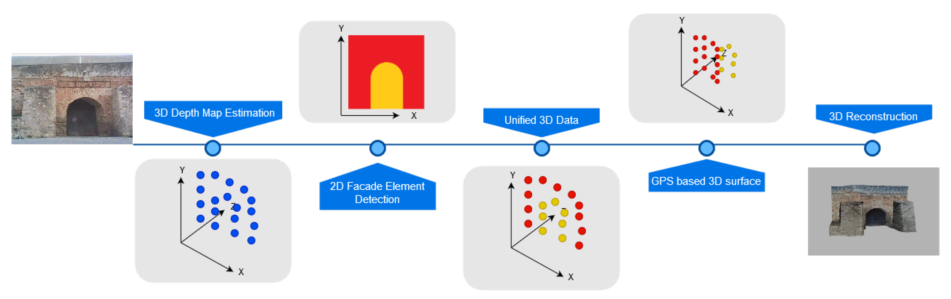
The proposed method refines the previous approach by tackling feature shape constraints, cost and automation concerns via utilizing detailed DNN based data and georeferenced information. The overall workflow is shown in Figure 2. FCRN-Depth produces a 3D depth point cloud which is fused with Pix2Pix feature detection data by one to one associations between the two sets. Georeferenced data further refine the cloud by iteratively correcting the spatial position of 3D points. A suitable surface reconstruction algorithm and texturing techniques produce the final realistic 3D façade model.
3. Experimental Results
This section presents the experimental results for each of the proposed methodological direction towards the refinement of our framework. In our experiments, we assess the performance of each method in well-known data sets and finally, in two case studies.
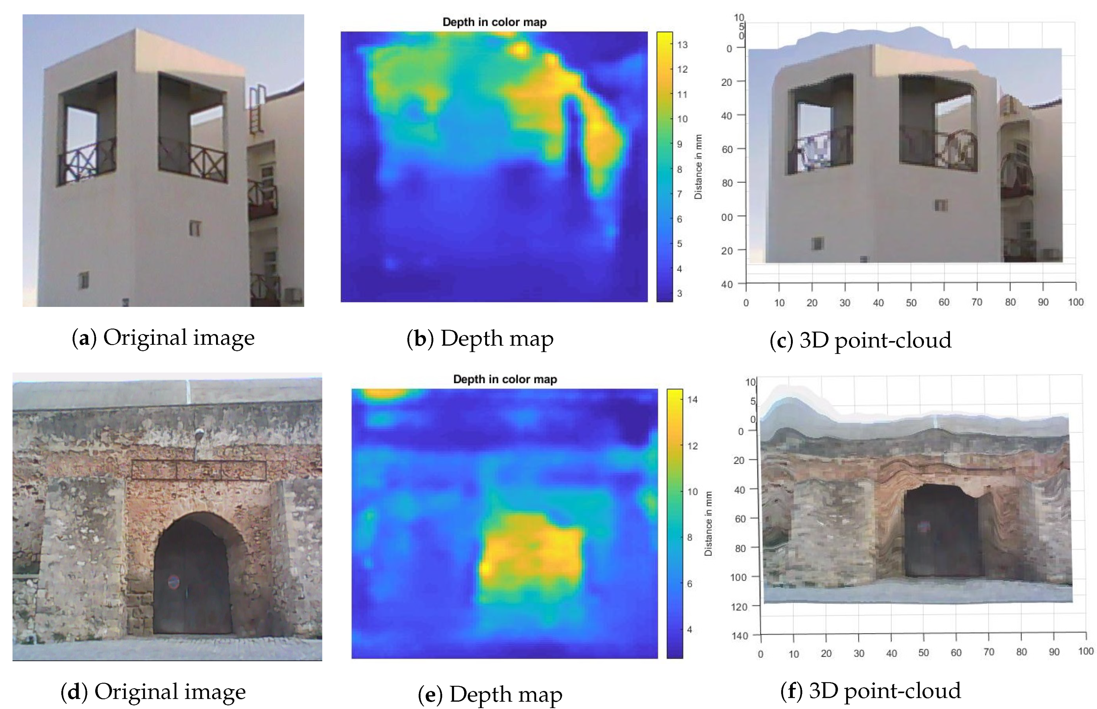
These case studies involve two building structures located at the city of Chania, in the province of Crete, Greece. The first building corresponds to a modern structure, located in the campus of the Technical University of Crete, which exhibits uniform façade color characteristics, and smooth surfaces, so called modern building in this study. Contrary the second case study refers to one of the famous Neoria buildings, a historic monument built during the Venetian occupation of Crete (around the 15th century), so called Neoria. This specific monument contains rock-textured wall façades, with irregular and coarse surfaces. Example images are illustrated in Figure 3a,d.
The final set of our experiments, involves the incorporation of the new methodologies in the overall framework, and the comparison, in terms of quality, of the final 3D building reconstruction to the reconstruction produced by our previous work [20].
3.1. DNN Training Specifications
Before proceeding with the presentation and commenting of the experimental results, we will first provide a brief overview of the changes and training specifications that were followed for the deep learning models mentioned in the previous section. Regarding the depth prediction, we used the pre-trained weights of FCRN-Depth [21], in the Make3D dataset [37]. This data set consists of outdoor scene images, a majority of whom are building façades, which made ideal the model for our case of study. Moreover, the depth data were selected with LiDAR systems allowing for dense depth map estimates to be produced by the model. Regarding the general aspects of the deep architecture, the input is RGB image data resized to 304 × 228 pixel resolution, and the output depth map resolution is 160 × 128. In order to produce one-to-one depth and façade element class correspondences we up-sampled using bi-linear interpolation the output to 256 × 256 pixels, similar to the output of Pix2Pix.
Concerning the façade segmentation and façade element detection, as previously stated, we retrain Pix2Pix to eTRIMS. Retraining was performed with batch size set to 4 samples per batch, and for 15K epochs, with data augmentation (rotation, shifting and zooming effects) and using the Adam optimizer with a 0.0002 learning rate.
3.2. Depth Map and Protrusion Estimation
This subsection presents the experimental results of applying FCRN-Depth to our case studies. Figure 3 depicts the depth map estimates using FCRN-Depth for the modern building and Neoria buildings as well as their respective point-clouds. We can observe that FCRN-Depth provides dense estimates with a relative structural-related consistency between the pixel-wise depth values.
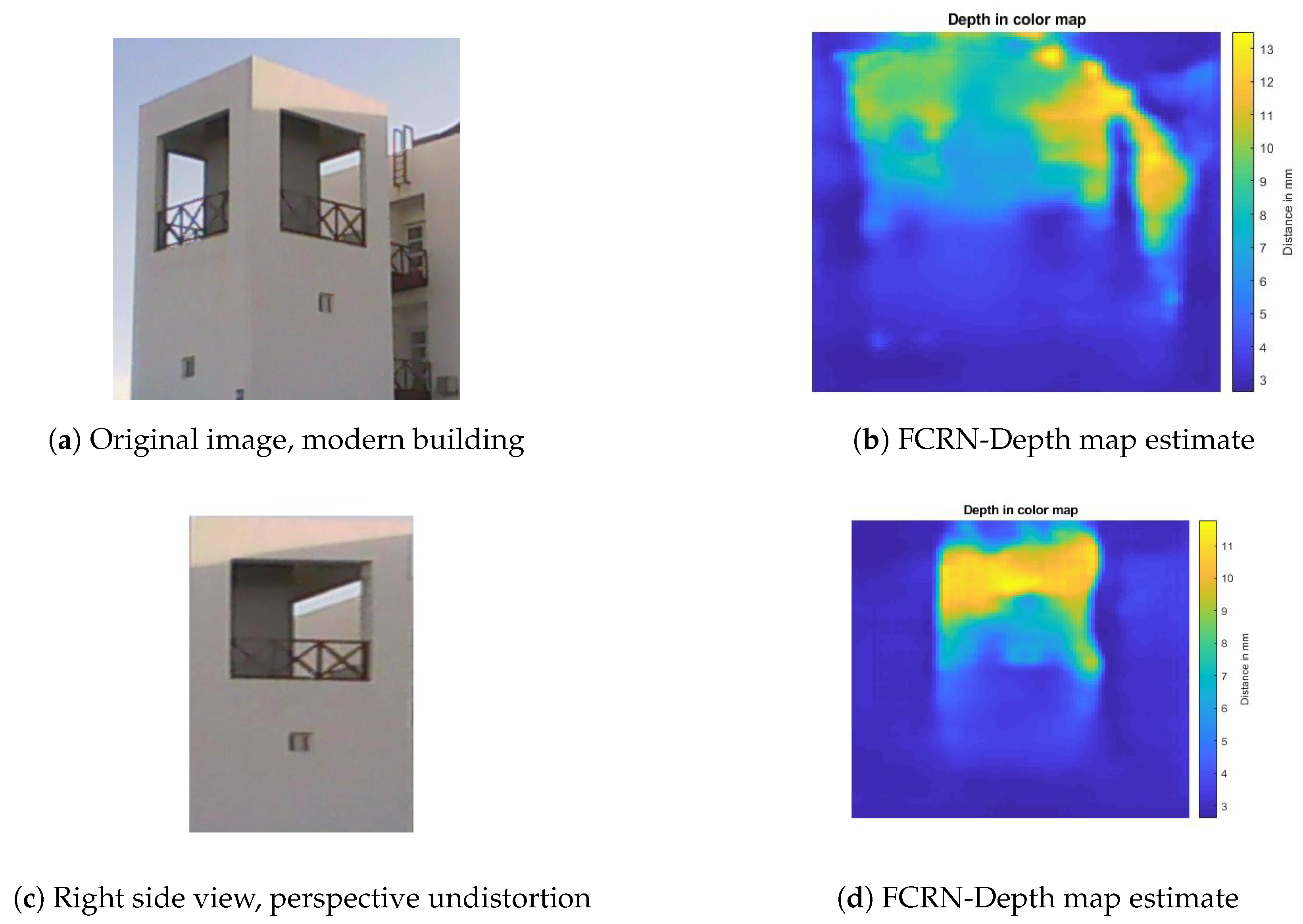
We can observe that for the case of the modern building the depth map estimate of FCRN-Depth is affected by the existence of perspective projection distortion, due to the oblique viewing angle as well as the size of the structure. This kind of distortion is common in cases of photos of large structures [38]. Our experiments indicate that removing this distortion and examining of isolated sides of the building appears to improve the depth map estimate of FCRN-Depth. This is highly justifiable since FCRN-Depth has been trained with building façade images of Make3D that depict front-facing unique sides. In order to correct the perspective distortion for a multi-view image of a building, we manually defined corner points for each specific view, and then cropped and wrapped the image based on the estimated geometric transformation computed using the control point pairs (manually selected corners and an ideal rectangle parallelogram) that alleviates the perspective distortion.
Figure 4 illustrates the FCRN-Depth map estimation improvement for the case of the modern building. We can observe that despite the obvious improvement in the depth prediction, depth estimates about previously ignored façade elements, such as for the case of the small window underneath the main window opening in the right side view of the building. Moreover, by reformulating the multi-view single image depth estimation problem into a side-specific depth estimation problem increases the overall depth estimation accuracy for façade elements.
Compared to the depth maps produced and utilized in our previous work, the estimates of FCRN-Depth are denser and cascade the structural coherency of pixels belonging to specific façade elements, into their depth values. These two factors will be presented in the subsequent paragraph lead to better protrusion estimates for the façade elements. However, the derived depth maps cannot at this point be used for initial crude 3D reconstructions as the depth value estimates are not very accurate and consistent especially in the areas of skeletal building components. This limitation is alleviated with the incorporation of the georeferenced data.
Façade element protrusion estimation: In our previous work, the protrusion attribute for each of the detected façade elements is derived based on the depth map generated by the stereoscopic image sensor rig. The protrusion of a façade element, such as a window, refers to the relative depth difference between the building wall and the façade element. This information is complementary to the 2D location of the façade elements, derived from the façade segmentation and element detection stage, and is incorporated to the final 3D model to provide a more realistic reconstruction. The depth difference is computed based on the mean depth value of the pixels belonging to the façade elements and the pixels belonging to building wall in a neighboring to the façade element region (threshold set to pixels) [14].
Based on the aforementioned exploitation of the depth map, in Table 1 we compare the accuracy of the relative depth difference estimate, computed using (a) the stereoscopic depth map estimate combined with a rectangular fitting for façade element detection, and (b) the depth map by FCRN-Depth combined with the façade element segmentation masks generated by Pix2Pix, as opposed to the ground-truth. Our experiments were applied only on the Neoria building case, since the modern building does not contain actual windows with finite protrusion.
We can observe that the protrusion estimates generated with the utilization of the depth map by the stereoscopic image sensor rig leads to an average 0.038 meters absolute average deviation from the ground-truth cases regarding the examined façade elements (windows), and a meters for the Neoria door case. Moreover, it is highly affected by perspective distortion affects, which is obvious in the increase of estimation deviations for the upper window cases. On the contrary, the deep learning-based approach leads to lower deviations which overall can lead to better protrusion incorporation scales into the 3D reconstructed model.
In conclusion, our experiments present the superiority of the deep learning-based approach compared to the stereoscopic-based depth estimation process in terms of estimation robustness, simplicity and relative estimation deviation compared to the ground-truth. These observations in accordance with the single camera sensor requirement, the camera calibration absence and the reduction of the amount of data acquisition process specifications and limitations, results in considering end-to-end deep learning-based SIDE methodologies, such as FCRN-Depth, as an excellent and promising choice on the way to developing an automated and relatively economical system.
3.3. Façade Element Detection
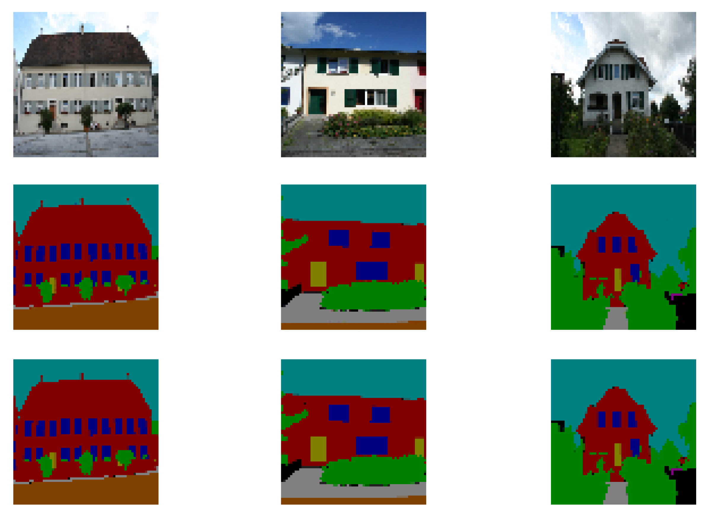
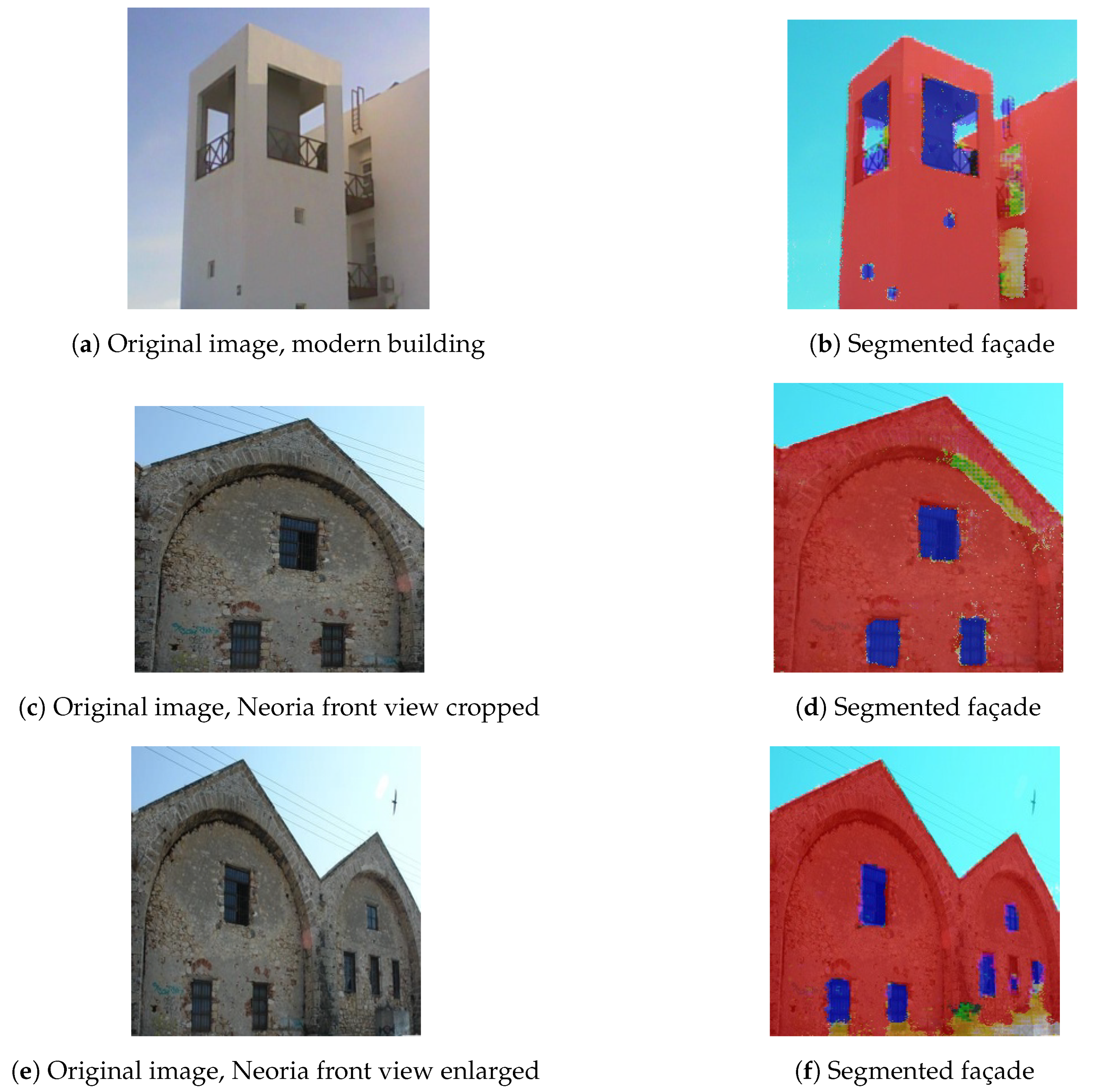
Regarding the façade element detection, as we retrained Pix2Pix in the eTRIMS Image Database, leading the network to produce façade segmentation images of 8 classes of which 3 of them correspond to building structural elements (building, window, door). For our 3D reconstruction we only retain these 3 classes. Figure 5 and Figure 6 illustrate original images and the corresponding façade segmentations produced by Pix2Pix. The first figure presents the estimates from the test image set of eTRIMS, for which we also provide the ground-truth segmentation. The second figure depicts the segmentation estimates for the building cases examined in our case of study.
Concerning the estimation error in the eTRIMS image dataset, Pix2Pix resulted in MSE score, leading to fairly accurate estimation. To evaluate the performance we followed a 90:10 split ratio. Figure 5 displays sample image cases from the test set of eTRIMS, for which as it can observed the segmentation performance is very close to the actual ground-truth. As for the in the wild images used in our case of study, we can observe that the generated segmentations are fairly accurate mapping of the original RGB images. In fact, we can observe that the model is able to produce accurate segmentations independent of the textures of façade elements. Additionally, this approach is more robust to affine transformations (shift, rotation) as well as zooming affects, compared to the approach that was used in our previous work. The performance of the rectangle fitting approach would be severely affected by zooming effects and view change, a problem that can be addressed on deep learning models through data augmentation.
Finally, since the SIDE method provides dense depth map estimates we can define one-to-one associations between the depth and façade element class for each pixel, which allows for 3D model development platform, such as Unity 3D, to be introduced with dense 3D point clouds, infused with pixel-wise class attributes.
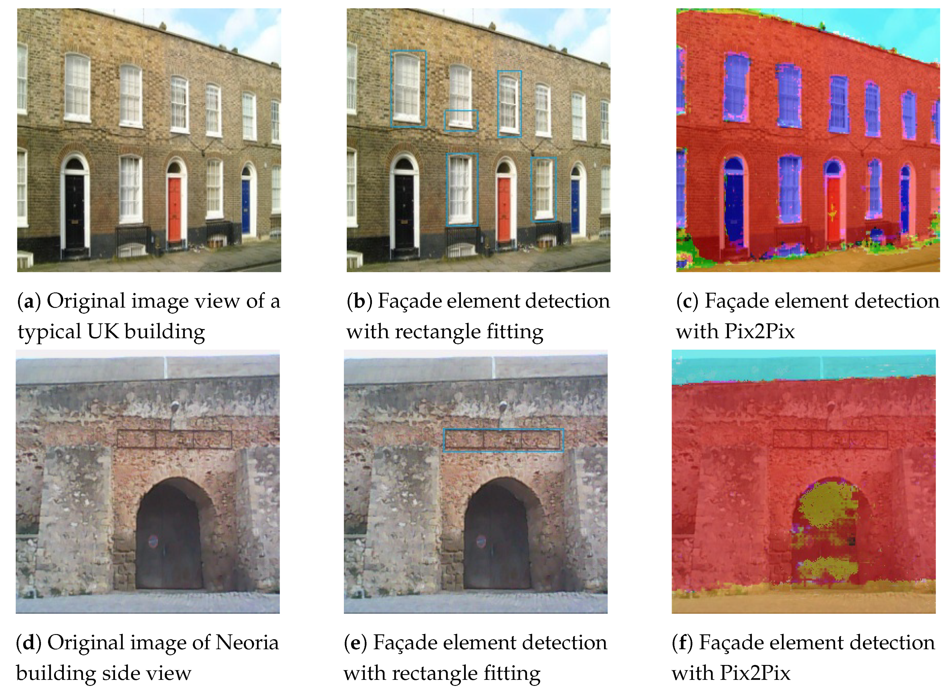
Pix2Pix façade versus Color-based segmentation and Rectangle fitting: At this point to further highlight the benefits from introducing Pix2Pix for the problem of façade segmentation, we proceed to a comparison to the methodology followed in our previous approach. The approach followed in our previous work, as stated earlier, is limited by the shape assumption and, thus it is bound to fail in cases of non-rectangular windows or doors. However, Pix2Pix does not contain any shape-related assumptions and thus, is not limited by such shape cases. Figure 7 illustrates the comparison between the two approaches for the Neoria side view building case and a typical rural house located in the United Kingdom (UK).
We can observe that the approach followed in our previous work failed to detect every window element for the UK house. This detection failure can be mainly attributed to the low performance of the active contour method preceding the rectangle fitting approach, and whose task is to generate candidate rectangle region proposals introduced to the rectangle fitting stage. Poor initialization and dense and complex textures highly affected the overall performance of this stage. Moreover, in our previous work there is no explicit discrimination between doors and windows (a solution can be to apply a color-based Support Vector Machine classifier to discriminate between the two classes). Both of them are considered the same façade element based only on the rectangle shape assumption. This fact beside the façade element discrimination limitations also limits the detection of doors with rectangular shapes leading to door cases such as the ones of the building cases of Figure 7, not being detected due to the arch shape of the door.
On the other hand, we can observe that Pix2Pix is able to detect with a relatively dense pixel-wise mask for each façade element, discriminating between the façade element classes, even for oblique view cases. However, in order to be useful in an automated 3D building façade reconstruction system, an instance segmentation stage must follow, to isolate each façade element instance. As mentioned, a simple blob detection approach for each façade element class is adequate for such task, and is a strategy that we follow in our current version of our framework.
3.4. Georeferenced 3D Façade Reconstruction
The depth related computed data and the façade element detection, as shown in the previous sections, are combined to aid the production of the feature enhanced reconstructed façade. The experimental results of the incorporation of the identified features in the semantic enriched point cloud, as well as the reconstruction of the final 3D mesh surface are presented in the following subsections.
3.4.1. Identification of the Pix2Pix Detected Elements in the Depth Point Cloud Data Set
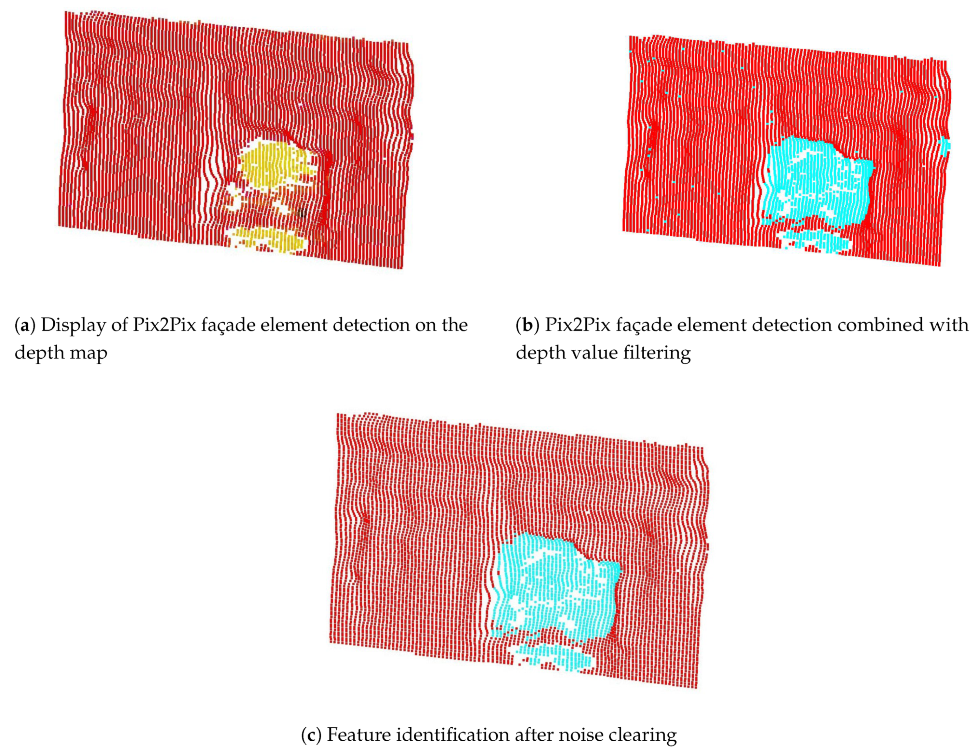
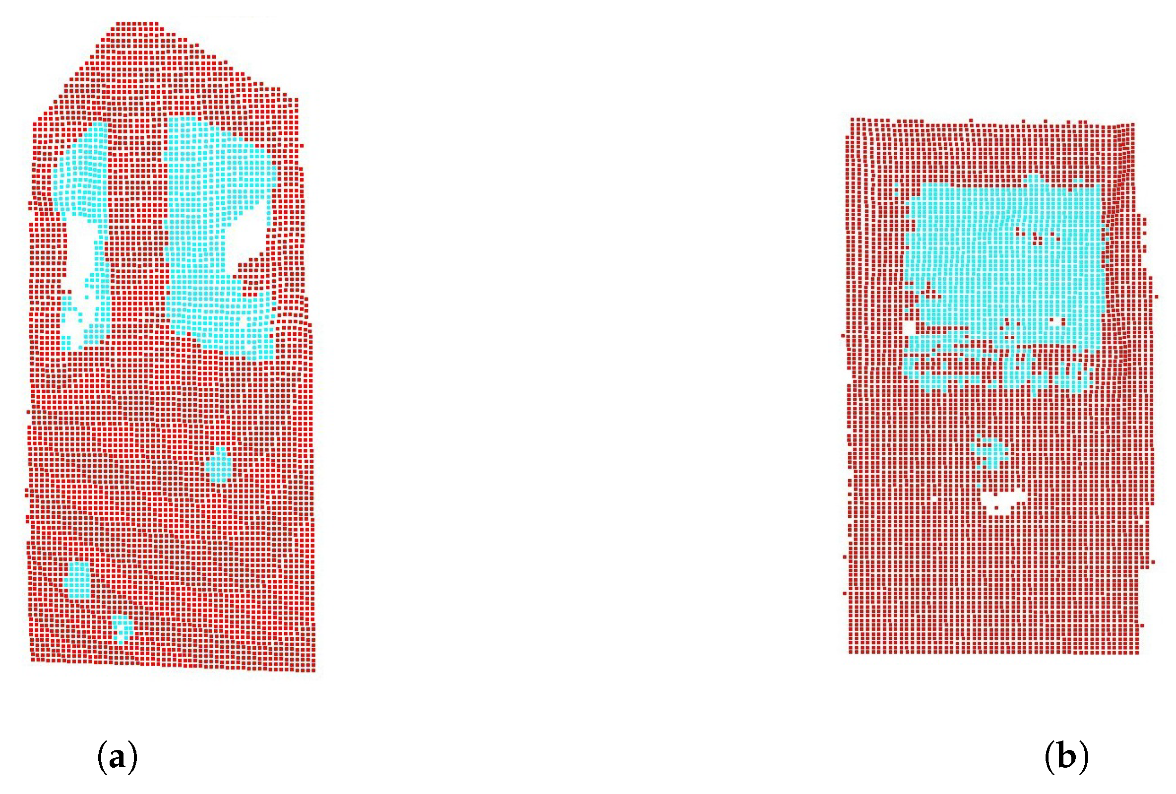
The inclusion of the detected feature elements in the 3D point cloud data set fulfills the purpose of the creation of a unified data set which will provide the basis for the façade reconstruction. By passing the color of the segmentation as an attribute to the depth point cloud, we are provided with the opportunity to perform a color based filtering and remove the classes that don’t belong to the building structure, e.g sky (blue) and road (orange). As mentioned previously, the union of the segmentation and depth value estimation results constitute the structural features. In that way depth map estimation data can compensate for plausible façade element detection discrepancies. However, by including in the data set areas with a specified depth limit, data noise is created in the form of small point batches in the cloud. In order to remove them, geometric queries were performed using alpha shapes. Alpha shapes groups neighbouring points in clusters, giving as the option to examine each one separately. At the Neoria building case study, we identified the largest one of those clusters as the door and removed the rest. There are gaps observed in the door area caused from the segmentation class filtering, which will later be filled during the triangulation process. An example of this feature identification method is shown in Figure 8. The inclusion of the depth estimation in the data establishes a more robust feature detection.
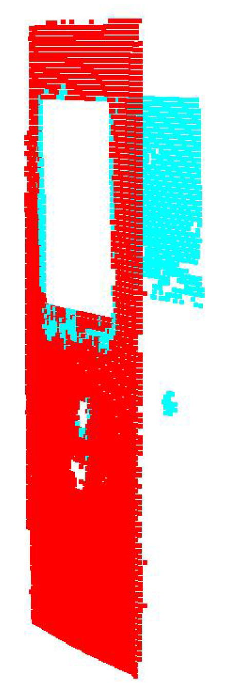
Regarding the modern building analysis, there was a modification of the approach. In that case study, the Pix2Pix segmentation estimates produce a relatively accurate mapping of the real features. On the other hand, the projection distortion in the analyzed images affects the depth map estimates. As it is demonstrated in Figure 4b and Figure 6b there is a heterogeneity in the outcome of the procedures, tampering with the aggregation of the data sets. However, due to the accuracy of the segmentation results, the depth map estimates are deemed redundant and a color based filtering on the cloud is considered sufficient for the feature identification. The results had only minor outliers which were filtered and removed (Figure 9).
3.4.2. Georeferenced Based Formulation of the 3D Façade Surface
The façade parts void of structural elements (doors, windows, etc.), that are beyond the range of the feature detection process contain semantic information as well, especially in cases of old buildings, such as the Neoria case study. The extraction of that information, is driven by the incorporation of georeferenced data in the workflow. The analysis of the 3D depth point cloud in accordance with the georeferenced data requires the registration of the two sets, transforming them in comparable entities under one homogeneous coordinate system. As indicated in our previous study, the 3D depth point cloud is registered with the georeferenced data via a spatial transformation driven by the Equation (4) in [20].
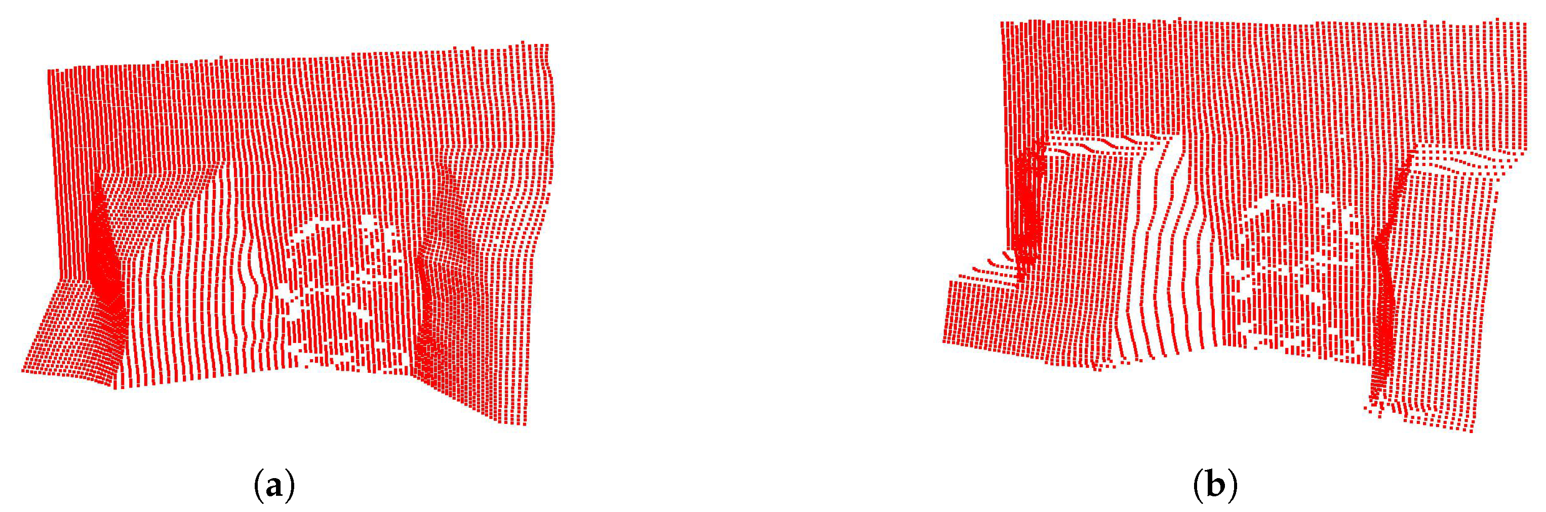
The newly georeferenced 3D depth point cloud is imported as input in the formerly explained iterative algorithm. The minimum signed distance of each point to the survey georeferenced data set is computed and its spatial position is recalculated according to it. Each iteration alters the morphology of the cloud by shifting the points accordingly in the 3D space, resulting in different 3D surface instances (Figure 10). The iteration stops when the highest calculated distance is the same as the previous iteration. It was observed that due to the value type, i.e., the GGRS87 coordinates have accuracy of 9 decimal points, the minute differences in the calculated distances prevent the algorithm from stopping. Thus, the termination condition is fulfilled with a tolerance of 0.5% of the max value between the highest distances in the last two operations. In Figure 10b the semantic enriched point cloud of the Neoria building is shown, where structural fidelity is achieved. The algorithm executed 12 iterations to match the termination condition.
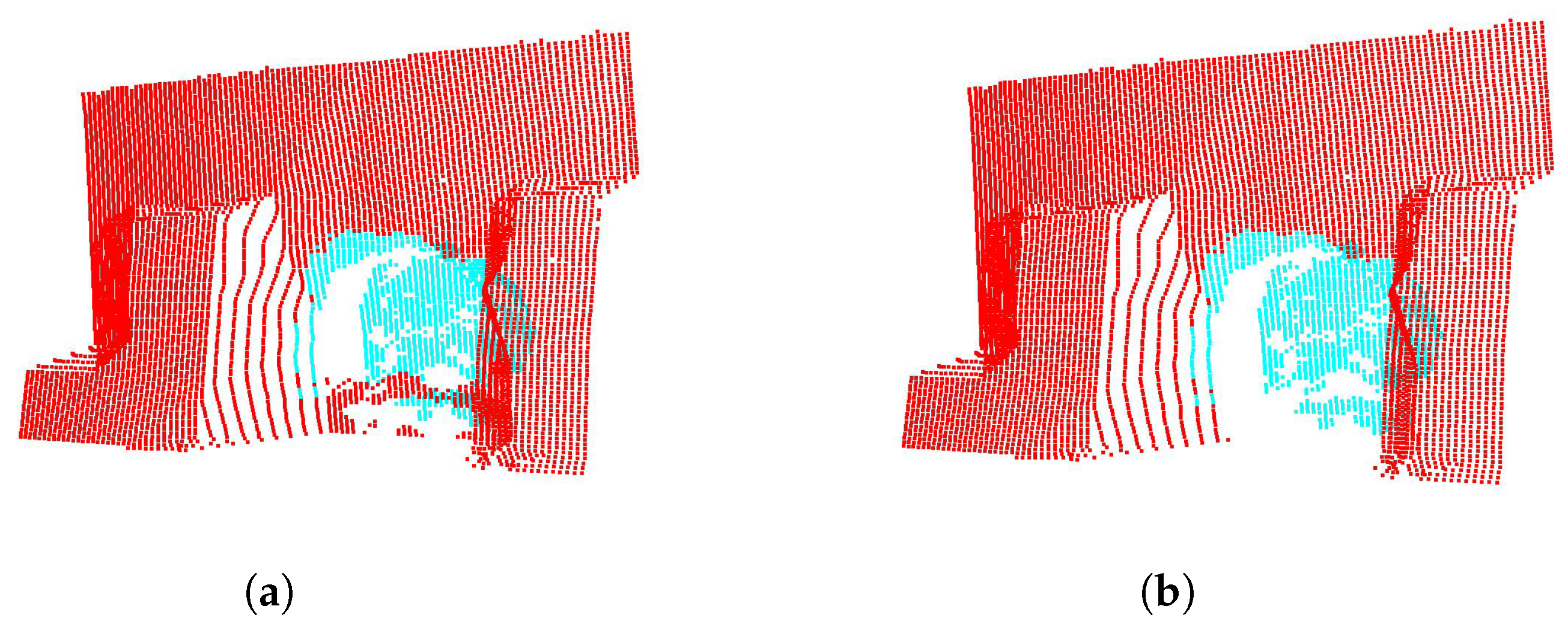
Next, the protrusion estimation is integrated in the cloud. The feature element information previously detected is passed in the cloud as color attribute, while establishing a region of interest. The refinement of the protruded area is achieved by figuring which survey georeferenced points are inside the region of interest, creating their outline and subsequently filtering out the feature element points that fall outside the georeferenced outlined area. The feature identification in Figure 8c drives the establishment of the georeferenced outline. More specifically, the blue cloud points that represent the feature identification are checked in order to determine if they reside in the georeferenced outlined region. The blue points included in the region are augmented with the protrusion estimation. Cloud points that lie inside the georeferenced outline but are not detected (i.e., not blue) are discarded. Figure 11 demonstrates the outcome of this process. The blue area that corresponds to the feature identification encloses the georeferenced points outlining the door. Only the blue points residing in the georeferenced formed region are protruded.
The distorted image data of the modern building case study, hinder the proper implementation of the suggested workflow. The perspective distortion of the image in Figure 4a which is passed in the 3D depth point cloud (Figure 9a), restraints the correct geographical mapping. This is due to the fact that while the input data represent two perpendicular sides of a building, the depth point cloud approximates in fact a planar surface. Another reason is that the parallelism and angles of the structural elements are not preserved due to the viewing position, prohibiting the correct assignment of the geographic coordinates on them. Bypassing these concerns and for the sake of argument, the cloud of Figure 9a was parsed as input to the iterative algorithm. The inaccurate mapping, as well as the inconsistency of the georeferenced points with the point cloud (large distance calculations), prohibited the process from terminating and fell in an eternal loop. The analysis of the distorted modern building case study was inconclusive.
The workflow focuses mainly on façades, i.e., front facing structures, thus the isolated and perspectively corrected side of the building (Figure 4c) provides us with the chance to examine the modern building case. The depth cloud of Figure 9b is parsed as input to the iterative algorithm. The notable aspect of that case, is that the algorithm operated as a rectification of the depth point cloud. Since we examine a modern building with smooth, flat exterior, the surveyed points of the façade coincide with a plane surface. The iterative process of shifting the points of the cloud according to the georeferenced data, conduce to the improvement of the initial depth estimation. Thus, surface areas with no structural elements and depth inconsistency, are refined. The algorithm terminated after 10 iterations. There are two identified features in that façade: the main wide window and the small one underneath. In order to proceed, we need to separate the two identifications, which is achieved with the utilization of the already mentioned alpha shapes. The alpha shape of the points representing the identified features (blue points), contains two regions. The distinction of these regions guide the protrusion refinement. The outline of the georeferenced points that reside in the regions, filter the cloud points to be protruded. Another noteworthy issue in this case is that both windows are hollowed. That means that the points shouldn’t be augmented with protrusion estimation but removed. However, the removal of the feature points will create gaps in the point cloud which will be filled during the triangulation process. To bypass this issue, it is decided to protrude the feature points with an arbitrary value instead of removing them (Figure 12), thus the triangulation process will fill plausible erroneous gaps created from the color based filtering of the identification procedure and retain the feature structure (Figure 13a). After the surface triangulation the mesh area belonging to the features is removed (Figure 13b).
Point cloud to mesh reconstruction: The morhologically enriched point cloud is subsequently parsed as input in a surface reconstruction algorithm. Having considered the Poisson surface reconstruction algorithm [39] as an alternative to the Delaunay triangulation [40], it was eventually dismissed as it is better suited for closed 3D surfaces with minimum sharpness. Delaunay retains the angles and is better suited for more planar surfaces [41], as is the case in this study. The deep learning based results of the current approach, combined with the iterative algorithm contributes to the materialization of a detailed data set which in turn results in a Delaunay triangulation with high geometric fidelity, requiring minimal post processing refinement (Figure 13 and Figure 14).
Texture mapping concludes the workflow by simulating the real surface. The two stage procedure (also implemented in [20]) involves diffuse mapping, which defines the façade’s main color through image sampling and normal mapping which gives the impression of realism by using the pixel RGB values of said image sampling to orient the surface normal. The normal is used during illumination calculations in Unity 3D enhancing the perception of surface details [42] (Figure 15 and Figure 16).
Current façade reconstruction workflow versus [20] approach: The advantages of the newly examined facade reconstruction process are evident through the comparison with the previous approach. The formulation of a unified data set impacts the fidelity of the final model by reducing dissimilar data merging and transformations between different coordinate systems. The FCRN-Depth produced 3D point clouds provided the initial data set upon which the examined methods were tested and presented. Feature identification was carried out and projected on the cloud which itself was filtered according to the segmentation classes and morphologically processed. The outcome was the creation of a single data set which contained depth, feature and protrusion information. In contrast, the previous approach began with 2D information which was mapped to 3D space with an augmented third coordinate and integrated spatial information through a created georeferenced infused interpolated surface. The data composing the surface’s semantic information were derived from a mixture of sources, the x, y dimensions from morphologically processed image data, while the z dimension was acquired from the georeferenced interpolated surface. The introduction of depth point cloud based process eliminated the need for the creation and use of the interpolated surface. To summarize, the previous approach generated georeferenced based information and fused it with image data, while the current deep learning methodology provided 3D data in its entirety, the spatial and geometric processing enhances the façade semantic information.
To quantify the comparison, we conducted a geometric evaluation of the semantic enhanced final façade [43]. To juxtapose the approaches we imitated the assessment used in the previous work, a comparison between the reconstructed 3D model and geometric raw data of the same type used in the methodology. The employment of this evaluation, not only can underline the effect the process has on the final spatial information but also emphasizes the deep learning based data quality. The amalgamation of different data origins can yield errors which can be carried throughout the workflow, whilst a unified data source minimizes the effect of external parameters. We compare the final 3D model with tacheometry measurements of the same type used in the workflow, which have considered the reference ground truth. The deviation of the two data sets illustrates the effectiveness of each method. Each point of the compared 3D model is assigned the distance to its nearest neighbor in the reference georeferenced raw data cloud. The deviation is visualized as a color scalar field on the façade surface.
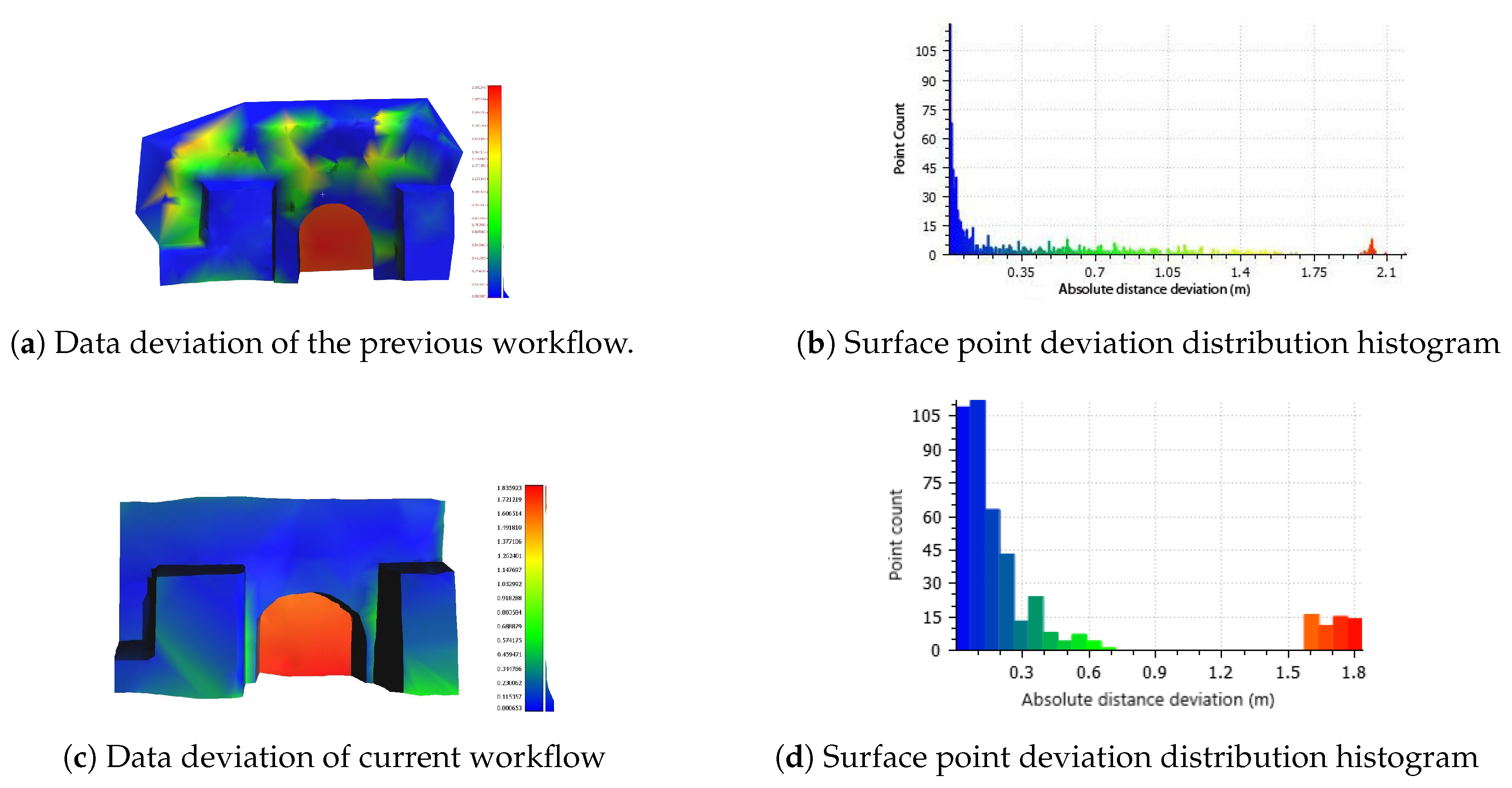
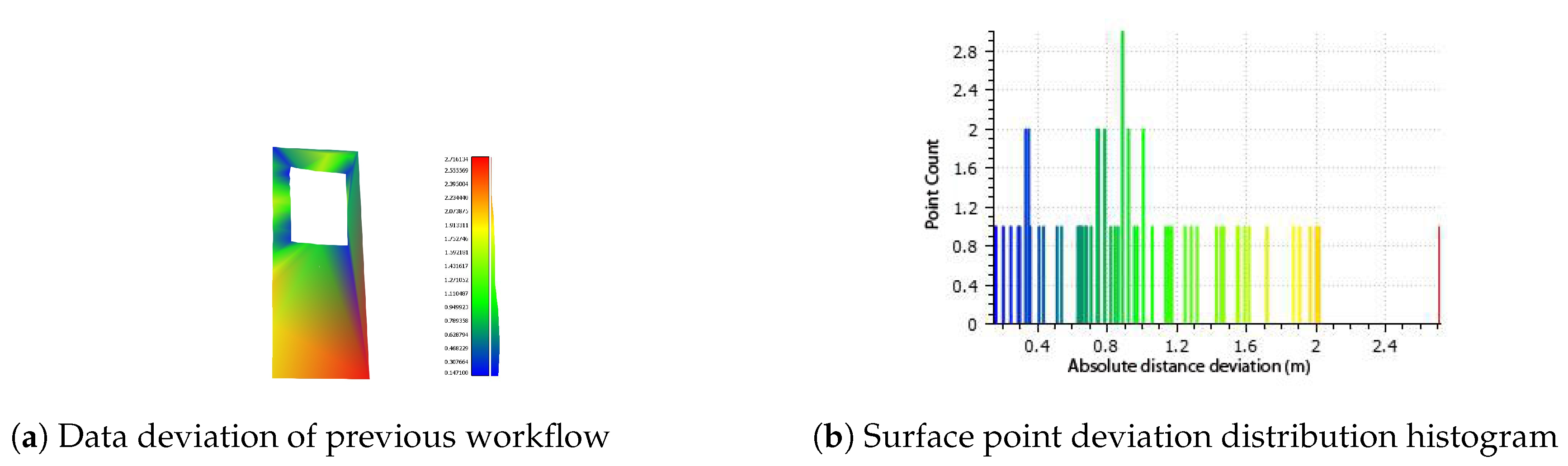
The assessment highlights the geometric fidelity achieved with the current approach. The employment of the depth point cloud as a basis unifying the morphological and spatial information under one coordinate system on a single dataset, erases the possible transformation errors of multiple data sources. The workflow performed on the Neoria building (Figure 17) upholds the structural fidelity across the surface and eliminates the deformations on plane areas where no georeferenced information is employed. Since the protrusion estimation of the door feature is not included in the geographical reference data, the observation of deviation on that area can be omitted from consideration. The accuracy of the feature is assessed in Table 1.
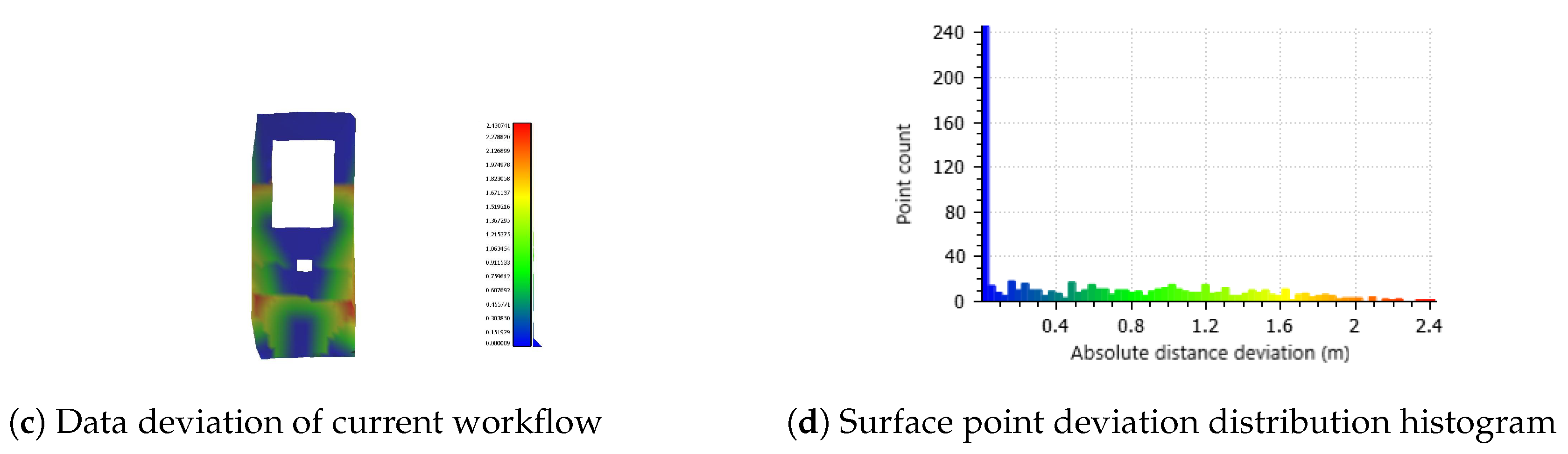
In Figure 18, the workflow outcome of the modern building case is geometrically assessed. Although the topology of the structure and the difficulties in acquiring proper image data (due to projection distortion) impact the results, there is an observable improvement. Areas with high deviations are minimized and the introduction of deep learning based element detection in the current process, makes possible the identification of minor features (small window), not previously inspected.
4. Conclusions and Future Work
This paper is presented as an extension of our previous approach [20], enhancing the robustness and limiting its constraints. The utilization of a deep learning based procedure expands the applicability range and fulfills the requirements in terms of data to be produced and exploited. The utilization of FCRN-Depth minimizes the input cost by eliminating the need for a stereoscopic camera rig, eliminates the depth estimation deviation from the ground truth and provides dense and relatively coherent data clouds, facilitating the mesh reconstruction.
The GAN-based segmentation procedure erases the notion of initial shape assumption and robustly detects structural elements independent of textural semantics, something that our previous work was prone to. The application of the Pix2Pix network increases the number of segmentation classes, refining the detection and making the discrimination between features possible. As a last stage, the 3D reconstruction is assisted by one-to-one association between depth and feature segmentation data, which adjusted with georeferenced data, enhance the final fidelity of the model.
Overall, the proposed workflow enhances the automation, economy and applicability of the previous system. However, future studies will aim to decrease the system dependence on georeferenced data, expanding the range of structural attributes acquired from image driven methodologies. The exclusion of the georeferenced data registration step from the system will completely diminish plausible discrepancies on the final data quality. The goal is to employ georeferenced data only in the form of ground control points as a closing step for the final façade georeference. In regards to the utilization of deep learning, the results of the present work, indicate the robustness, scalability, flexibility and applicability of these methods to the façade element detection and protrusion estimation tasks. Future work on these tasks will aim to further expand the number of façade element classes being identified as well as the detection accuracy, by (a) utilizing deeper and more complex DNN architectures, and, (b) exploiting and possibly combining various façade element segmentation data set. The goal is to expand the training sample pool, allowing the DNN architecture to gain access to a wider range of information.
Finally, future work will also focus on (a) expanding the case studies for which the proposed framework is tested, (b) utilize end user expertise feedback, and (c) include extensive quantitative and qualitative experimental results and comparisons between the proposed methodology and existing higher accuracy laser scanning results for a larger and more diverse building façade cases.
Author Contributions
Konstantinos Bacharidis introduced the conceptualization. Konstantinos Bacharidis and Froso Sarri wrote the software and wrote the original manuscript. Lemonia Ragia validated the results, reviewed and edited the manuscript. All authors have read and agreed to the published version of the manuscript.
Funding
This research received no external funding.
Acknowledgments
We would like to thank the authors of [21], for publicly releasing the code implementation of their model.
Conflicts of Interest
The authors declare no conflict of interest.
Abbreviations
The following abbreviations are used in this manuscript:
| DNN | Deep Neural Network |
| FCRN-Depth | Deeper Depth Prediction with Fully Convolutional Residual Networks |
| MSE | Mean Squared Error |
| SFM | Structure from Motion |
| SVMs | Support Vector Machines |
References
- Pu, S.; Vosselman, G. Building Facade Reconstruction by Fusing Terrestrial Laser Points and Images. Sensors 2009, 9, 4525–4542. [Google Scholar] [CrossRef] [Green Version]
- Abmayr, T.; Härtl, F.; Reinköster, M.; Fröhlich, C. Terrestrial Laser Scanning: Applications in Cultural Heritage Conservation and Civil Engineering. In Proceedings of the ISPRS Working Group V4, Mestre-Venice, Italy, 22–24 August 2005. [Google Scholar]
- Ma’arof, I.; Bahari, S.Z.; Latif, Z.A.; Sulaiman, N.A.; Samad, A.M. Image based modeling and documentation of Malaysian historical monuments using Digital Close-Range Photogrammetry (DCRP). In Proceedings of the 2013 IEEE International Conference on Control System, Computing and Engineering, Penang, Malaysia, 29 November–1 December 2013; pp. 424–429. [Google Scholar]
- Reinoso, J.F.; Moncayo, M.; Barrera, D. Close-range photogrammetry applied to the documentation of cultural heritage using telescopic and wide-angle lenses. Imaging Sci. J. 2014, 62, 387–394. [Google Scholar] [CrossRef]
- Tang, P.; Huber, D.; Akinci, B.; Lipman, R.; Lytle, A. Automatic reconstruction of as-built building information models from laser-scanned point clouds: A review of related techniques. Autom. Constr. 2010, 19, 829–843. [Google Scholar] [CrossRef]
- Becker, S.; Haala, N. Combined feature extraction for façade reconstruction. In Proceedings of the ISPRS Workshop Laser Scanning, Espoo, Finland, 12–14 September 2007; pp. 241–247. [Google Scholar]
- Kersten, T.; Mechelke, K.; Maziull, L. 3D model of al zubarah fortress in qatar - terrestrial laser scanning vs. dense image matching. ISPRS Int. Arch. Photogramm. Remote Sens. Spat. Inf. Sci. 2015, XL-5/W4, 1–8. [Google Scholar] [CrossRef] [Green Version]
- Dellaert, F.; Seitz, S.M.; Thorpe, C.E.; Thrun, S. Structure from motion without correspondence. In Proceedings of the IEEE Conference on Computer Vision and Pattern Recognition (CVPR 2000), Hilton Head Island, SC, USA, 15 June 2000; Volume 2, pp. 557–564. [Google Scholar]
- Luhmann, T.; Robson, S.; Kyle, S.; Boehm, J. Close-Range Photogrammetry and 3D Imaging; Walter de Gruyter: Berlin, Germany, 2013. [Google Scholar]
- Kersten, T.P. Virtual Reality Model of the Northern Sluice of the Ancient Dam in Marib/Yemen by Combination of Digital Photogrammetry and Terrestrial Laser Scanning for Archaeological Applications. Int. J. Archit. Comput. 2007, 5, 339–354. [Google Scholar] [CrossRef]
- Koska, B. The combination of laser scanning and structure from motion technology for creation of accurate exterior and interior orthophotos of St. Nicholas Baroque church. Int. Arch. Photogramm. Remote Sens. Spat. Inf. Sci. 2013, 40, 133–138. [Google Scholar] [CrossRef] [Green Version]
- Fritsch, D.; Becker, S.; Rothermel, M. Modeling facade structures using point clouds from dense image matching. In Proceedings of the Intl. Conf. on Advances in Civil, Structural and Mechanical Engineering, Hong Kong, China, 3–4 August 2013; pp. 57–64. [Google Scholar]
- Doulamis, A. Automatic 3D Reconstruction from Unstructured Videos Combining Video Summarization and Structure from Motion. Front. ICT 2018, 5, 29. [Google Scholar] [CrossRef]
- Paravolidakis, V.; Bacharidis, K.; Sarri, F.; Ragia, L.; Zervakis, M. Reduction of building façade model complexity using computer vision. In Proceedings of the 2016 IEEE International Conference on Imaging Systems and Techniques (IST), Chania, Greece, 4–6 October 2016; pp. 454–459. [Google Scholar]
- Neuhausen, M.; König, M. Automatic window detection in facade images. Autom. Constr. 2018, 96, 527–539. [Google Scholar] [CrossRef]
- Haugeard, J.E.; Philipp-Foliguet, S.; Precioso, F.; Lebrun, J. Extraction of Windows in Facade Using Kernel on Graph of Contours. In Image Analysis; Salberg, A.B., Hardeberg, J.Y., Jenssen, R., Eds.; Springer: Berlin/Heidelberg, Germany, 2009; pp. 646–656. [Google Scholar]
- Schmitz, M.; Mayer, H. A convolutional network for semantic facade segmentation and interpretation. ISPRS Int. Arch. Photogramm. Remote Sens. Spat. Inf. Sci. 2016, XLI-B3, 709–715. [Google Scholar] [CrossRef]
- Fathalla, R.; Vogiatzis, G. A deep learning pipeline for semantic facade segmentation. In Proceedings of the British Machine Vision Conference 2017 (BMVC), London, UK, 4–7 September 2017. [Google Scholar]
- Liu, H.; Zhang, J.; Zhu, J.; Hoi, S.C.H. DeepFacade: A Deep Learning Approach to Facade Parsing. In Proceedings of the Twenty-Sixth International Joint Conference on Artificial Intelligence (IJCAI-17), Melbourne, Australia, 19–25 August 2017; pp. 2301–2307. [Google Scholar] [CrossRef] [Green Version]
- Bacharidis, K.; Sarri, F.; Paravolidakis, V.; Ragia, L.; Zervakis, M. Fusing Georeferenced and Stereoscopic Image Data for 3D Building Façade Reconstruction. ISPRS Int. J. Geo-Inf. 2018, 7, 151. [Google Scholar] [CrossRef] [Green Version]
- Laina, I.; Rupprecht, C.; Belagiannis, V.; Tombari, F.; Navab, N. Deeper depth prediction with fully convolutional residual networks. In Proceedings of the IEEE 2016 Fourth International Conference on 3D Vision (3DV), Stanford, CA, USA, 25–28 October 2016; pp. 239–248. [Google Scholar]
- Ren, H.; El-khamy, M.; Lee, J. Deep Robust Single Image Depth Estimation Neural Network Using Scene Understanding. arXiv 2019, arXiv:1906.03279. [Google Scholar]
- He, K.; Zhang, X.; Ren, S.; Sun, J. Deep residual learning for image recognition. In Proceedings of the IEEE Conference on Computer Vision and Pattern Recognition, Las Vegas, NV, USA, 26 June–1 July 2016; pp. 770–778. [Google Scholar]
- Owen, A.B. A robust hybrid of lasso and ridge regression. Contemp. Math. 2007, 443, 59–72. [Google Scholar]
- Kass, M.; Witkin, A.; Terzopoulos, D. Snakes: Active contour models. Int. J. Comput. Vis. 1988, 1, 321–331. [Google Scholar] [CrossRef]
- Yu, F.; Koltun, V. Multi-Scale Context Aggregation by Dilated Convolutions. 2015. Available online: http://xxx.lanl.gov/abs/1511.07122 (accessed on 12 May 2020).
- Mathias, M.; Martinoviundefined, A.; Gool, L. ATLAS: A Three-Layered Approach to Facade Parsing. Int. J. Comput. Vis. 2016, 118, 22–48. [Google Scholar] [CrossRef] [Green Version]
- Isola, P.; Zhu, J.Y.; Zhou, T.; Efros, A.A. Image-to-Image Translation with Conditional Adversarial Networks. In Proceedings of the IEEE Conference on Computer Vision and Pattern Recognition, Honolulu, HI, USA, 21–26 July 2017; pp. 1125–1134. [Google Scholar]
- Korč, F.; Förstner, W. eTRIMS Image Database for Interpreting Images of Man-Made Scenes; Technical Report, TR-IGG-P-2009-01; University of Bonn: Bonn, Germany, 2009. [Google Scholar]
- Tyleček, R.; Šára, R. Spatial Pattern Templates for Recognition of Objects with Regular Structure. In German Conference on Pattern Recognition; Springer: Berlin/Heidelberg, Germnay, 2013. [Google Scholar]
- He, K.; Gkioxari, G.; Dollár, P.; Girshick, R. Mask r-cnn. In Proceedings of the IEEE International Conference on Computer Vision, Venice, Italy, 22–29 October 2017; pp. 2961–2969. [Google Scholar]
- Rusu, R.B.; Marton, Z.C.; Blodow, N.; Dolha, M.; Beetz, M. Towards 3D point cloud based object maps for household environments. Robot. Auton. Syst. 2008, 56, 927–941. [Google Scholar] [CrossRef]
- Gardiner, J.D.; Behnsen, J.; Brassey, C.A. Alpha shapes: Determining 3D shape complexity across morphologically diverse structures. BMC Evol. Biol. 2018, 18, 184. [Google Scholar] [CrossRef] [PubMed]
- Ragia, L.; Sarri, F.; Mania, K. 3D reconstruction and visualization of alternatives for restoration of historic buildings: A new approach. In Proceedings of the IEEE 2015 1st International Conference on Geographical Information Systems Theory, Applications and Management (GISTAM), Barcelona, Spain, 28–30 April 2015; pp. 1–9. [Google Scholar]
- Frisch, D. Distance Between Point and Triangulated Surface. 2016. Available online: https://www.mathworks.com/matlabcentral/fileexchange/52882-point2trimesh-distance-between-point-and-triangulated-surface (accessed on 3 March 2020).
- Muja, M.; Lowe, D.G. Fast approximate nearest neighbors with automatic algorithm configuration. VISAPP 2009, 2, 2. [Google Scholar]
- Saxena, A.; Sun, M.; Ng, A.Y. Make3d: Learning 3d scene structure from a single still image. IEEE Trans. Pattern Anal. Mach. Intell. 2008, 31, 824–840. [Google Scholar] [CrossRef] [PubMed] [Green Version]
- Hartley, R.; Zisserman, A. Multiple View Geometry in Computer Vision, 2nd ed.; Cambridge University Press: Cambridge, MA, USA, 2004. [Google Scholar] [CrossRef] [Green Version]
- Kazhdan, M.; Hoppe, H. Screened poisson surface reconstruction. ACM Trans. Graph. (ToG) 2013, 32, 1–13. [Google Scholar] [CrossRef] [Green Version]
- Edelsbrunner, H. Triangulations and meshes in computational geometry. Acta Numer. 2000, 9, 133–213. [Google Scholar] [CrossRef]
- Fabio, R. From point cloud to surface: The modeling and visualization problem. Int. Arch. Photogramm. Remote Sens. Spat. Inf. Sci. 2003, 34, W10. [Google Scholar]
- Ragia, L.; Sarri, F.; Mania, K. Precise photorealistic visualization for restoration of historic buildings based on tacheometry data. J. Geogr. Syst. 2018, 20, 115–137. [Google Scholar] [CrossRef]
- Lachat, E.; Landes, T.; Grussenmeyer, P. First experiences with the Trimble SX10 Scanning Total Station for building facade survey. Int. Arch. Photogramm. Remote Sens. Spat. Inf. Sci. 2017, 42, 405. [Google Scholar] [CrossRef] [Green Version]
Figure 1.
The pipeline of the proposed method in [20] for generating a realistic 3-D building model and façade reconstruction, by combining image and georeferenced point data.
Figure 1.
The pipeline of the proposed method in [20] for generating a realistic 3-D building model and façade reconstruction, by combining image and georeferenced point data.

Figure 2.
The updated pipeline of the current workflow for generating a 3D building model utilizing DNN based techniques and georeferenced data.
Figure 2.
The updated pipeline of the current workflow for generating a 3D building model utilizing DNN based techniques and georeferenced data.

Figure 3.
Depth map and corresponding 3D point-cloud for modern building and Neoria building side views. Depth maps were generated using the work of Laina et al. [21].
Figure 3.
Depth map and corresponding 3D point-cloud for modern building and Neoria building side views. Depth maps were generated using the work of Laina et al. [21].

Figure 4.
FCRN-Depth map estimation difference, by perspective projection distortion correction and side view isolation for the multi-view modern building image.
Figure 4.
FCRN-Depth map estimation difference, by perspective projection distortion correction and side view isolation for the multi-view modern building image.

Figure 5.
Sample images from the eTRIMS Image Database (first row), corresponding façade segmentations generated by Pix2Pix (second row), and, ground-truth façade segmentations (third row).
Figure 5.
Sample images from the eTRIMS Image Database (first row), corresponding façade segmentations generated by Pix2Pix (second row), and, ground-truth façade segmentations (third row).

Figure 6.
Façade segmentation estimates of Pix2Pix on the modern and Neoria buildings.

Figure 7.
Façade element detection comparison between the rectangle fitting approach in our previous work [20], and the Pix2Pix neural network. Comparison refers to window and door cases. In Pix2Pix dark blue indicates detected window regions, light yellow indicates door detections and green indicates vegetation. For rectangle fitting, bounding boxes indicate detected windows and doors without discriminating between the two classes. In this case the detection is heavily affected by the initialization of the active contour stage.

Figure 8.
Neoria building. In (a) the Pix2Pix façade element detection on the depth point cloud is displayed. (b) shows the detection combined with depth estimation data affected with outliers, and (c) displays the final feature identification after computational geometry clearing.
Figure 8.
Neoria building. In (a) the Pix2Pix façade element detection on the depth point cloud is displayed. (b) shows the detection combined with depth estimation data affected with outliers, and (c) displays the final feature identification after computational geometry clearing.

Figure 9.
Feature identification on the modern building. Identified features on the point cloud generated from (a) the original image, and, (b) from the isolated side.
Figure 9.
Feature identification on the modern building. Identified features on the point cloud generated from (a) the original image, and, (b) from the isolated side.

Figure 10.
Neoria building. Demonstration of the morphological difference of the generated point- cloud after (a) a single algorithm iteration, and, (b) the final semantic estimation after 12 iterations.
Figure 10.
Neoria building. Demonstration of the morphological difference of the generated point- cloud after (a) a single algorithm iteration, and, (b) the final semantic estimation after 12 iterations.

Figure 11.
Neoria building. The refined door feature displayed on the point cloud before (a), and, after (b) point removal.
Figure 11.
Neoria building. The refined door feature displayed on the point cloud before (a), and, after (b) point removal.

Figure 12.
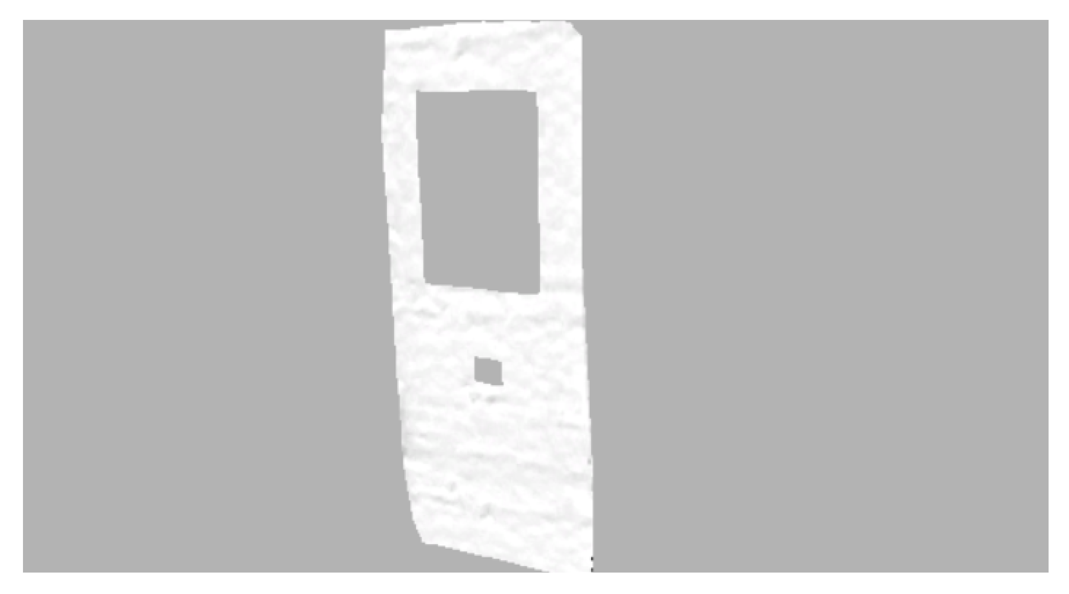
The feature enriched point cloud of the front facing single side of the modern building. The two features are identified and protruded instead of removed, in order to retain their structural form during triangulation.
Figure 12.
The feature enriched point cloud of the front facing single side of the modern building. The two features are identified and protruded instead of removed, in order to retain their structural form during triangulation.

Figure 13.
The 3D reconstructed surface of the modern building, (a) Triangulation with the arbitrary window protrusion, and, (b) Triangulation with windows removal.
Figure 13.
The 3D reconstructed surface of the modern building, (a) Triangulation with the arbitrary window protrusion, and, (b) Triangulation with windows removal.

Figure 14.
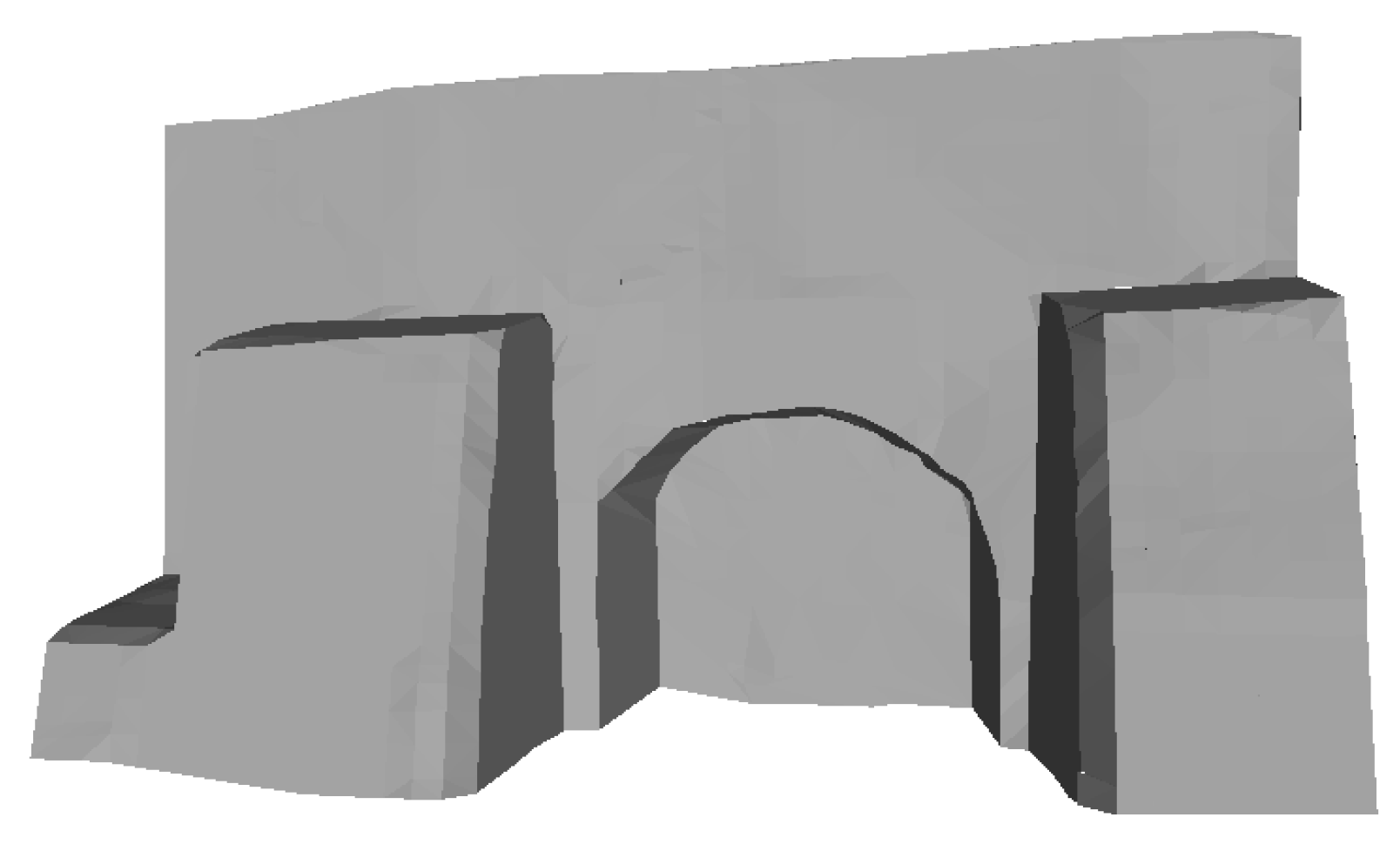
The 3D reconstructed surface of the Neoria building.

Figure 15.
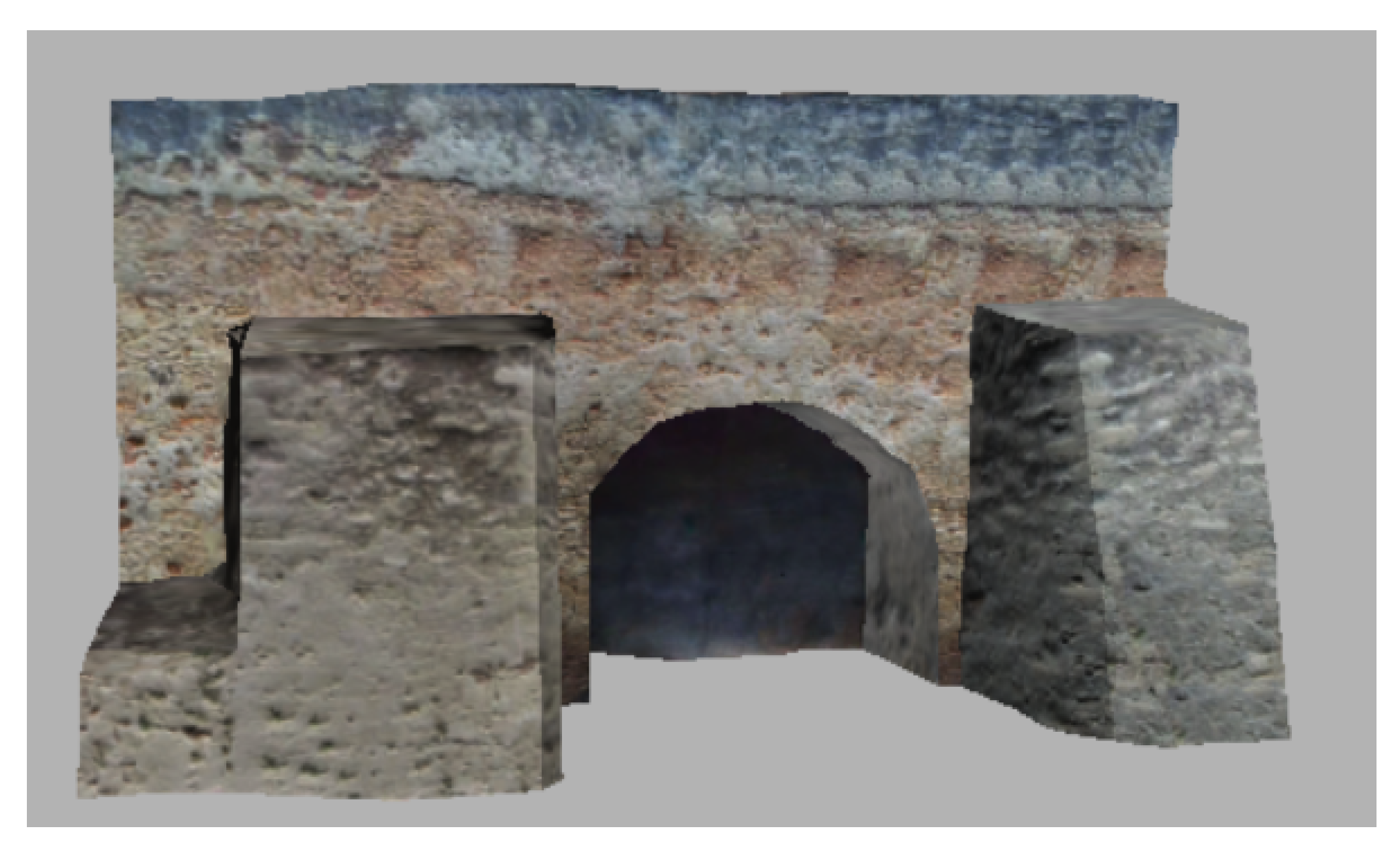
The final textured Neoria facade after diffuse and normal mapping.

Figure 16.
Th final textured modern building (front facing view) after diffuse and normal mapping.

Figure 17.
Visualization of the deviation of the Neoria building 3D model from the reference geographic data. The variation of the deviation values is illustrated with a color scalar field (blue < green < yellow < red). Histograms with the distribution of the deviation across each surface are also presented regarding the previous workflow (b), and the current workflow (d).

Figure 18.
Modern building deviation depiction. The variation of the deviation values is illustrated with a color scalar field (blue < green < yellow < red). Figure illustrates the corresponding histograms regarding the previous (b), and, the current workflow (d). Histograms demonstrate the improvement of the current workflow.


Table 1.
Protrusion estimate using (a) stereoscopic depth map, and (b) FCRN-Depth map, regarding the Neoria building.
Table 1.
Protrusion estimate using (a) stereoscopic depth map, and (b) FCRN-Depth map, regarding the Neoria building.
| Case Study | Stereoscopic Protrusion | FCRN-Depth Protrusion | Ground-Truth |
|---|---|---|---|
| Neoria front view (left bottom window ) | 0.544 (meters) | 0.540 (meters) | 0.520 (meters) |
| Neoria front view (right bottom window ) | 0.712 (meters) | 0.636 (meters) | 0.580 (meters) |
| Neoria front view (middle up window ) | 0.894 (meters) | 0.718 (meters) | Unavailable |
| Neoria side view (door) | 2.412 (meters) | 1.831 (meters) | 1.750 (meters) |
© 2020 by the authors. Licensee MDPI, Basel, Switzerland. This article is an open access article distributed under the terms and conditions of the Creative Commons Attribution (CC BY) license (http://creativecommons.org/licenses/by/4.0/).
Share and Cite
MDPI and ACS Style
Bacharidis, K.; Sarri, F.; Ragia, L. 3D Building Façade Reconstruction Using Deep Learning. ISPRS Int. J. Geo-Inf. 2020, 9, 322. https://doi.org/10.3390/ijgi9050322
AMA Style
Bacharidis K, Sarri F, Ragia L. 3D Building Façade Reconstruction Using Deep Learning. ISPRS International Journal of Geo-Information. 2020; 9(5):322. https://doi.org/10.3390/ijgi9050322
Chicago/Turabian StyleBacharidis, Konstantinos, Froso Sarri, and Lemonia Ragia. 2020. "3D Building Façade Reconstruction Using Deep Learning" ISPRS International Journal of Geo-Information 9, no. 5: 322. https://doi.org/10.3390/ijgi9050322
Note that from the first issue of 2016, this journal uses article numbers instead of page numbers. See further details here.