

Abstract
Here, we demonstrate a two-step electrochemical approach for the synthesis of cobalt chalcogenides, CoQ (Q = S or Se) based on the prior modification of a substrate with S or Se, followed by electrochemical reduction in a Co2+-complexing electrolyte to afford CoS or CoSe in film form. The two-step strategy circumvents a common problem with the electrodeposition of metal chalcogenides, namely admixture of the target material with undesired phases such as excess metal or the chalcogen. The strategy was combined with complexation to shift the free metal deposition regime to more negative potentials. Compositional analysis showed that as-synthesized films retain a stoichiometric ratio of Co and S or Se and XPS analysis confirmed the formation of CoS and CoSe. The electrodeposited films were successfully used as electrocatalysts for the triiodide/iodide redox system and showed comparable (or even, superior) performance to a Pt electrode. As also demonstrated both by the present work and by companion studies in our laboratories, the two-step strategy is generally applicable to a variety of other metal chalcogenides.
Export citation and abstract BibTeX RIS

This is an open access article distributed under the terms of the Creative Commons Attribution 4.0 License (CC BY, http://creativecommons.org/licenses/by/4.0/), which permits unrestricted reuse of the work in any medium, provided the original work is properly cited.
Transition metal chalcogenides, comprised of earth-abundant elements, are of both fundamental and practical interest.1 Especially, cobalt chalcogenides (CoQ, where Q is a chalcogen element) have attracted much attention for solar energy conversion applications because of their favorable attributes of good electrical conductivity, optimal band gap (∼1.5 eV) in terms of match with the solar spectrum, and a high optical absorption coefficient. Thus, they have been used as counterelectrodes in photoelectrochemical cells and in dye- or quantum dot-sensitized solar cells,2–4 and as a visible-light absorber in photovoltaic solar cells.5 They have also been deployed as an anode material in lithium-ion batteries,6 as a co-catalyst for water photooxidation,7 and as a glucose sensor.8
Recent interest has focused on their use as electrocatalysts for the hydrogen evolution reaction (HER) and the oxygen evolution reaction (OER).9–11 Interestingly, and illustrating the symmetry of catalysis mechanisms, the disulfide compound, CoS2 has also been studied for its efficacy in driving the oxygen reduction reaction (ORR). In these studies, CoQ (or CoQ2) served as effective alternatives for expensive, noble metal (e.g., Pt) catalysts that continue to be an economic roadblock for the practical realization of polymer electrolyte membrane fuel cells.
Cobalt selenides have been synthesized by several routes including chemical bath deposition,12 solvo- or hydrothermal method,4,13 mechanical alloying,14 and electrodeposition.2,3,5,9,15–19 Of these variant synthetic options, electrodeposition offers many advantages20 such as short synthesis time, simplicity, easy scale-up, the use of relatively mild conditions, and the fact that (volatile) organometallic chemicals are not needed (as in techniques such as molecular beam epitaxy and atomic layer deposition). In addition, the composition and structure of electrodeposited films can be controlled by controlling pH, electrolyte composition, or deposition potential.
Cathodic electrodeposition of compound semiconductor films generally begins with the co-deposition of component elements from their precursor species in dissolved form.20 However, one problem with this approach is co-deposition of undesired phases (free Co or free chalcogen) with the target materials (CoS or CoSe), resulting in negative effects on electrocatalytic activity and film stability.17,18 To overcome the contamination problem, previous authors developed a potential reversal technique for the synthesis of CoS.21 In their work, CoS was electrodeposited during the cathodic bias regime and the undesirable Co metal phase was removed during a subsequent anodic bias reversal.21 This technique was also applied for the synthesis of NiS to remove the metallic Ni co-deposited during the cathodic process.22 Other authors have used a hydrothermal treatment to remove Co(OH)2 and Co metal co-deposited with CoS during potentiodynamic electrodeposition.23
In this study, we employed a two-step approach for the electrosynthesis of CoS and CoSe films on polycrystalline Pt electrodes. In the first step, the Pt surface was pre-modified with S or Se, followed by electroreduction to S2− or Se2− in Co2+-containing electrolytes in the second step, to result in CoS or CoSe films. This two-step approach has been utilized in our laboratories for the electrosynthesis of a variety of metal chalcogenides and metal oxides, including ternary compounds.24 In the present study, we build upon our companion studies on CoSe17,18 and demonstrate the electrosynthesis of stochiometric films of CoS or CoSe without the need for any post-deposition treatment to remove unwanted phases. As in our companion studies,17,18 the simultaneous use of voltammetry and electrochemical quartz crystal microgravimetry (EQCM) is shown to be effective in unravelling the various mechanistic steps in the overall film deposition sequence.
Experimental
All chemicals were from Sigma-Aldrich and used without further purification. For voltammetry and EQCM, an EG&G Princeton Applied Research 263A instrument equipped with Power Suite electrochemistry software, a Seiko EG&G model QCA 922 instrument and an oscillator module (QCA 922-10), was used. A single compartment, three-electrode cell setup was used for electrochemical experiments at room temperature and comprised of an AT-cut, Pt-coated quartz crystal (geometric area, 0.2 cm2) working electrode, a Pt counterelectrode, and a Ag/AgCl/3 M NaCl reference electrode. All potentials below are quoted with respect to this reference electrode. For voltammetry, the potential scan rate was 20 mV s−1. The cleanliness of the Pt working electrode surface was checked by cyclic voltammetry in 0.5 M H2SO4 by cycling potential between 0.8 V and −0.6 V until the voltammetric and EQCM frequency signals were stable. The electrolytes were degassed with high-purity nitrogen prior to the electrochemical measurements and nitrogen blanket was used during the measurements.
Film morphology and composition were obtained on a field emission scanning electron microscope (JEOL Model JSM-7601F) equipped with an energy-dispersive X-ray emission analysis (EDX) probe. X-ray photoelectron spectra were obtained using a Thermo Scientific X-ray photoelectron spectrometer with a monochromatic Al Kα X-ray source.
Results and Discussion
The two-step approach for the electrosynthesis can be successfully employed for the synthesis of CoS only when pre-deposited S film is reduced before any reduction of Co2+ ions occurs.25 To examine this, a linear sweep voltammogram (LSV) combined with EQCM frequency changes, was first obtained for the Pt electrode in 0.1 M Na2SO4 containing 0.15 M CoCl2. As shown in Fig. 1A, deposition of cobalt started at −0.75 V, evident from the EQCM frequency decrease (mass increase) accompanying the cathodic wave. The peak at −1.10 V was assigned to the reduction of Co2+ ions to Co.17,26 A sulfur film, which was pre-electrodeposited at +0.6 V for 300 s in 0.1 M Na2SO4 containing 20 mM Na2S, was reduced below ∼−0.70 V in the 0.1 M Na2SO4 blank electrolyte (Fig. 1B). The pre-deposited S film was almost completely stripped, as deduced from the comparison of frequency changes of Pt electrode before deposition and after stripping. The cathodic peak at −0.80 V was assigned to the reduction of S0 to S2−. The data in Figs. 1A and 1B thus demonstrated that a two-step approach could indeed be applied to the electrosynthesis of CoS thin films because Co2+ ions were reduced at more negative potentials than S film stripping.
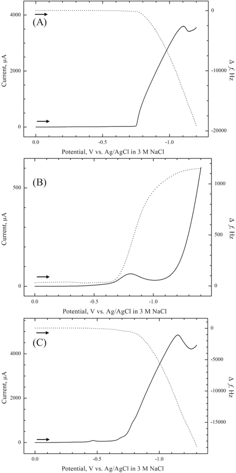
Figure 1. Combined cathodic linear sweep voltammetric (LSV) (——) and EQCM (- - - - -) scans for (A) a bare Pt electrode in 0.1 M Na2SO4 containing 0.15 M CoCl2, (B) a S-modified Pt electrode in 0.1 M Na2SO4 blank electrolyte and (C) a S-modified Pt electrode in 0.1 M Na2SO4 containing 0.15 M CoCl2. The S-modified electrode was prepared at the potential of +0.6 V in 0.1 M Na2SO4 containing 20 mM Na2S. Potential scan rate: 20 m V s−1.
Download figure:
Standard image High-resolution imageFigure 1C shows a linear sweep voltammogram simultaneously with EQCM frequency changes for a S-modified Pt electrode in 0.1 M Na2SO4 containing 0.15 M CoCl2. The sulfur film was pre-electrodeposited on Pt at +0.6 V in 0.1 M Na2SO4 containing 20 mM Na2S. Unlike in Fig. 1B, reduction of S to S2− ions resulted in a frequency decrease and mass uptake. Thus, the reaction of electrogenerated S2− with Co2+ in electrolyte resulted in CoS films being formed in situ on the Pt substrate. It is worth noting that the solubility product of CoS is very low, 5 × 10−23,27 attesting to the fact that the precipitation reaction is favored. The very small cathodic peak at ∼−0.46 V is assigned to the underpotential deposition of Co on the S-modified electrode surface.
Based on the data in Fig. 1, CoS films were potentiostatically synthesized using a S-modified Pt electrode at −0.7 V in 0.1 M Na2SO4 containing 0.15 M CoCl2. A deposition potential of −0.7 V was selected based on the data in Fig. 1 since the potential was negative enough for S reduction, but insufficiently low for cobalt deposition to be triggered. However, rather surprisingly, EDX analyses of electrodeposited films at −0.7 V showed cobalt sulfide films with an atomic ratio of 2:1 with excess metallic Co content. This is attributed to the induced co-deposition of metal ion on S or CoS surface, which is well known for metal chalcogenides (e.g., CdSe, CdTe and CoSe).18,28 This underpotential deposition of Co will result in CoS films with excess metallic Co.26 This problem can be solved by employing complexing agents such nitrilotriacetic acid (NTA) to form a Co2+-NTA complex, which can shift the reduction potential of cobalt ions to more negative potentials.26
Figure 2A demonstrates the effect of NTA on the potential for Co deposition on the Pt substrate. Compared to Fig. 1A, where cobalt deposition started at ∼−0.75 V, cobalt reduction began at ∼−1.1 V instead in a 0.1 M Na2SO4 electrolyte containing 0.15 M CoCl2 and 0.2 M NTA, the complexation shifting the deposition threshold by more than ∼350 mV. Thus, the frequency decrease (mass increase) below −1.1 V can be attributed to the cobalt deposition:26


Figure 2. Combined cathodic linear sweep voltammetric (LSV) (——) and EQCM (- - - - -) scans for (A) a Pt bare electrode and (B) a S-modified Pt electrode in 0.1 M Na2SO4 electrolyte containing 0.15 M CoCl2 and 0.2 M NTA. The S-modified electrode was prepared by the same procedure described in Fig. 1. Other details as in Fig. 1.
Download figure:
Standard image High-resolution imageNow, a two-step approach was employed again for the synthesis of CoS films using on the S-modified Pt electrode in 0.1 M Na2SO4 electrolyte containing both 0.15 M CoCl2 and 0.2 M NTA. As shown in Fig. 2B, S stripping started at ∼−0.70 V (same as in Fig. 1B) and the electrogenerated S2− ions reacted with cobalt species to produce CoS films on the Pt substrate. The frequency decrease in Fig. 2B with cathodic current due to S reduction starting at ∼−0.70 V was diagnostic of CoS film formation. The peak at ∼−1.2 V in Fig. 2B was due to bulk deposition of cobalt, in good agreement with Fig. 2A. Interestingly, a small peak at ∼−1.05 V was observed in Fig. 2B. Compared to Fig. 1A, it could be attributed to the reduction of uncomplexed, free Co2+ ions to Co.26
For the synthesis of CoS films, pre-deposited S layers were potentiostatically electroreduced at −0.85 V in 0.1 M Na2SO4 electrolyte containing 0.15 M CoCl2 and 0.2 M NTA until the EQCM frequency was stabilized, indicating complete stripping of the sulfur film. EDX analyses of the as-synthesized films afforded an elemental stoichiometric ratio of 1:1 (Co:S = 48.8%:51.2%). Figures 3A and 3B displayed the EDX elemental mapping images for Co and S, respectively, demonstrating uniform distribution of the elements on the film surface.
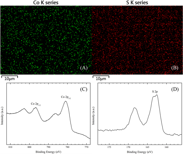
Figure 3. Elemental mapping by EDX of Co (A) and S (B), and high-resolution X-ray photoelectron spectra in (C) Co 2p and (D) S 2p binding energy regimes for an electrosynthesized CoS film.
Download figure:
Standard image High-resolution imageFurther evidence of the surface composition of the as synthesized CoS films was obtained from XPS as shown in Figs. 3C and 3D. For the Co 2p spectrum (Fig. 3C), binding energies at 796.6 and 781.1 eV could be assigned to 2p1/2 and 2p3/2, respectively, consistent with a Co2+ oxidation state.10 Another two peaks at 802.7 eV and 786.2 eV were attributed to the 2p53d7 (ground state of Co2+) and 2p53d8L, which exhibits a charge transfer from the ligand p-band to metal d-band.10,11 For the S region (Fig. 3D), a peak at 162.6 eV could be assigned to 2p, indicating the valence state of S to be −2.10,11 Another peak centered at 168.3 eV could be assigned to SO42−, probably originating from adsorbed electrolyte species. Note that bulk cobalt sulfate formation can be neglected owing to the high solubility of this compound.29
The two-step approach could be extended to another Co-chalcogenide, CoSe. A linear sweep voltammogram was obtained using a Se-modified electrode in a 0.1 M Na2SO4 blank electrolyte to examine whether a two-step approach could be applied to the formation of CoSe films (Fig. 4A). The Se film was pre-deposited on the Pt substrate at −0.60 V for 300 s in 0.1 M Na2SO4 containing 20 mM SeO2. Again, a cathodic wave centered at ∼−0.73 V was attributed to the reduction of Se to Se2− and the EQCM frequency increase (mass decrease) up to that of a bare substrate after a cathodic scan clearly indicated complete stripping of the Se layer.

Figure 4. Combined cathodic LSV (——) and EQCM (- - - - -) scans for (A) Se-modified Pt-coated quartz electrode in a 0.1 M Na2SO4 blank electrolyte and (B) Se-modified electrode in 0.1 M Na2SO4 electrolyte containing 0.15 M CoCl2 with 0.2 M NTA. The Se-modified electrode was prepared at the potential of −0.6 V in 0.1 M Na2SO4 containing 20 mM SeO2. Potential scan rate: 20 m V s−1.
Download figure:
Standard image High-resolution imageFigure 4B shows a voltammogram along with EQCM frequency change for a Se-modified electrode in a 0.1 M Na2SO4 electrolyte containing 0.15 M CoCl2 and 0.2 M NTA. Again, a cathodic wave with mass increase starting at ∼−0.70 V was assigned to the reduction of selenium to Se2− and formation of CoSe by reaction of Se2− with Co2+ in solution. Two cathodic peaks were seen due to cobalt deposition, as explained in Fig. 2B. The trends in frequency changes and currents due to Se reduction and subsequent reaction with cobalt species were very similar to those in Fig. 2B, although frequency changes were less pronounced here.
Compositional analyses of the as-deposited films resulted in CoSe with an atomic ratio of 1:1 (50.2%:49.8%) and EDX elemental mapping images demonstrated again uniform distribution of Co and Se on the Pt surface (Figs. 5A and 5B). The surface composition of the films was obtained from XPS analyses of as-deposited CoSe films. For the Se region (Fig. 5D), a peak centered at 54.5 eV was assigned to Se 3d5/2, consistent with the existence of Se2−.2,3,30 Another peak at 59.7 eV could be attributed to Se 3d3/2 in SeO2 resulting from surface oxidation.30,31 The high-resolution XPS peaks observed in Fig. 5C from cobalt were in agreement with corresponding results in Fig. 3C.
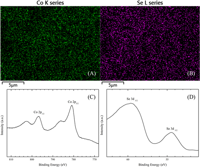
Figure 5. Elemental mapping by EDX of (A) Co and (B) Se, and high-resolution X-ray photoelectron spectra of (C) Co 2p and (D) Se 3d binding energy regimes for as-deposited CoSe sample.
Download figure:
Standard image High-resolution imageThe data above demonstrate that the two-step electrodeposition sequence can be combined with metal complexation to secure the electrosynthesis of stoichiometric CoQ (Q = S or Se) without the need for any post-deposition steps. Next, the use of these films in a practical application context, is presented. For this purpose, a redox probe, namely iodide/triiodide, was selected. This redox couple is commonly used as a shuttle in dye-sensitized solar cells where Co-based chalcogenides have been shown to serve as a counterelectrode.25
Electrocatalytic behavior of electrosynthesized CoQ (Q = S or Se) films
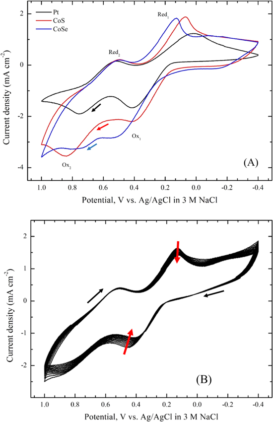
Figure 6A shows cyclic voltammograms for CoS and CoSe electrodes prepared by the approach described above in 0.1 M LiClO4 containing 10 mM LiI and 1 mM I2. For comparison, a voltammogram obtained using a Pt foil electrode is also shown in Fig. 6A. As shown in the figure, two pairs of oxidation and reduction peaks were observed in all the voltammograms. The pair of peaks Ox1 and Red1 at relatively negative potentials could be attributed to redox reaction 2 and the other peaks Ox2 and Red2 at more positive potentials were assignable to reaction 3:3,19,23


Since the main role of the counterelectrode in DSSCs is to effectively catalyze the reduction of I3– to I–, the redox peaks Ox1 and Red1 were analyzed based on the reduction current density (JRed) and the peak-to-peak potential separation (Epp). Generally, larger JRed and smaller Epp are diagnostic of better electrocatalytic activity.21 Values for JRed and Epp (Table I) increased in the order: Pt < CoSe < CoS and Pt < CoS < CoSe, respectively, demonstrating the comparable electrocatalytic performance for the electrodeposited CoS electrode to the Pt "standard." The improved electrochemical activity of electrochemically deposited CoS and CoSe electrodes may largely be due to a higher active surface area, in agreement with previous results.19
Figure 6. (A) Cyclic voltammograms for Pt, CoS and CoSe electrodes, and (B) Twenty consecutive cyclic voltammograms for a CoS electrode. All voltammograms were run in acetonitrile containing 0.1 M LiClO4, 10 mM LiI and 1 mM I2. Potential scan rate: 20 m V s−1.
Download figure:
Standard image High-resolution image
Table I. Comparison of electrocatalytic activities of counterelectrodes for the reduction of I3− to I−.a)
| Pt | CoS | CoSe | |
|---|---|---|---|
| JRed (mA cm−2) | 1.235 | 1.875 | 1.825 |
| Epp (mV) | 285 | 355 | 407 |
a)Data from Fig. 6A.
To assess electrochemical stability, twenty consecutive cyclic voltammograms were obtained for the CoS electrode in an acetonitrile solution containing 0.1 M LiClO4, 10 mM LiI and 1 mM I2 as shown in Fig. 6B. No substantial changes in JRed and Epp were observed for the CoS electrode after 20 cycles, indicating good electrochemical stability. A linear relationship between current density of Ox1 (or Red1) and square root of the scan rate was observed using the CoS electrode (not shown). This implies that the redox reaction is diffusion limited for the transport of the I−/I3− redox couple and there is no specific interaction between the redox couple and CoS electrode surface.
Conclusions
In summary, CoS and CoSe films were successfully electrosynthesized by the two-step approach using S- or Se-modified electrode in a Co2+-NTA complexing electrolyte. NTA was employed to shift the Co deposition potential to more negative potentials, and consequently, excess Co co-deposition could be avoided. Thus, stoichiometric CoQ (Q = S or Se) films with the component elements in a 1:1 ratio could be electrosynthesized without any post-deposition step unlike in previous studies. The as-synthesized CoS and CoSe films were successfully applied for the reduction of triiodide ions and found to be promising counterelectrode materials for possible use in DSSCs. Finally, the approach described here can be utilized for the facile synthesis of other metal chalcogenides in general.
Acknowledgments
This research was supported by the Basic Science Research Program through the National Research Foundation of Korea (NRF), Ministry of Education (Grants NRF-2016R1D1A1B02010133 and NRF-2018R1D1A1B07040855). We thank the two anonymous reviewers for constructive criticisms of an earlier manuscript version.