Article

Three-Dimensional Graphene Hybrid SiO2 Hierarchical Dual-Network Aerogel with Low Thermal Conductivity and High Elasticity

1
College of Aerospace Science and Engineering, National University of Defense Technology, Changsha 410000, China
2
Department of Scientific Research and Production, Beijing Institute of Spacecraft Environment Engineering, Beijing 100000, China
3
College of Civil Engineering and Mechanics, Lanzhou University, Lanzhou 730000, China
4
Key Laboratory of Mechanics on Disaster and Environment in Western China (Lanzhou University), The Ministry of Education of China, Lanzhou 730000, China
*
Author to whom correspondence should be addressed.
These authors contributed equally to this paper.
Coatings 2020, 10(5), 455; https://doi.org/10.3390/coatings10050455
Submission received: 17 February 2020 / Revised: 6 May 2020 / Accepted: 6 May 2020 / Published: 7 May 2020

Abstract

:
We describe lightweight three-dimensional (3D) graphene hybrid SiO2 aerogels (GSAs) with hierarchically robust interconnected networks fabricated via an in situ deposition procedure after a hydrothermal assembling strategy with graphene oxide sheets. The nano-/micron-thick SiO2 coating conformably grew over porous graphene templates with two constituents (e.g., graphene and SiO2) and formed chemically bonded interfaces. In addition, it significantly refined the primary graphene pores by hundreds of microns into smaller porous patterns. Studies of its mechanical properties verified that the graphene interframework made the ceramic composites elastic, while SiO2 deposition enhanced the strength required it to resist deformation. The higher SiO2 contents resulted in lower elasticity but larger strength because of the apparent nanosize effect of SiO2 ceramic thickness; GSAs with a density of 82.3–250.3 mg/cm3 (corresponding to SiO2 sol with concentration ranging from 5 to 20 wt %) could reach a good balance of strength and elasticity. Benefiting from hierarchical micronetworks consisting of semiclosed or closed pores, GSAs offer excellent thermal-insulation performance, with thermal conductivity as low as 0.026 W/(m·K). GSAs offer improved fire-resistant capacity rather than that of pure carbon-based aerogels via the synergic protection of SiO2 ceramic accretion. This highlights the promising applications of GSAs as lightweight thermal-shielding candidates for industrial equipment, civil architectures, and defense transportation vehicles.

1. Introduction

Thermal-insulation materials are increasingly needed, and have been derived from natural resources or synthetic products [1]. The most popular thermal insulators are currently organic (e.g., expanded polystyrene foam, phenolic foam, and polystyrene foam) or inorganic (e.g., carbon foam, foam glass board, vermiculite, foam concrete, and foam ceramic) with highly porous structures that generated low thermal conductivity (0.032–0.10 W·m−1·K−1) [2,3,4,5,6]. In general, aircraft require lightweight and robust protective shields to survive high-temperature flights, while civil architectures or industrial facilities use thermal-insulation materials to retain suitable temperatures [1,3,7]. However, most conventional ceramic insulators have poor elasticity that compromise possible deformation under complex mechanical–thermal fields, while organic or carbon components usually have low flaming retardancy and thermal stability under high temperature in aerobic conditions [6,7,8]. These issues have led to major tragedies, including that of the space shuttle Columbia, due to local cracks—the final failure was due to the intrinsic brittleness of ceramic-based insulation materials [9].
Therefore, insulating materials are not only expected to have a low thermal conductivity, large thermal stability, and flaming resistance, but also require a sequence of desired properties under mechanical–thermal coupling conditions including good elasticity, high strength, and infrared region [2,3,5,7,8,10]. Normally, either the thermal or mechanical properties of materials are dominated by their components and microstructures. The component basically determines the heat-transfer/-absorption format or deformation evolution on the atomic scale, while topological characteristics of the microstructures influence the heat- or load-transfer pathway [11,12]. This means that the desired functional materials can be created via suitable assembly strategies of chemical components and the rational design of geometric structures [13,14,15,16].
Three-dimensional (3D) graphene oxide (GO) monoliths have an orderly hierarchical structure, low thermal conductivity, high infrared absorption, and good mechanical elasticity [17,18,19,20]. They are promising thermal insulators compared to traditional silica-based ceramic aerogels [12]. However, low flame retardancy and thermal stability in air conditions make 3D graphene monoliths unsuitable for high-temperature and aviation environments [21,22]. Fortunately, these shortcomings can be improved if ceramic-like components are used [8,22]. In particular, graphene fillers significantly enhance the elasticity of ceramic-based composites by impeding crack propagations on multiple scales [8]. Therefore, in this article, to achieve synergic improvements in mechanical properties and thermal barriers for both graphene- and ceramic-based insulation materials, 3D lightweight graphene hybrid SiO2 aerogels (GSAs) were fabricated through an in situ deposition method. The 3D graphene architectures are an ideal porous template and elastic skeleton offering an orderly hierarchical structure, while the SiO2 ceramic component serves as thermal protective and mechanical strengthening accretion. Such hybrid aerogels offer low thermal conductivity, remarkable thermal stability, good flame retardance, large mechanical elasticity, and high strength, suggesting that these materials have value in, for example, refrigerator insulation board, building insulation layers, and aircraft thermal barrier.

2. Materials and Methods

2.1. Materials

Natural graphite flakes with average lateral diameters of 270 μm were commercially purchased from Nanjing Xianfeng Nanomaterials Tech. Co., Ltd. (Nanjing, China) to prepare a graphene oxide precursor [12]. The alkaline-type SiO2 sol precursor (mSiO2:nH2O, SiO2 ≤ 40%, Na2O ≤ 0.3%, density 1.28–1.30 g/cm3, pH 9.0–10.5, grain size 8–15 nm) was obtained from Dezhou Jinghuo Tech. Glass Co., Ltd. (Dezhou, China). Solvent alcohol, concentrated sulfuric acid, potassium permanganate, hydrochloric acid, ethylenediamine (EDA), and deionized water were all obtained from local suppliers (Lanzhou, China), and used as received.

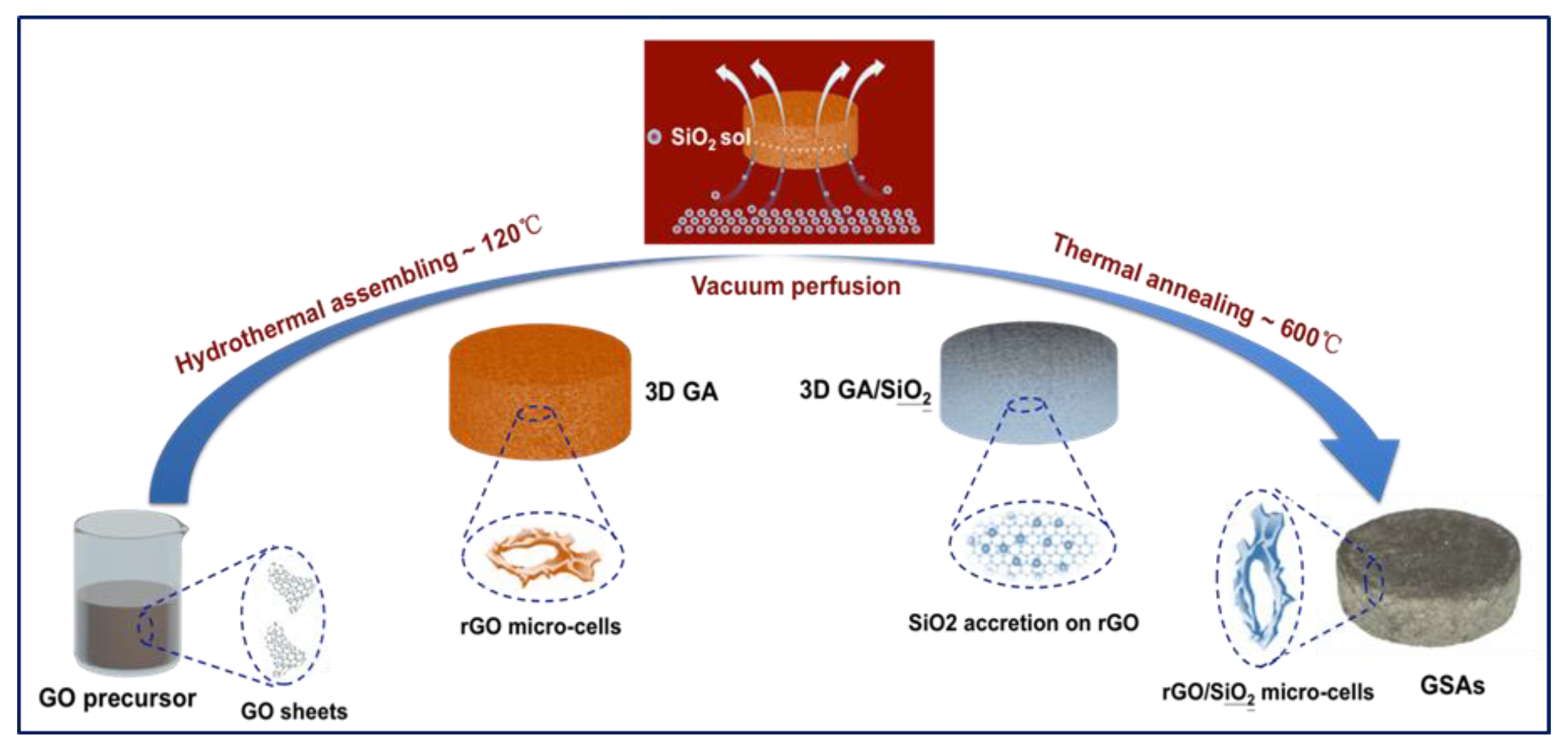
2.2. GSA Fabrication

The GO aqueous suspension (concentration 5 mg/mL) with an average lateral size up to hundreds of microns was synthesized via a modified Hummer’s method using natural graphite flakes (50 mesh) as the basic precursor for fabrication of 3D porous graphene templates [12]. A mixture of 40 mL GO sol and 200 μL EDA (volumetric ratio of 1:0.005) was uniformly dispersed with ultrasonic treatment (Figure 1). EDA as crosslinking agent was used to assist the assembly of GO sheets though the open-ring reaction between epoxy groups on GO and the amino groups of EDA [8]. The mixture was then transferred into a Teflon mold and hydrothermally assembled at 120 °C for 6 h with micron-scale GO sheets self-constructed into a 3D elastic hydrogel. The 3D porous GO sample with hierarchical microstructures was obtained after 24 h of dialysis in ethanol solution (20 vol %), followed by freeze-drying. The SiO2 sol with six different concentrations (0 wt %, 1 wt %, 5 wt %, 10 wt %, 20 wt %, 30 wt %, and 40 wt %) was then selected to fully absorb into the porous frameworks of 3D GO architecture under vacuum conditions, respectively. Subsequently, the elastic hydrogel-like composite of 3D GO architecture and SiO2 sol was treated by freeze-drying process at −60 °C for 24 h under vacuum conditions (1 Pa) with the contained water removed. After further thermal annealing at 600 °C for 8 h, three-dimensional (3D) lightweight GSAs (size: diameter × thickness = 30 mm × 11 mm) were fabricated with two constituents (i.e., reduced graphene oxide and SiO2) tightly composed together; the corresponding samples were marked as GSA-x (where x = 0, 1, 5, 10, 20, 30, and 40, respectively). Similarly, the reference pure SiO2 sample was prepared with SiO2 sol (concentration 40 wt %) by direct freeze-drying process at –60 °C for 24 h under vacuum conditions followed by thermal treatment at 600 °C for 8 h.

2.3. Characterizations and Measurements
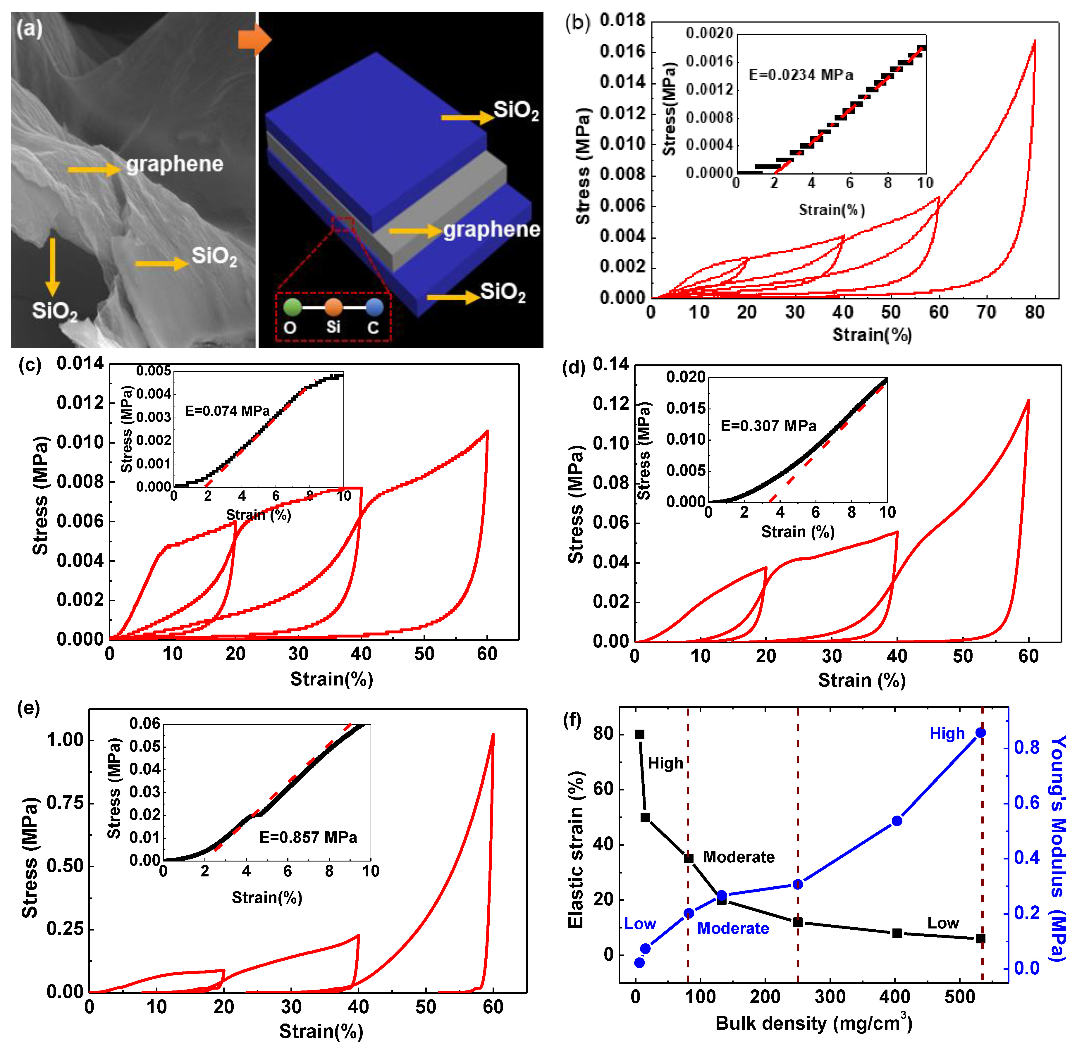
The material structures were studied with a scanning electron microscope (SEM, Apreo S, ThermoFisher, Waltham, MA, USA), and a transmission electron microscope (TEM, Tecnai G2 F30, FEI, Hillsboro, OR, USA). The elemental-distribution maps were obtained by an energy dispersive spectrometer (EDS, ThermoFisher). XRD analysis was conducted with an X-ray diffractometer (X’Pert Pro MPD, Malvern Panalytical, Malvern, UK). The chemical composition of GSAs was detected by X-ray photoelectron spectroscopy (XPS, 5700, Phi., Waltham, MA, USA). The chemical-bond evolutions of GSAs with different SiO2 contents were investigated by Fourier transform infrared (FTIR) spectroscopy (Nexus 670, Thermo Nicolet, Madison, WI, USA). Thermal stabilities under either air or vacuum conditions were studied using a thermogravimetric analyzer (TGA; STA 449C, Netzsch, Selb, Germany). Thermal conductivities were measured by a hot-wire-based thermal-conductivity meter (TC3000, Xiaetch, Xi’an, China). Thermal-insulation performance was verified with a thermal infrared imager (869, Testo, Lenzkirch, Germany).

3. Results

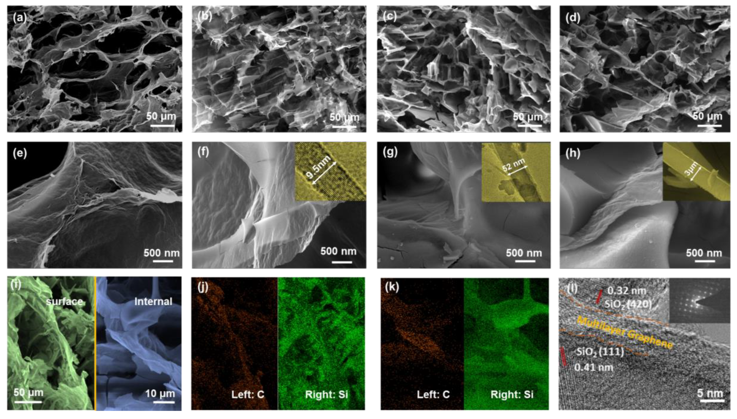
3.1. Microstructural Characterizations

The morphologies of the GSA samples with different SiO2 contents were studied by SEM and TEM observations. Figure 2a–d shows that the primary GA exhibited typical honeycomb-like and interconnected microstructures with pore dimensions that ranged from hundreds of nanometers to tens of microns. After processing the two constituents, GSA microstructures not only maintained the honeycomb patterns of GA template, but also had changes in pore shape and size; GSA pore changed to quadrangle from the primary circle shape of the graphene template, with the initial larger size divided into dual networks on a smaller scale. Figure 2e–h shows the sandwiched pore walls with the SiO2 layer conformably accreted over the rippled graphene sheets that served as basic construction elements to assemble into Y-shaped microjoints that then propagated into monolithic GSAs. The cracks that appeared in Figure 2c,g possibly were induced by shrinkage process during the freeze-drying and thermal annealing treatments with both free and bound water removed. By increasing SiO2 sol concentrations, the wrinkled coverage of the SiO2 ceramics wrapped around the graphene sheets. Related thickness was enlarged from several nanometers up to a few microns with the possible cracks on SiO2 layer synchronously suppressed. Figure 2i–k demonstrates the highly coincidental elemental patterns of EDS mappings corresponding to carbon (C) and silicon (Si) for the surface and internal positions of the GSAs, respectively. The weight percentage of Si in the internal regions was 38.60 wt %, while the surface content presented a slight increase of 41.73 wt %. Both silica-percentage and element-mapping results indicated the uniform attachment of SiO2 over 3D interconnected GA templates. Moreover, Figure 2l shows a typical high-resolution image of TEM and the selected area electron-diffraction pattern of the SiO2 ceramic; the corresponding distances for the (420) and (111) crystal planes were 0.32 and 0.41 nm, respectively. These two phases of SiO2 normally have catastrophic effects on thermal cycling. The sandwiched graphene sheets serving as reinforcing units were designed to improve the brittleness nature of SiO2 under thermal stresses [8].

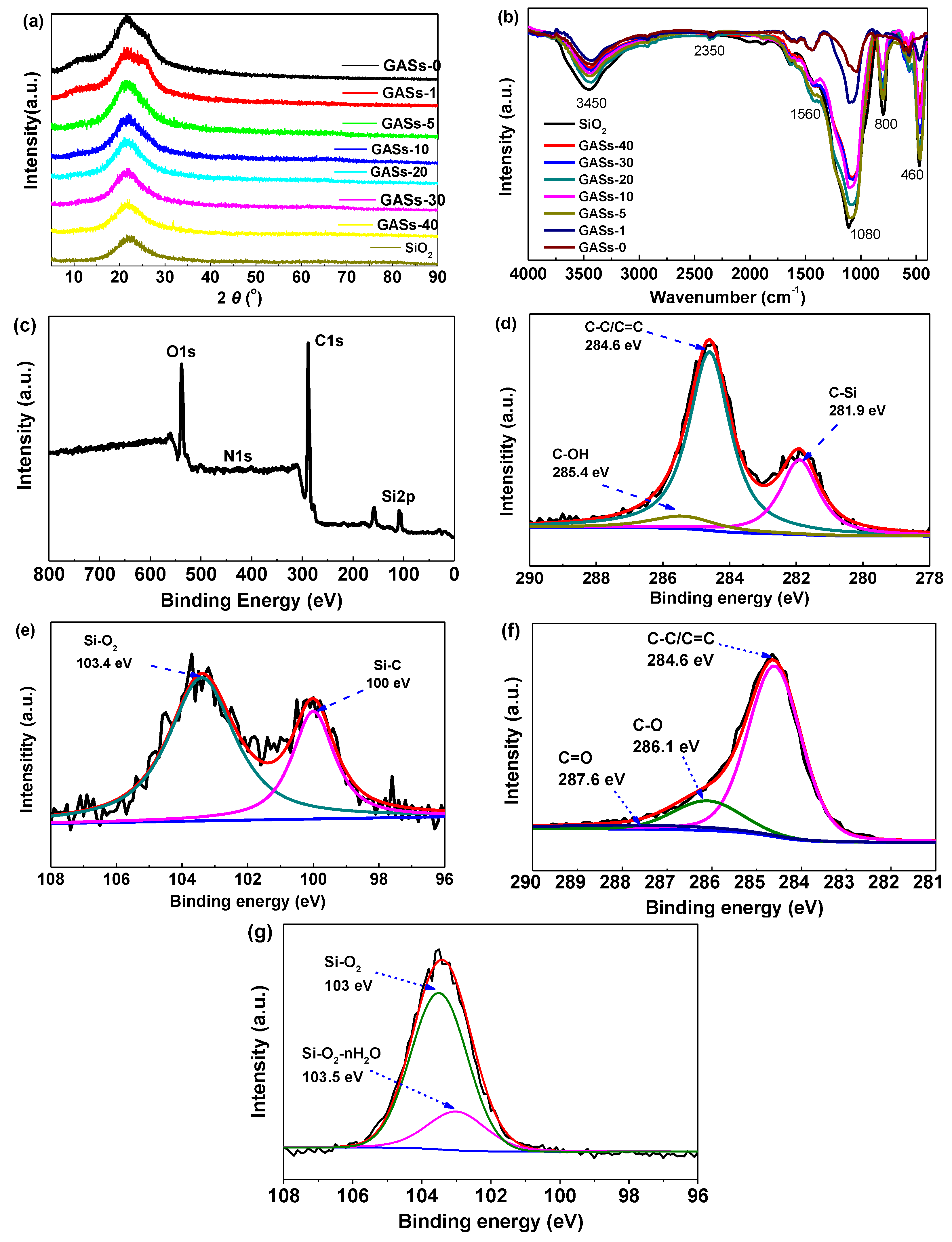
3.2. Chemical Composition and Structural Analysis

The GSAs were constituted with two different components, graphene sheets and SiO2 ceramic; the graphene sheets formed a 3D interconnected porous architecture with layered SiO2 conformably deposited over it. The chemical composition and structural characterization of GSAs were further examined with XRD and FT–IR investigations. As shown in Figure 3a, compared with GO typically peaked at around 10° [12], a wide peak of GSA-0 around 20° was generated through two peaks overlapping the graphitic peak at 26.52° and graphitic oxide less than 20°, because rGO sheets were partially reduced with a certain amount of oxygen-containing functional groups removed during thermal annealing at 600 °C. With the increase of SiO2 contents, GASs presented a sharp characteristic peak at 2θ = 21.5° due to SiO2 dominantly covering the peak information of the rGO component, which corresponded to the (002) plane of the graphitic structure and overlapped with the (222) plane of SiO2 [23]. This implied that the graphene component within the GSAs was partly reduced with a portion of oxygen functional groups retained on GO sheets during the thermal-annealing process at 600 °C versus 2θ = 26.52° for the intrinsic graphite (002) crystal plane [24].
Figure 3b demonstrates that the peak at 1560 cm−1 of the FT–IR spectra corresponded to the vibration of C–C/C=C, which was generated from the graphene sheets. The other characteristic peaks of 1080 and 460 cm−1 represent the symmetric and asymmetric stretching vibrations of Si–O bonds, respectively. The peak at 3450 cm−1 verified the existence of –OH stretching bonds, while the 2350 cm−1 peak was related to residual CO2. The peak at around 800 cm−1 corresponded to the stretching mode of Si–C bond. As shown in Figure 3c, the wide XPS spectrum peaks at 520, 280, and 103 eV were coincident with oxygen (O 1s), carbon (C 1s), and silicon (Si 2p), indicating the existence of 3D graphene architectures and the SiO2 component. The weight percentage of silica was 39.5 wt %, which was coincident with EDS results. The peak at 400 eV belongs to nitrogen (N 1s) formed during the crosslinking process of EDA with the GO sheet. The deconvolution of the C 1s spectrum in Figure 3d gives three typical peaks centered at 281.9, 284.5, and 285.4 eV, corresponding to dominant components within GSAs such as the Si–C bonds, C–C/C=C for aromatic carbon on GA, and slightly residual oxygen-containing groups of C–OH on reduced GO sheets, respectively. Similarly, both peaks in the Si 2p spectrum, located at 103.4 and 100 eV, are attributed to O–Si and C–Si, respectively [25,26] (Figure 3e). Both the C1s and Si 2p spectra agreed well with XRD and FT–IR data, and even further verified the formation of a covalent bond C–Si at the interface between graphene architecture and SiO2 ceramic layer. This interface facilitated the structural robustness and co-operative reinforcement of mechanical properties. Moreover, the deconvolution XPS spectrum of C 1s for GAS-0 gave typical peaks of 284.6, 286.1, and 287.6 eV corresponding to bonds of C–C/C=C, C–O, and C=O, respectively (Figure 3f). The Si 2p of SiO2 demonstrated bonds of Si–O and Si–O–nH2O referring to peaks of 103 and 103.5 eV, respectively (Figure 3g).

4. Discussion

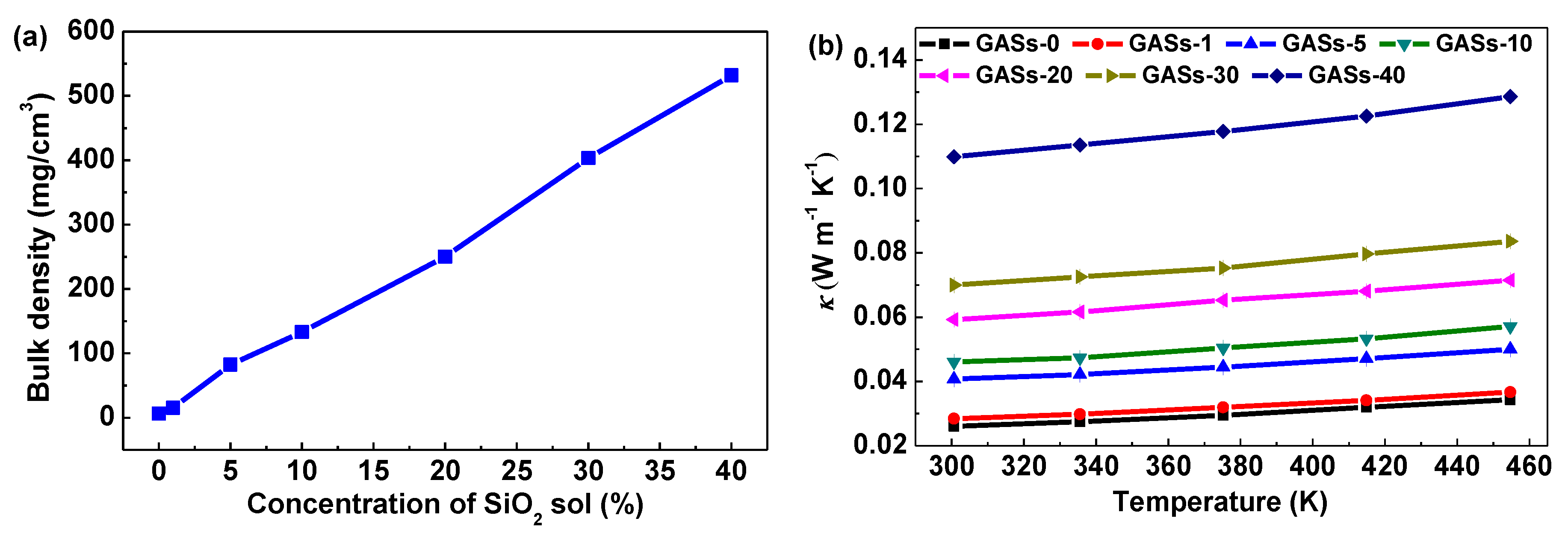
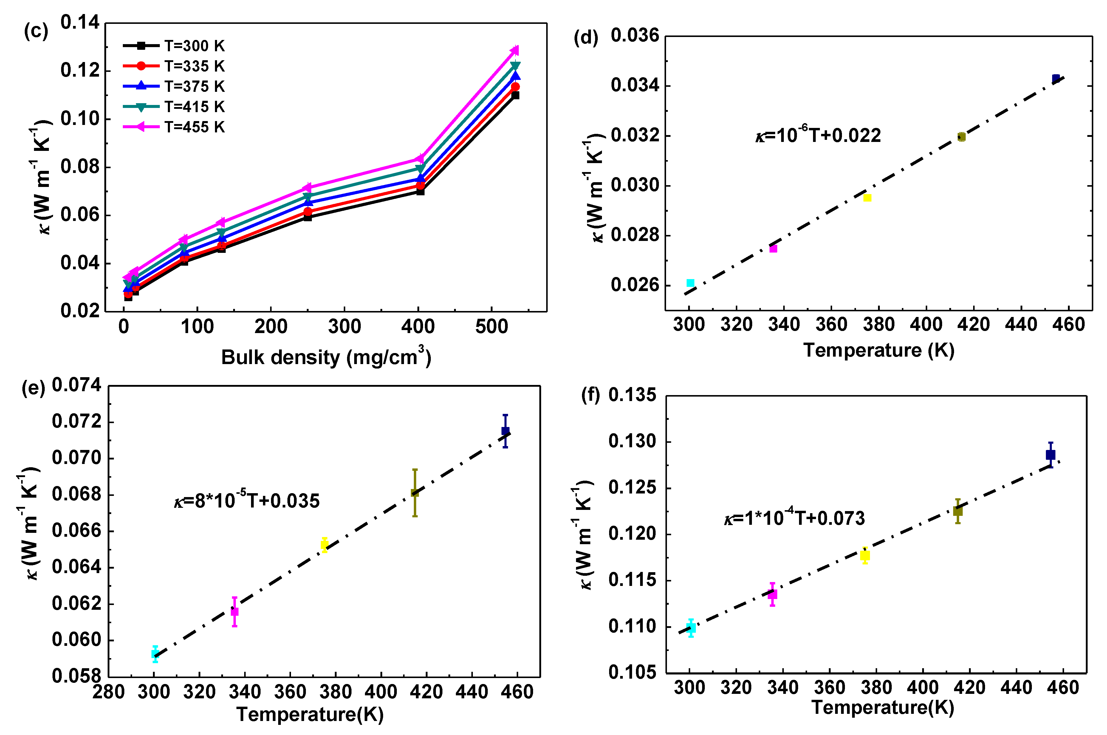
4.1. Investigation of Thermal-Conductivity Properties

We implemented measurements of sample mass (m) by digital high-precision balance (accuracy 0.001 mg), while the volume (V) of the pancake-shaped sample was obtained using a digital micrometer (accuracy 0.01 mm). The apparent density of the sample was calculated directly by m/V. As shown in Figure 4a and Table 1, the bulk densities, relative density, and SiO2 content of the GSAs were linearly dependent on SiO2 sol concentration from 0 to 40 wt %. This led to porous GAS architectures via a perfusion process under vacuum conditions. They were enlarged from 6.5 mg/cm3 of GA towards 532 mg/cm3. To understand the thermal-insulation performance of the GSAs, thermal conductivity (κ, W m–1 K−1) was investigated on the basis of the hot-wire method. κ significantly depended on the bulk density of GSAs as value increased from 0.026 to 0.11 W·m–1·K−1 at room temperature (RT; Figure 4b,c). The value at 300 K corresponded to the bulk-density range of 6.5–532 mg/cm3. The higher concentration meant that more SiO2 was deposited over the GA template, leading to a thicker SiO2 layer and more pathways for thermal transfer.
At RT conditions in air, the thermal-insulation capacities of GSAs were obviously divided into three categories according to their densities. At densities lower than 100 mg/cm3, the minimal κ was about 0.026 W·m–1·K−1 for bulk density, implying outstanding thermal insulation for this lightweight graphene/SiO2 hybrid aerogel versus most natural or artificial insulation candidates [3], such as expanded polystyrene foam (0.04 W·m–1·K−1), vermiculite (0.044 W·m–1·K−1), phenolic foam board (0.032 W·m–1·K−1), polystyrene foam (0.041 W·m–1·K−1), foam glass board (0.062 W·m–1·K−1), fiber-reinforced composite (0.07 W·m–1·K−1), foam concrete (0.24 W·m–1·K−1), and foam ceramic board (0.10 W·m–1·K−1). κ continuously increased up to 0.07 W·m–1·K−1 on the basis of density values (100–400 mg/cm3). However, this slow increase of κ versus density tended to markedly depend on κ being larger than 0.1 W·m–1·K−1, as well as density beyond 400 mg/cm3, suggesting a slight decay in the thermal-insulation ability of the denser GSA structure. The impact of density on the material structure, including pore geometric shape and size, did not follow a linear relationship. Thermal conductivity was mainly determined by structural characteristics, so it could not realize ideal linear fitting curves of density vs. κ. As illustrated in Figure 2f–h, the abrupt increase of thermal conductivity for GASs with densities above 400 mg/cm3 was due to the remarkable enlargement of the SiO2 layer’s thickness deposited over the GA framework, which significantly improved the continuity of the microbranches of graphene- and SiO2-composited walls. In addition, due to the combined effects of hot electron activation, radiation conduction, and convection conduction [12], κ increased 18.2%–34.1% with the surrounding temperature increasing from 300 to 500 K.
Figure 4d–f shows a mathematical fitting operation based on the least-squares method. The κ of all GSA samples with seven different densities nicely followed a linear function format of temperature variations as κ = AT + B (where both A and B were constants). At GSA density of 6.5 mg/cm3, A and B values were 1.0 × 10⁻⁶ and 0.022, respectively. Both A and B were enlarged as long as temperature increased. For instance, A and B further increased up to 8.0 × 10⁻⁵ and 0.035, respectively, corresponding to a density of 270 mg/cm3. Moreover, the as-obtained densest GSA (532 mg/cm3) resulted in the largest values for A and B of 1.0 × 10⁻⁴ and 0.073, respectively.

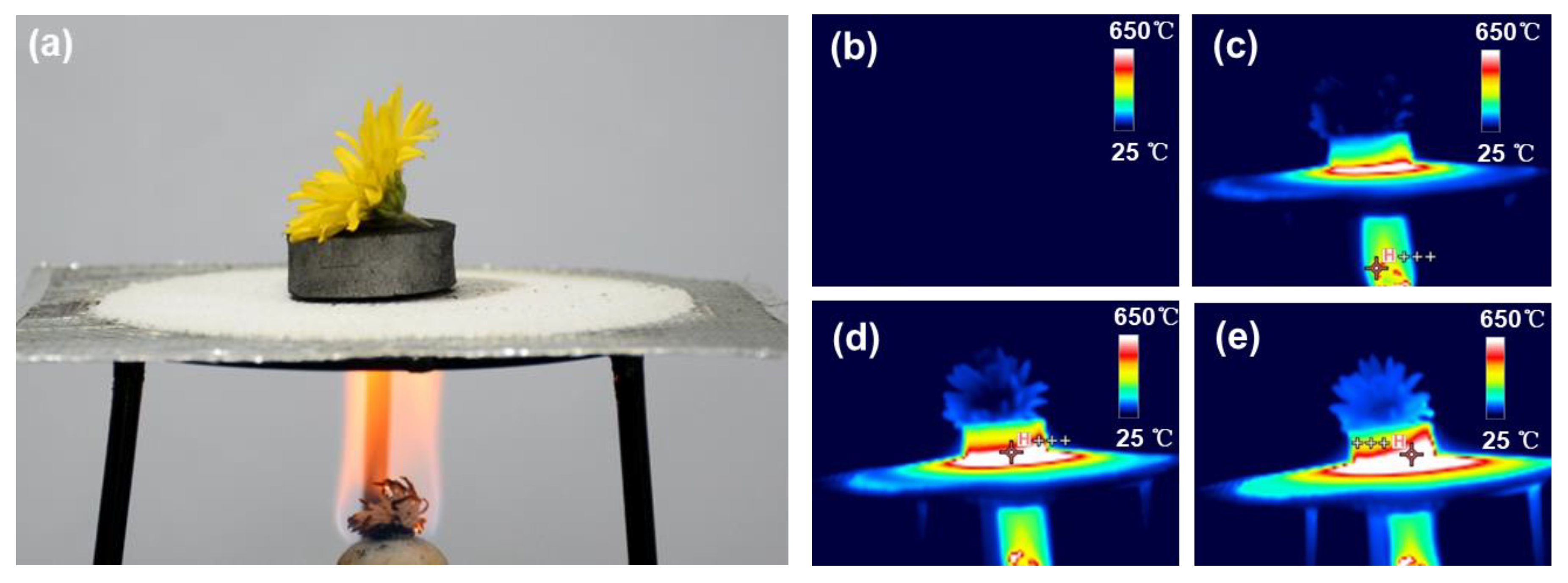
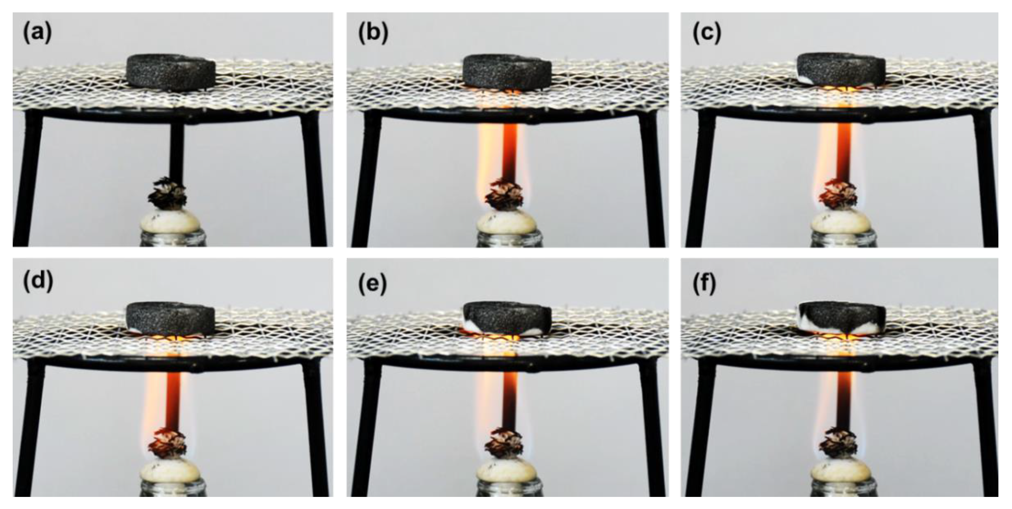
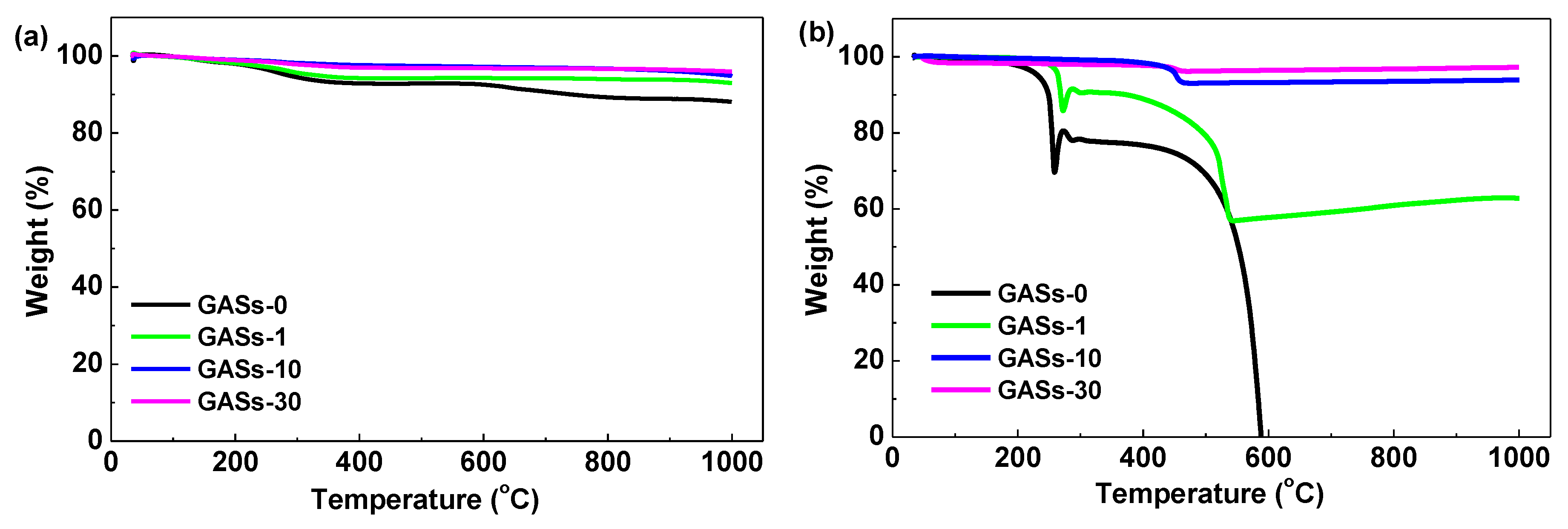
4.2. Thermal-Insulation, Flame-Resistance, and Thermal-Stability Studies

GSAs are an insulating material in thermal engineering. Figure 5a demonstrates the experiment setup of GSA thermal-insulation performance with a pie-shaped sample placed over an asbestos-free wire gauze that is was directly heated by an alcohol lamp; GSA-10 was selected as the representative sample for followed investigation. To visually illustrate thermal-insulation properties, a fresh chrysanthemum flower was placed over the GSA sample. Temperature distribution throughout the system was captured by a digital infrared camera. Figure 5b shows infrared images of both the GSA sample and the flower, they were almost the same as the room-temperature background. Once the lamp was lighted, temperature at the bottom of the GSAs was rapidly elevated to over 650 °C within 10 min, but the flower maintained the same temperature as the surrounding environment (see Figure 5c,d). Even though the GSAs were heated over 30 min, the gradual increase in temperature over the flower was less than 10 °C, with its original shape remaining fresh and nonshrinkable. This implies that porous GSAs have excellent thermal-insulation capabilities, and block heat transfer from hot to cold. Moreover, GA composition could absorb infrared radiation to suppress the infrared thermal transform and further make up the shortage of infrared transparent properties in normal pure SiO2 ceramic aerogels [27,28].
Furthermore, the combination of SiO2 ceramic with GA could improve thermal stability and flame resistance under air conditions because the pure carbon nanomaterial could not tolerate the oxidizing reaction with direct contact of oxygen at temperatures over 350 °C [29,30]. Figure 6 shows that the GSA sample was directly ablated by alcohol lamp fire with the outer flame temperature over 650 °C. Figure 6a shows the primary black and regular geometric configuration of GSA-10. The sample retained its original color and regular shape within the first 10 min. After 20 min, there was a slight color change at the edges from black to white; this indicated that a very small portion of the GA was thermally etched. At 50 min, about 20% of the black region became white, and the sample did not burn. This is attributed to the synergetic protection of SiO2 ceramic accretions over GA microframework. The flame resistance of GSA was significantly improved versus that of pure carbon nanomaterials that are flammable at 350 °C [8]. Moreover, despite the GA that was partially oxidized by flames, the pielike GSA sample always retained its regular geometric configuration and robust structure without any visible volumetric shrinkage or structural fractures.
The improvement in GSA thermal stability versus that of pure GA under the thermal-protective deposition of SiO2 ceramic was evaluated by TGA investigation as temperature increased from RT to 1000 °C. Figure 7a shows the weight losses for GSAs. They decreased from 11.03% for the pure GA to 7.04% for GSA-1 at N2 atmosphere conditions. There was an increase in SiO2 ceramic contents with eventual weight losses at 1000 °C, less than 4% for GSA-30. This indicated that the SiO2 ceramic combination could enhance the thermal stability of GA-based functional insulation materials. In contrast, for GSA samples exposed to air conditions, both pure GA and GSA-1 exhibited typical TGA curves, with the first weight-loss stage occurring at 250 °C because of the decomposition of oxygen-containing residues remaining on the rGO. Subsequently, the most dramatic weight drops appeared at temperatures from 500 to 600 °C due to the partial oxidation of the carbon components in GSAs. However, for GSA-10 and GSA-30, the final weight losses at 1000 °C decreased to 6.13% and 3.7%, respectively. This clearly demonstrated the existence of the SiO2 ceramic constituent that gives the GSAs outstanding thermal stability for either air or inert atmosphere conditions—there was no direct contact between GA and oxygen. Comparatively, 10 wt % SiO2 sol-derived GSA-10 already presented excellent thermal stability with a weight drop in air conditions less than 7% at 1000 °C.

4.3. Investigation of Mechanical Properties

Lightweight insulation materials are mostly expected to have good elasticity to make up for possible deformation under complex thermal–mechanical coupling fields [7,8]. As schematically illustrated in Figure 8a, to improve the intrinsic brittleness of SiO2 ceramics, 3D graphene frameworks were used as a highly porous template for SiO2 deposition. Here, the sandwiched graphene skeletons served as the reinforcing components to suppress the possible crack propagation of the SiO2 ceramic, making GSAs synergistically realize good elasticity and high strength. Studies of GSA mechanical properties were conducted via a static compressive machine with a step-loading scheme (compression strain = 20%, 40%, 60%, and 80%) and a loading rate of 1 mm/min.
Figure 8b shows that the GA could elastically deform with a maximal strain as large as 80%; the primary structure was not damaged, indicating outstanding elasticity to overcome a large deformation of the hierarchical structure on the multiscale. However, pure GA showed a relatively low Young’s modulus of 0.023 MPa, the stepped increases of compressive strength (0.0026, 0.0041, 0.0067, and 0.0170 MPa corresponding to strains of 20%, 40%, 60%, and 80%) demonstrated a typical intensification effect as similar as most insulation materials (Table 2) [31,32]. Comparatively (Figure 8c), with a combination of SiO2 constituents, GSA-1 showed a nearly 300% increase in Young’s modulus (0.074 MPa) and over 200% enhancement of compressive strength (e.g., 0.006 MPa for strain of 20%). However, the elastic region for GSA-1 decreased to 50% elastic strain (Table 3). Both Young’s modulus and compressive strength increased with more SiO2, but elasticity conversely decreased (Figure 8c,d). For example, the Young’s modulus and compressive strength of GSA-20 were 0.307 and 0.0376 MPa, respectively, but the maximal elastic strain dropped to 12% (Figure 8d). Such balance for strength and elasticity attributed to collaborative contributions between elastic contributor GA and strengthening component SiO2. Therefore, once the SiO2 content was larger than that of GSA-20, GSA elasticity was dominated by the intrinsic brittle ceramic with a maximal elastic strain lower than 10% (Table 3). Nevertheless, the strength of GSA-40 at 60% strain was larger than 1 MPa, facilitating promising applications in structural materials with good thermally protective functions (Table 2).
Furthermore, both elastic strain and Young’s modulus of the GSAs were directly dependent on the contents of SiO2 and bulk density (Figure 8f). These are essentially determined by the thickness of the SiO2 layer deposited over the graphene sheets within GSA microstructures (Figure 2). Specifically, the density for GSA-1 was about 15.3 mg/cm3 corresponding to SiO2 layer thickness of a few nanometers (Figure 2f). In this case, GSAs exhibited the highest elasticity of over 50% but the lowest Young’s modulus (less than 0.1 MPa). As density ranged from 82.3 for GSA-5 to 250.3 mg/cm3 for GSA-20, GSAs presented moderate elasticity (12%–30%) and Young’s modulus (0.202–0.307 MPa; the thickness of SiO2 deposition was enlarged from 9.5 to 52 nm; Figure 2f,g). In contrast, at a density of over 300 mg/cm3, GSA-30 elasticity severely dropped to less than 10%, while the mechanical Young’s modulus significantly increased up to the 1 MPa order. This corresponded to SiO2 deposition of up to 3 microns (Figure 2h).
This three-scheme characteristic of elastic strain and Young’s modulus relying on bulk densities emphasizes the size effect of the microelement scale on mechanical properties. Fundamentally, versus either pure GA or SiO2 aerogel, GSAs presented higher elasticity and Young’s modulus because of the coordinated enhancement of the two-composite constituents. GA is the reinforcing unit that can suppress crack propagation of brittle SiO2. This makes GSAs more elastic under large-scale deformation. Simultaneously, SiO2 deposition over graphene sheets is the protective layer that can enlarge the inertia moment of the basic pore wall in the microstructure. This can markedly enhance compression resistance via microelement bending deformation. Results suggested a feasible way to create a graphene-based ceramic composite with expected mechanical properties via a multiscale structural design and rational composition process [7,8].

5. Conclusions

We reported a three-dimensional lightweight GSA aerogel with hierarchical and robust structures via two constituents (i.e., graphene and SiO2) tightly composited together by chemical bonds at the Si–C interface bond. Due to the highly porous architectures and protective SiO2 accretion, the GSAs showed good thermal-insulation properties, with thermal conductivity as low as 0.026 W m−1 K−1, and significant improvements in thermal stability (weight losses < 10% at 1000 °C) and flame resistance. The sandwiched graphene interskeletons made GSAs more elastic (recoverable compression strain up to 50%) than pure SiO2 aerogels under direct crack-propagation suppression; SiO2 deposition obviously increased strength (up to 1 MPa) by enlarging the bending resistance of the micropore walls. Moreover, the mechanical properties confirmed the size effects on GSA elasticity and compressive strength of the SiO2 layer thickness from a few nanometers to several microns. This indicated that rational structure design and controllable fabrication on a multiscale create graphene-based ceramic composites with expected mechanical and thermal properties. They show promise for use in industrial equipment, civil architectures, and defense transportation vehicles.

Author Contributions

Conceptualization, Q.Z.; methodology, P.H.; validation, L.Z.; formal analysis, K.S. and B.Z.; data curation, R.H.; writing—original-draft preparation, Q.Z.; writing—review and editing, J.Z.; funding acquisition, L.Z. All authors have read and agreed to the published version of the manuscript.

Funding

This research was funded by the National Key R&D Program of China, grant No. 2019YFC1511005; National Natural Science Foundation of China, grant No. 51702142; the Science Fund for Distinguished Young Scholars of Gansu Province, grant No. 18JR3RA263; the Talent Innovation and Entrepreneurship Project of Lanzhou, grant No. 2019-RC-42; the 2019 Civil-Military Integration Project of Lanzhou, grant No. GF-2019-ZA-QT-05; the Fundamental Research Funds for the Central Universities, grant No. lzujbky 2019-81.

Conflicts of Interest

The authors declare no conflict of interest.

References

  1. Papadopoulos, A.M. State of the art in thermal insulation materials and aims for future developments. Energy Build. 2005, 37, 77–86. [Google Scholar] [CrossRef]
  2. Wicklein, B.; Kocjan, A.; Salazar-Alvarez, G.; Carosio, F.; Camino, G.; Antonietti, M.; Bergström, L. Thermally insulating and fire-retardant lightweight anisotropic foams based on nanocellulose and graphene oxide. Nat. Nanotechnol. 2015, 10, 277–283. [Google Scholar] [CrossRef] [PubMed]
  3. Jelle, B.P. Traditional, state-of-the-art and future thermal building insulation materials and solutions-properties, requirements and possibilities. Energy Build. 2011, 43, 2549–2563. [Google Scholar] [CrossRef] [Green Version]
  4. Yang, L.; Yang, N.; Li, B. Extreme low thermal conductivity in nanoscale 3D Si phononic crystal with spherical pores. Nano Lett. 2014, 14, 1734–1738. [Google Scholar] [CrossRef] [PubMed] [Green Version]
  5. Hüsing, N.; Schubert, U. Aerogels-airy materials: Chemistry, structure, and properties. Angew. Chem. Int. Ed. 1998, 37, 22–45. [Google Scholar] [CrossRef]
  6. Lee, B.I. Properties of low-density bulk silica gel: Lyosil. Mater. Lett. 1994, 19, 217–219. [Google Scholar] [CrossRef]
  7. Xu, X.; Zhang, Q.; Hao, M.; Hu, Y.; Lin, Z.; Peng, L.; Wang, T.; Ren, X.; Wang, C.; Zhao, A.; et al. Double-negative-index ceramic aerogels for thermal superinsulation. Science 2019, 363, 723–727. [Google Scholar] [CrossRef]
  8. Zhang, Q.; Lin, D.; Deng, B.; Xu, X.; Nian, Q.; Jin, S.; Leedy, K.; Li, H.; Cheng, G.J. Flyweight, superelastic, electrically conductive, and flame-retardant 3D multi-nanolayer graphene/ceramic metamaterial. Adv. Mater. 2017, 29, 1605506. [Google Scholar] [CrossRef]
  9. Mayeaux, B.M.; Collins, T.E.; Jerman, G.A.; McDanels, S.J.; Piascik, R.S.; Russell, R.W.; Shah, S.R. Materials analysis: A key to unlocking the mystery of the Columbia tragedy. JOM 2004, 56, 20–30. [Google Scholar] [CrossRef]
  10. Pettes, M.T.; Ji, H.; Ruoff, R.S.; Shi, L. Thermal transport in three-dimensional foam architectures of few-layer graphene and ultrathin graphite. Nano Lett. 2012, 12, 2959–2964. [Google Scholar] [CrossRef]
  11. Schaedler, T.A.; Carter, W.B. Architected cellular materials. Annu. Rev. Mater. Res. 2016, 46, 187–210. [Google Scholar] [CrossRef]
  12. Zhang, Q.; Hao, M.; Xu, X.; Xiong, G.; Li, H.; Fisher, T.S. Flyweight 3D graphene scaffolds with microinterface barrier-derived tunable thermal insulation and flame retardancy. ACS App. Mater. Interfaces 2017, 9, 14232–14241. [Google Scholar] [CrossRef]
  13. Li, Y.; Zhu, K.; Peng, Y.; Li, W.; Yang, T.; Xu, H.; Chen, H.; Zhu, X.; Fan, S.; Qiu, C. Thermal meta-device in analogue of zero-index photonics. Nat. Mater. 2019, 18, 48–54. [Google Scholar]
  14. Narayana, S.; Sato, Y. Heat flux manipulation with engineered thermal materials. Phys. Rev. Lett. 2012, 108, 214303. [Google Scholar] [CrossRef] [PubMed]
  15. Ramezanzadeh, B.; Haeri, Z.; Ramezanzadeh, M. A facile route of making silica nanoparticles-covered graphene oxide nanohybrids (SiO2-GO); fabrication of SiO2-GO/epoxy composite coating with superior barrier and corrosion protection performance. Chem. Eng. J. 2016, 303, 511–528. [Google Scholar] [CrossRef]
  16. Wang, R.; Zhuo, D.; Weng, Z.; Wu, L.; Cheng, X.; Zhou, Y.; Wang, J.; Xuan, B. A novel nanosilica/graphene oxide hybrid and its flame retarding epoxy resin with simultaneously improved mechanical, thermal conductivity, and dielectric properties. J. Mater. Chem. A 2015, 3, 9826–9836. [Google Scholar] [CrossRef]
  17. Hu, H.; Zhao, Z.; Wan, W.; Gogotsi, Y.; Qiu, J. Ultralight and highly compressible graphene aerogels. Adv. Mater. 2013, 25, 2219–2223. [Google Scholar] [CrossRef]
  18. Xu, Y.; Sheng, K.; Li, C.; Shi, G. Self-assembled graphene hydrogel via a one-step hydrothermal process. ACS Nano 2010, 4, 4324–4330. [Google Scholar] [CrossRef]
  19. Qiu, L.; Liu, J.Z.; Chang, S.L.; Wu, Y.; Li, D. Biomimetic superelastic graphene-based cellular monoliths. Nat. Commun. 2012, 3, 1241. [Google Scholar] [CrossRef] [Green Version]
  20. Zhong, Y.; Zhou, M.; Huang, F.; Lin, T.; Wan, D. Effect of graphene aerogel on thermal behavior of phase change materials for thermal management. Sol. Energy Mater. Sol. Cells 2013, 113, 195–200. [Google Scholar] [CrossRef]
  21. Yuan, B.; Sun, Y.; Chen, X.; Shi, Y.; Dai, H.; He, S. Poorly-/well-dispersed graphene: Abnormal influence on flammability and fire behavior of intumescent flame retardant. Compos. Part A 2018, 109, 345–354. [Google Scholar] [CrossRef]
  22. Wang, C.; Qiao, C.; Song, W.; Sun, H. Ultrafast spreading effect induced rapid cell trapping into porous scaffold with superhydrophilic surface. ACS Appl. Mater. Interfaces 2015, 7, 17545–17551. [Google Scholar] [CrossRef] [PubMed]
  23. Ding, Y.; Liu, Z.; Wang, F.; Liu, N. Heat-resisting and insulating properties of SiO2 aerogel modified silicone coating. J. Logist. Eng. Univ. 2016, 32, 77–83. [Google Scholar]
  24. Herzog, B.; Bokern, D.; Braun, T.; Schloegl, R.; Troyer, C. On the oxidation of graphite: An in-situ XRD-study. Mater. Sci. Forum 1994, 166–169, 517–522. [Google Scholar] [CrossRef]
  25. Namiki, A.; Tanimoto, K.; Nakamura, T.; Murayama, N.; Suzaki, T. Formation of interfacing Si-O-Si species by hydrogenated Si radical depositions onto oxidized Si(111) surfaces. Surf. Sci. 1988, 203, 129–142. [Google Scholar] [CrossRef]
  26. Nijs, J.M.M.D.; Silfhout, A.V. The Ti/C-Si solid state reaction: Ii. additional measurements by means of RBS, XPS and AES. Appl. Surf. Sci. 1990, 40, 349–358. [Google Scholar] [CrossRef]
  27. Fricke, J. SiO2-aerogels: Modifications and applications. J. Non-Cryst. Solids 1990, 121, 188–192. [Google Scholar] [CrossRef]
  28. Ruzicka, J.; Krupa, L.; Fadejev, V.A. On optical transition radiation of charged particles in SiO2-aerogels. Nucl. Instrum. Methods B 1997, 384, 387–402. [Google Scholar] [CrossRef]
  29. Yu, B.; Shi, Y.; Yuan, B.; Qiu, S.; Xing, W.; Hu, W.; Song, L.; Lo, S.; Hu, Y. Enhanced thermal and flame retardant properties of flame-retardant-wrapped graphene/epoxy resin nanocomposites. J. Mater. Chem. A 2015, 3, 8034–8044. [Google Scholar] [CrossRef]
  30. Sang, B.; Li, Z.; Li, X.; Yu, L.; Zhang, Z. Graphene-based flame retardants: A review. J Mater. Sci. 2016, 51, 8271–8295. [Google Scholar] [CrossRef]
  31. Gao, Q.F.; Feng, J.; Zhang, C.R.; Feng, J.Z.; Wu, W.; Jiang, Y.G. Mechanical properties of aerogel-ceramic fiber composites. Adv. Mater. Res. 2010, 105–106, 94–99. [Google Scholar] [CrossRef]
  32. Hong, C.Q.; Han, J.C.; Zhang, X.H.; Du, J.C. Novel nanoporous silica aerogel impregnated highly porous ceramics with low thermal conductivity and enhanced mechanical properties. Scr. Mater. 2013, 68, 599–602. [Google Scholar] [CrossRef]
Figure 1. Schematic of graphene hybrid SiO2 aerogel (GSAs) fabrication including grapheme oxide (GO) architecture formation by self-assembling GO sheets via hydrothermal chemical reaction. SiO2 sol absorbing into porous GO architecture and in situ freeze-drying combined with subsequently thermal annealing to form GSAs with graphene templates and SiO2 ceramics tightly integrated.
Coatings 10 00455 g001
Figure 2. (ad) SEM images of microstructural geometric pattern evolutions for GSAs fabricated by SiO2 sol concentrations of 0, 5 wt %, 20 wt %, and 30 wt %, respectively. (eh) Morphologies of micronodes presenting different combination formats between graphene sheets and SiO2 accretions as SiO2 sol concentrations increased from 0 to 30 wt % (insets in (fh) show thicknesses of SiO2 layers). (i) SEM image of selected area for EDS in GSA-10 (left, surface position; right, internal position). (jk) EDS mapping of elements (left) C and (right) Si. (l) TEM image with high-resolution diffraction (inset).
Coatings 10 00455 g002
Figure 3. Comparative chemical composition and structural characterizations. (a) XRD patterns of GSAs; (b) FT–IR spectrum of GSAs; (c) XPS survey with all the characteristic peaks of GSA-10; (d) and (e) deconvolution XPS spectrum of C1s and Si 2p of GSA-10, respectively. Deconvolution XPS spectrum of (f) C 1s of GAS-0 and (g) Si 2p of SiO2.
Coatings 10 00455 g003
Figure 4. Investigation of GSA thermal-insulation properties. (a) Relationship between bulk density versus concentration of perfusion SiO2 sol. (b,c) Effects of surrounding temperature (300–460 K) and bulk density on thermal conductivity, respectively. (df) Linearly fitting results for thermal conductivity as a function of surrounding temperature for GSA-x (x = 0, 20, and 40, respectively).
Coatings 10 00455 g004aCoatings 10 00455 g004b
Figure 5. Experiment investigation of GSA-10 thermal insulation under fire-heating conditions. (a) Experiment setup for GSA. Fresh flower was placed over a flame over its top side. (be) Temperature distribution for GSAs and entire configuration changes of flower after different heating times, including initial status, and 10, 20, and 30 min, respectively.
Coatings 10 00455 g005
Figure 6. Flame-resistance studies with GSA-10. (af) Visual configurations of the GSA sample after 10, 20, 30, 40, and 50 min, respectively, of ablation tests in air condition with alcohol lamp.
Coatings 10 00455 g006
Figure 7. Thermogravimetric-analysis (TGA) tests for thermal-stability investigation of GSAs (a) under N2 atmosphere and (b) in air.
Coatings 10 00455 g007
Figure 8. Mechanical properties of GSAs under compression deformation. (a) Graphene and SiO2-composited multilayer structure: (b) GSA-0, (c) GSA-1, (d) GSA-20, (e) GSA-40; and (f) impact of GSA bulk densities on elastic strain and Young’s modulus.
Coatings 10 00455 g008
Table 1. Bulk density, relative density, and SiO2 content of GSAs.
GSA-xx = 0x = 1x = 5x = 10x = 20x = 30x = 40
Bulk density (mg/cm3)6.215.382.3133.1250.3403.2532.1
Relative density (ρGASsair)4.811.863.7102.9193.6311.8411.5
SiO2 content (wt %)059.592.595.398.598.598.8
Table 2. Deformation intensification of compressive strength under different strains (MPa).
StrainGraphene Hybrid SiO2 Aerogels (GSA-x)
x = 0x = 1x = 5x = 10x = 20x = 30x = 40
20%0.00260.00600.01580.02280.03760.04550.0964
40%0.00410.00780.02350.03090.05660.05690.2390
60%0.00670.01070.03870.05040.12180.12211.0332
80%0.0170
Table 3. GSA elastic strain and Young’s modulus.
GSA-xx = 0x = 1x = 5x = 10x = 20x = 30x = 40
Young’s modulus (MPa)0.0230.0740.2020.2670. 3070.5370.857
Elastic strain (%)805030201286

