Article

Friction Mechanism Features of the Nickel-Based Composite Antifriction Materials at High Temperatures

1
Department of Lightweight Elements Engineering, Foundry and Automation, Wroclaw University of Science and Technology, Lukasiewicza 7-9 str., 50371 Wroclaw, Poland
2
Igor Sikorsky Kyiv Polytechnic Institute, National Technical University of Ukraine, 37 Peremogy ave., 03057 Kyiv, Ukraine
3
Department of Mechanics, Materials and Biomedical Engineering, Wroclaw University of Science and Technology, Smoluchowskiego 25 str., 50370 Wroclaw, Poland
4
Department of Technical Systems Operation and Maintenance, Wroclaw University of Science and Technology, Smoluchowskiego 48 str., 50372 Wroclaw, Poland
*
Author to whom correspondence should be addressed.
Coatings 2020, 10(5), 454; https://doi.org/10.3390/coatings10050454
Submission received: 9 April 2020 / Revised: 29 April 2020 / Accepted: 6 May 2020 / Published: 7 May 2020

Abstract

:
The friction behavior of the formed antifriction films and their effect on the functional properties of the composite based on the powder nickel alloy EI929 with solid lubricant CaF2 at high temperatures was investigated. An antifriction film was formed on the contact surfaces during the friction process. Such a film was the result of the interaction of the contact surfaces with atmospheric oxygen at high temperatures. It contains oxides of alloying elements from materials of the frictional contact and solid lubricant calcium fluoride. The quantitative ratio of formed oxides depends on the temperature operating conditions of material. The data of thermodynamic simulation of the high-temperature interaction of the composite with oxygen coincide with the experimental data obtained by studying the fine structure of surface antifriction films. Antifriction films consist of oxide phases in combination with solid CaF2 lubricant. Anti-friction films provide high wear resistance of the self-lubricating composite in the range of temperatures 1073–1173 K due to the balance between the rate of their formation and wear. When the temperature exceeds 1200 K, the film loses its lubricating properties and acts as an abrasive substance due to the intense oxidation. Abrasive surfaces of materials were subjected also to microscopic examination, in which the mechanically mixed layer (MML) was described. The study of the friction surface roughness parameters confirmed the presence of the formed friction self-lubricating film and allowed to determine its parameters. The friction mechanism was the formation of an oxide layer combined with a solid lubricant, which provides high antifriction properties in the range of 1073–1273 K.

1. Introduction

The high temperatures exceeding 800 K are inherent in the operation of gas turbine equipment, where many units operate under the influence of not only high temperatures, but also increased pressures in the oxidizing environment (atmospheric air). This fully applies to friction units operating in such conditions. High temperatures and an oxidizing environment have led to the use of nickel or cobalt alloys, in particular, for the manufacture of antifriction parts. Among nickel alloys, the high-alloy cast nickel alloys EP975, EI929 and others are used for such high temperatures. However, the use of cast nickel alloys as antifriction materials is ineffective due to their low wear resistance, and liquid lubricants cannot be used due to high operating temperatures.
Therefore, scientists have developed a number of high-temperature nickel composites with solid lubricants [1,2]. An analysis of the processes occurring during high-temperature friction without liquid lubricating the air atmosphere shows that the wear rate is determined mainly by the properties of friction films, the so-called secondary structures, and depends to a large extent on the nature of the formed oxides. Moreover, not only one property matters, but their entire complex, such as hardness, strength, plasticity, adhesion to the surface. The properties of the base material and additives effect on the composition of the secondary structures formed during friction process. This is especially important when the material operates at high temperatures exceeding 800 K.
Methods for the production of new composite antifriction materials based on high-nickel alloys with additives of chemically and thermally stable solid lubricants are the subject of many scientific studies [3,4]. The main advantage of the nickel-based alloys is that they are heat resistant, have high melting temperatures, retain their mechanical and chemical properties at high temperatures and are highly resistant to corrosion, thermal fatigue, creep, erosion and thermal shock [5,6]. As noted in references, [7,8] high-temperature wear usually leads to the loss of mechanical strength and to a decrease in the service life of mechanical parts. It was confirmed that, the wear mechanism of antifriction composites depends not only on the material’s initial properties, but also to a large extent on the properties of the formed antifriction films, the so-called secondary structures [9,10,11]. When applied, solid lubricants contribute to the constant and uniform lubrication of contact surfaces at high temperatures due to their ability to soften and spread over the entire contact surface, which simultaneously protects the surface from oxidation [12,13]. The friction film was formed during the operation and greatly affects the behavior of high-temperature friction units. The film was the result of numerical oxidation processes occurring on contact with surfaces under the influence of high temperatures, increased loads and oxygen in the air. Friction films (secondary structures) have been established to be carriers of the material’s tribological properties [14,15,16].
The effect of known CaF2 solid lubricant for the formed friction films (secondary structures) improves antifriction properties and chemical and thermal stability [17,18]. The calcium fluoride has also low shear strength and thermophysical and thermochemical stability at high temperature, so it is used as an effective high-temperature solid lubrication [19,20,21].
Calcium fluoride is commonly applied for self-lubricating ceramics [22,23]. A multicomponent self-lubricating ceramic composite was studied, and the study showed that the addition of CaF2 can improve the antifriction properties of ceramic composite. The addition of calcium fluoride to self-lubricating ceramic materials improves the wear resistance of the materials, while at the same time, it reduces the mechanical properties of materials and the overall reliability of the ceramic tool. The use of appropriate methods can improve the mechanical properties of self-lubricating ceramic tools, while maintaining high lubricating characteristics, which was presented in [24,25]. Based on the study [26] an extensive review was carried out for the wear properties of fluoride coatings for different composition in open air along with wear and friction of uncoated specimens. Fluorides showed effective lubrication in the air
The behavior of high-temperature wear of self-lubricating sintered steels with CaF2, MnS and TiC was studied in [27,28]. Studies have shown that MnS, TiC and CaF2 additives significantly affect steel wear, while TiC improves its wear resistance. At elevated temperatures, a thin molten layer or soft metal film covers the worn surface and affects the wear process. CaF2 contributes to the lowest wear of sintered high-temperature composites among other solid lubricants, such as sulfides, boron and calcium nitrides, alkaline earth metal fluorides. However, the shear resistance of CaF2 decreases due to an increase in temperature. At high temperatures, ternary lubricants, such as Ba0.25Sr0.75SO4, also showed a significant improvement in the tribological properties of Fe3Al alloys [29,30,31].
However, there is no reference data on the combined effect of oxides and CaF2 solid lubricant on antifriction properties at high temperatures. Moreover, the determination of the oxide phase quantitative ratio in the friction film at different operating temperatures, will allow us to correctly select the rational operation modes for high-temperature composite. In addition, information on the oxide qualitative and quantitative ratio in the antifriction film will make it possible to choose the composite metal basis and the lubricant for the required temperature conditions. This approach allows considering the material science aspect of friction and wear from the point of view of the formed structure of the friction film and its composition.
The aforementioned arguments served as a basis for studying quantities of the oxide phases that are formed at different temperatures, their ratio in the friction film and the effect of such film on the composite’s antifriction behavior. This is an important and relevant problem requiring comprehensive research.
The solution to this problem will allow rationally choosing the temperature operating conditions for new composites when they demonstrate the highest functional properties. This will contribute to the reliability and durability of high-temperature friction units.
The objective of this study is to research the structural features, chemical elements distribution, oxide phases and their quantitative ratio in the formed antifriction film, and also the effect of such film on the antifriction behavior of the self-lubricating nickel-based alloy powder composite material at high temperatures of 1073–1173 K.

2. Experimental Procedures
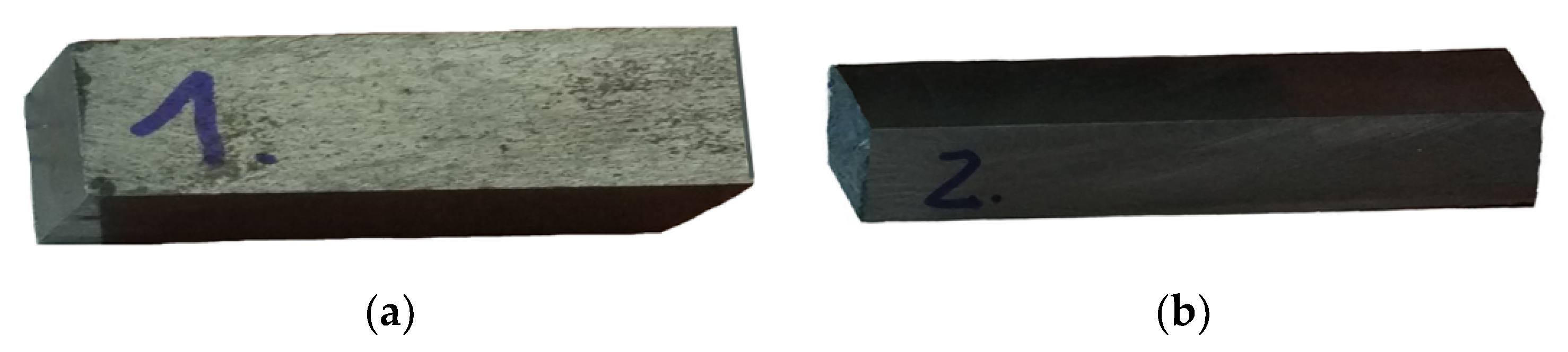
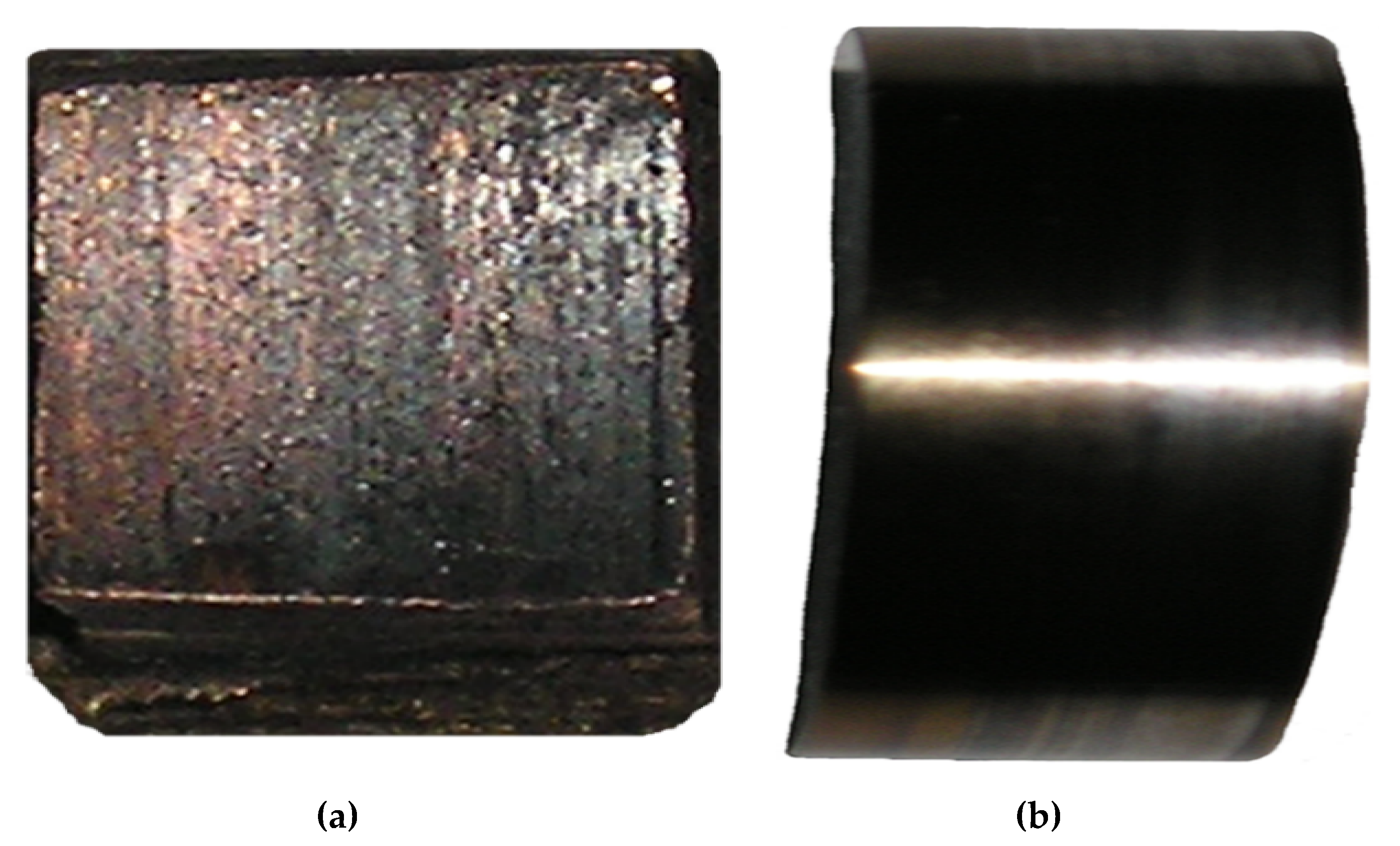
2.1. Materials

The study was focused on new self-lubricating antifriction composite materials based on powder nickel alloy EI929 with solid lubricant (see Table 1). EI929 is the standard known alloy that is used in industry. The chemical composition of EI929 is governed by the interstate standard [32]. A solid lubricant powder of calcium fluoride was added to the original mixture (see Table 1). CaF2 was chosen as an additive to the antifriction material because it is a solid lubricant that remains chemically stable in high-temperatures. This solid lubricant is effective at elevated and high temperatures and retains its properties up to 1573 K (1300 °C) [3,26,33].
The mechanical and tribological properties of the EI929-based composite on with solid lubricant CaF2 are described in Article [3]. As a result of hot isostatic pressing and heat treatment, the matrix structure of the studied powder alloy EI929-based compositions is a solid solution, highly concentrated and highly homogeneous alloy with the dispersed large numbers of intermetallics and carbides. Such a structure ensured the formation of high-level mechanical properties, which is an important factor in the operation of any material, especially composite. Mechanical properties of the examined materials are presented in Table 2.
The samples for mechanical tests were manufactured in standard sizes. Therefore, impact resistance test samples were 55 × 10 × 10 mm3 in size. Impact resistance was investigated using standard samples without an incision, because, test samples from powder materials are known to be made without an incision. Bending strength tests were carried out using standard samples with dimensions of 55 × 10 × 5 mm3. The bending test procedure included applying a load to the center of the sample, was placed on two supports. The distance between the supports was 40 mm. Exemplary samples for testing mechanical properties are shown in Figure 1.
The tested material was analyzed using a scanning electron microscope (SEM) before performing tribological tests. Analysis results are summarized in Figure 2 with a fracture view shown in Figure 2a. The solid lubricant CaF2 distribution in a material is shown in image (Figure 2b) of the cross section made on the metallographic specimen.
The picture provides an example of a sample structure with a 6% CaF2 content. In the analyzed area, gray secretions of CaF2 lubrication were shown against the background of the light matrix of EI929 material. An even distribution of solid CaF2 grease in the composite was demonstrated, which was a consequence of the manufacturing technology used. This is an important factor for work with the material without smooth lubrication. Calcium fluoride, evenly distributed throughout the entire volume of the composite, surrounds the friction surface and participates in the formation of a friction film.

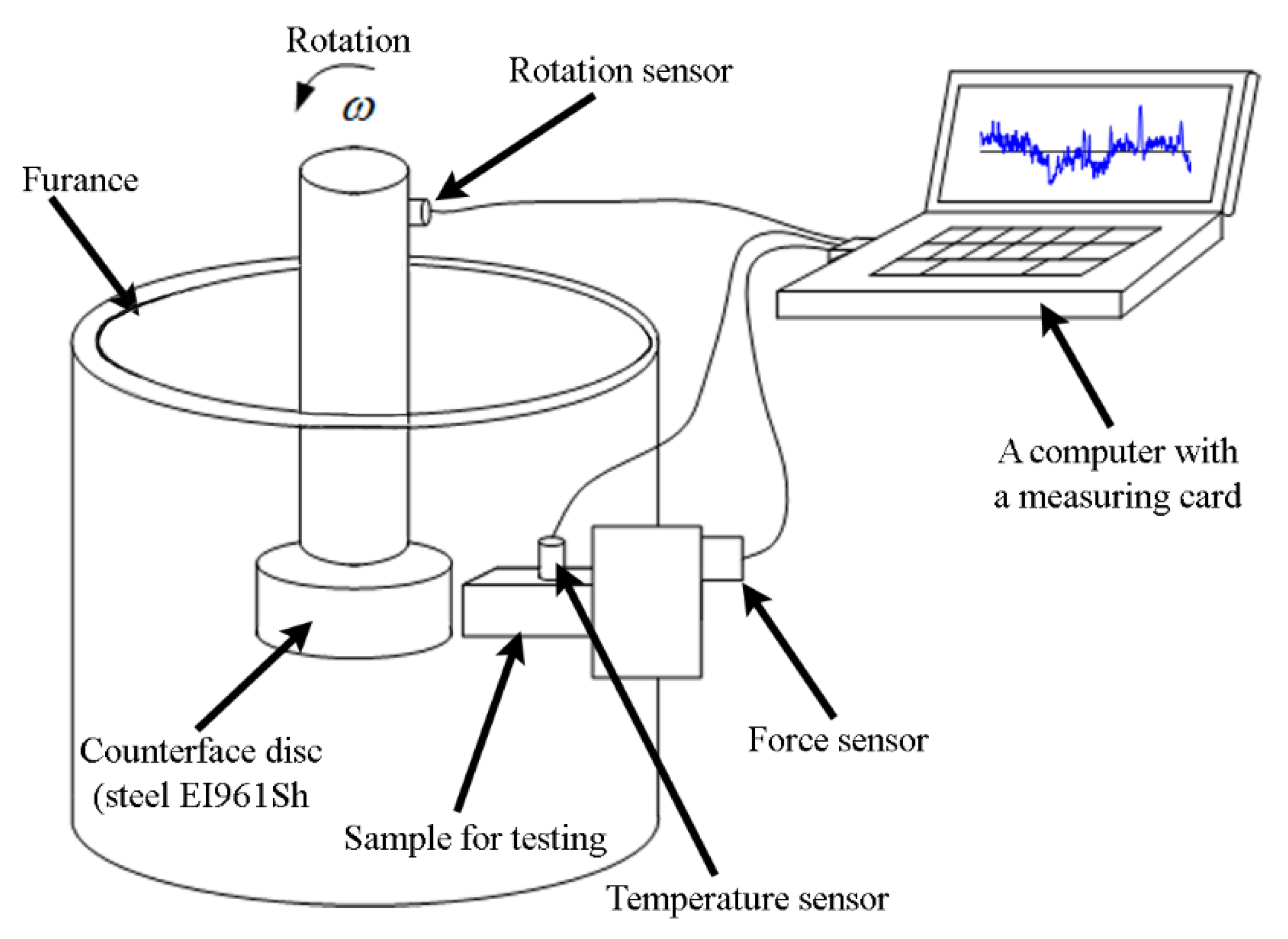
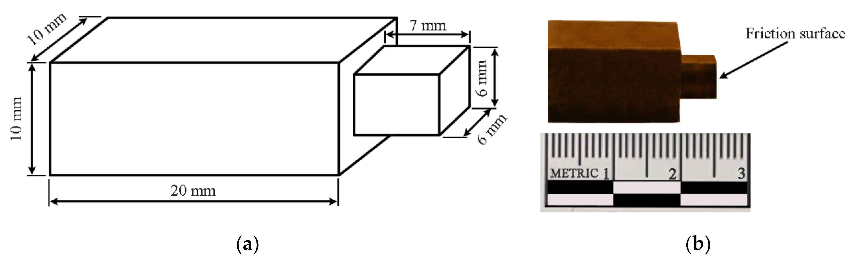
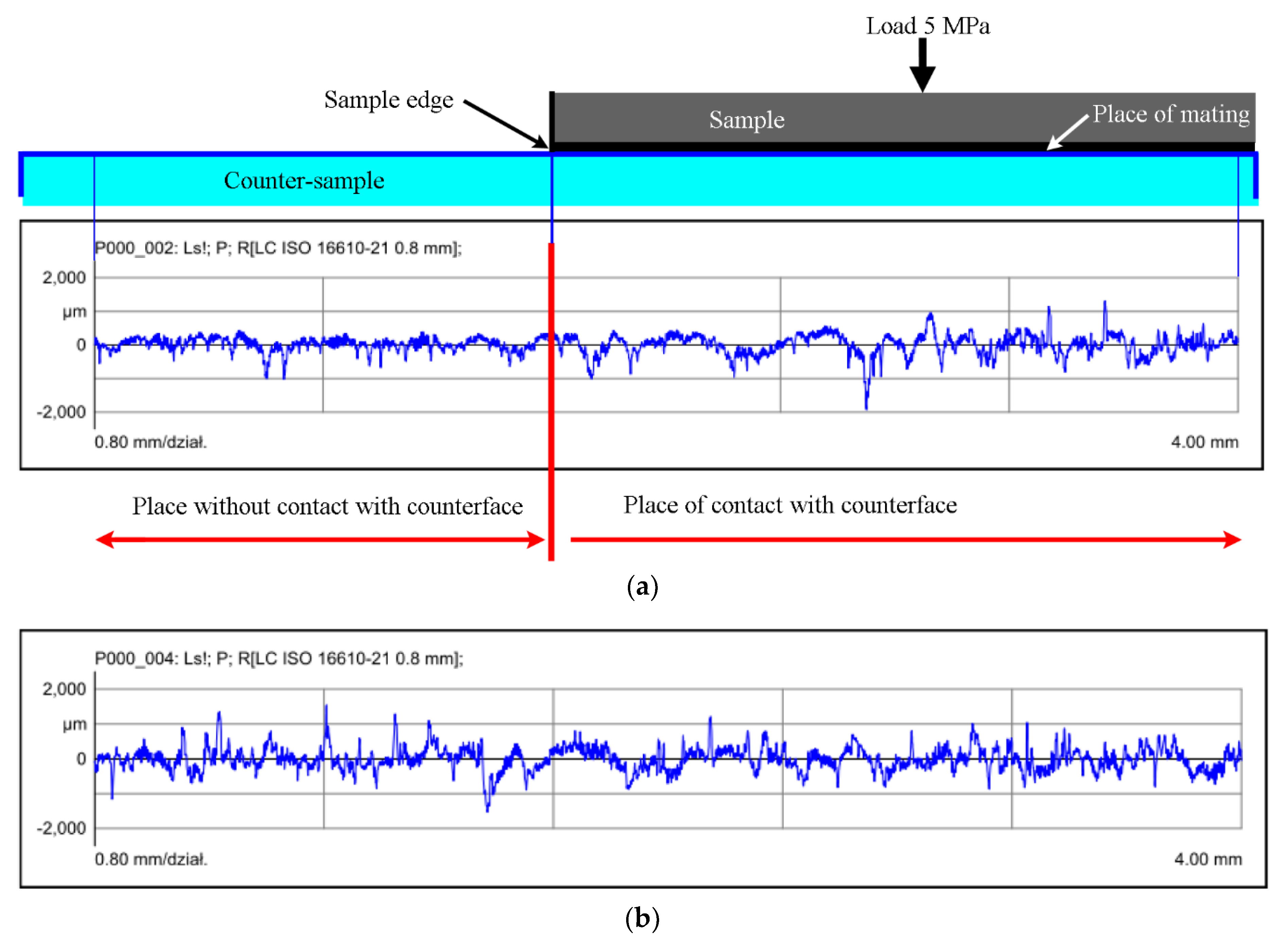
2.2. Tribological Tests

Tribological tests were performed on a VMT-1 friction testing machine. The experiments were performed at pressure P = 5.0 MPa, temperature T = 873–1473 K, counterface disc rotation speed V = 0.32 m/s. The work pressure for the material studied was 5.0 MPa. The scheme of the station is shown in Figure 3. A scheme of the VMT-1 friction testing for of the composite material EI929 + CaF2.
Increasing the pressure leads to an increase in temperature on the surfaces under friction. But in our experiments, the analysis of the interaction of the studied material with oxygen was carried out at temperatures from 873 to 1273 K. These temperatures were higher than the temperatures that occur when the pressure increases to 5.0 MPa.
Samples for tribological tests are presented in Figure 4. The friction surface of the composites was 36.0 mm2. Therefore, we only state the pressure at which the friction tests were performed. Post-test samples after tests are shown in Figure 5. Counterface is made of stainless high-temperature, high-alloyed chrome-nickel steel EI961Sh. The EI961Sh steel corresponded to the material of the real shafts in the high-temperature friction units. The chemical composition of this steel is summarized in Table 3.
In the test, the friction track was 5.0 km in the tribological testing process. After that, the measurement of linear wear was performed. Samples were cut from a blank obtained by hot isostatic pressing (see Figure 4). Next, they were ground as it is done with real parts before installation in the friction units. These operations were performed to maximize compliance with actual conditions.
Aspects of the antifriction behavior of the surface layer were microscopically analyzed. SEM microscopic observations included: testing of friction surfaces and testing cross-sections of samples showing the structure of the friction layer and the material under its surface. The study also included presentation of the distribution of elements in the cross-section of the friction layer. These tests were carried out on a Hitachi TM-3000 scanning microscope (Hitachi, Tokyo, Japan) equipped with an EDS attachment.
The number of oxides was determined by the thermodynamic analysis method and compared with the experimental results.

3. Results and Discussion

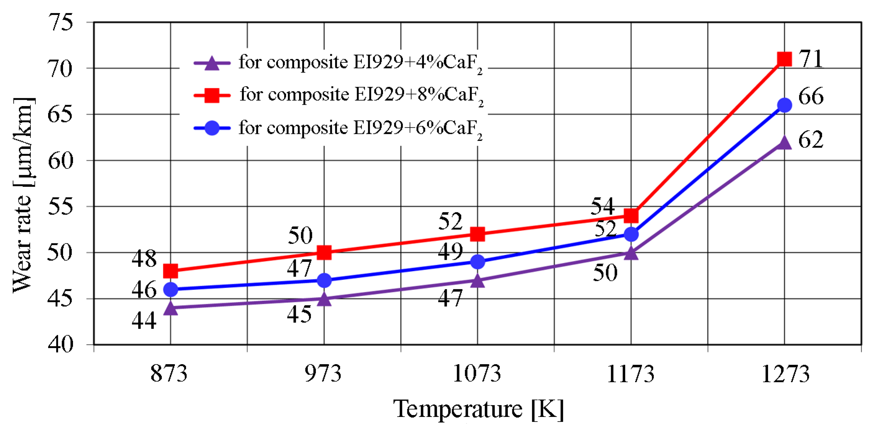
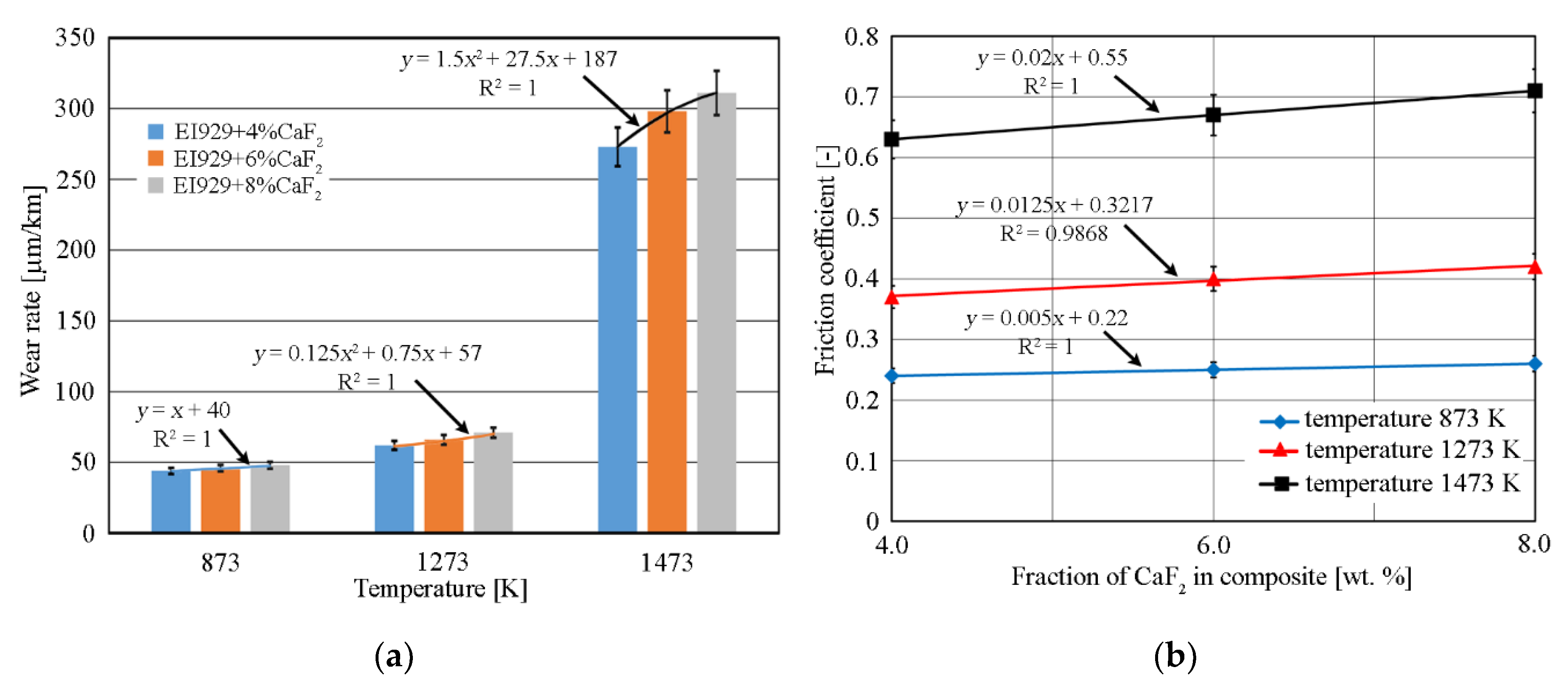
3.1. High-Temperature Tribological Properties

The film on the contact surfaces begins to form from the very beginning of the high-temperature tribological tests. The intensity of its formation increases with increasing temperature. This was due to intensification of the oxidative processes of pure elements, their carbides and intermetallics. A dense friction film 5 μm thick, was formed over the entire contact surface after about 1 km of the friction track. The film prevents further penetration of oxygen into the composite and its oxidation at high temperatures. The external effects on the new materials friction process and their interaction during tribological activity cause complex synergetic processes in surface layers, which develop due to the system being open and energy flow from the outside. This results in a multivariant synergetic system characterized by nonlinear internal processes, specific peaking modes [9,34,35], and, as a consequence, at least two stable states in direct relationship with temperature conditions. The formation of such a multivariant synergetic system led to multiple-element dissipative structures (secondary structures) with multivariant and ambiguous behavior, whose antifriction properties change substantially depending not only on material composition, but also on the intensity of external effects such as temperature [9,36].
The friction films as dissipative structures are complex, dynamically changing formations on the surfaces of the composite and the counterface, developed by the bifurcation mechanism. With their self-organization, these structures tend to deviate to one or the other attractor; in other words, they stay in two comparatively long-term states of the system. Because of this duality, the films had different compositions and behaved in two different ways, directly depending on the type and intensity of energy coming from outside: either as an antifriction lubricating layer promoting excellent tribological properties and stabilizing the friction pair or as a coarse abrasive layer leading to intensive wear of the friction pair. Therefore, the analysis of the material’s oxidation processes was carried out under temperatures where material demonstrates high antifriction properties and at a temperature leading to friction coefficient increase and intense wear (see Table 4). Interestingly [2], the wear rate can be determined by different methods. Of the known methods for assessing the wear, the most common are weight and linear, as the simplest and most reliable [37]. In our studies, linear wear was measured, which was a change in the sample’s linear dimensions per kilometer of the friction track.
Therefore, the linear wear of the studied material was determined in micrometers per kilometer of the friction track. This was the change in the linear dimension of the sample (sample height) per 1 km of the friction track. As Table 4 shows, the composite demonstrates high functional properties at temperatures up to 1273 K. The increase of temperature to 1473 K has resulted in a sharp decrease in antifriction properties.
The performance temperature conditions for the friction pair turned out to be decisive for forming secondary film structures with various properties (bifurcation phenomena) in states far from equilibrium and led to a relatively long-term mode of the system (attractor). Data on the solid oxide concentration was obtained from the composite’s surface at temperatures 1073 and 1173 K based on thermodynamic formula according to dependence:
Δ G o = Δ H o ( T ) T Δ S o ( T ) ,
where ΔGo(T) − Gibbs energy change; ΔHo(T) − enthalpy change; ΔSo(T) − entropy change at temperature T.
Due its complexity, the system was divided into multiple subsystems wherein the matter exchange is physically possible, and the equilibrium state can be determined. That approach allowed simulating chemical processes with greater accuracy. ASTRA.4 software was used to conduct calculations.
In the friction process, the studied composite was tested in contact with the counterface made of stainless cast steel EI961Sh. Obviously, the mass transfer effect takes place during friction process [9]. The mass transfer effect was the mutual transfer of the contact pair’s chemical elements to the surfaces of each other.
Except for pure iron, in the EI961Sh steel there are other phases containing iron, as well as alloying elements phases, such as carbides and intermetallics. Therefore, the analysis of the interaction the counterface structural components with the air was also performed using the thermodynamic analysis method. The counterface material consists of the structural components that are similar to the components of the studied composite. These are carbides of chromium, titanium, molybdenum, vanadium, tungsten and complex chromium carbides containing iron [9]. Because iron is the main element in EI961Sh, the thermodynamic analysis of the interaction of iron with oxygen was also performed. The thermodynamic analysis of the interaction of the main components with the air was carried out in the temperature interval 600–1300 K at intervals of 200 K. The ratio of the components to air was varied as follows: variant α = 50:50 wt %; variant β = 10:90 wt %; variant γ = 90:10 wt %. Such variations allow observing the development of oxidation processes with excess and lack of oxygen.
It is known the FeO, Fe2O3 and, Fe3O4 oxides exist in the system [38,39]. The intensive carbide oxidation occurs at temperatures above 1273 K and depends on the carbon amount in steel [40]. Oxidation resistance increases at the carbon amount growth. The oxidation products contain chromium, iron, molybdenum, tungsten and vanadium oxides. The authors state that the pure iron oxidation is accompanied by the formation of Fe2O3 oxides (up to 473 K), then Fe3O4 (at 673 K) and FeO (after 843 K).
The counterface material, EI961Sh steel, contains small amounts of manganese and silicone. We can assume the oxygen dissolution in Mn and Si compounds will lead to the appearance of MnO, Mn2O3, SiO2 oxides in small numbers at a high temperature oxidation. The manganese and silicon oxides concentration is much lower than the amount of chromium, titanium, iron, nickel and others oxides. Therefore, the manganese and silicon oxides number will probably have no significant effect on the total amount of oxides.
Iron is oxidized in several stages. In the Fe−O system, Fe2O3 oxides were formed at 473 K and coexist with pure iron in a case of oxygen absence (variant γ). At variant α, Fe2O3 oxides were transformed to Fe3O4 oxides at 673 K, and Fe2O3 coexists with Fe3O4 oxides. Above 673 K, there were only Fe3O4 oxides at variant α. In the case of excess oxygen (variant β) the Fe3O4 oxides were transformed into the FeO oxides and they coexist in the interval of 673–843 K. Only the FeO oxides exist at temperatures above 843 K at the oxygen excess [41,42]. Oxidation products contain free iron on the friction surface due to large amounts of iron in the steel counterface. Table 5 shows concentration of solid oxides after tribological tests at 1073 and 1173 K.
Table 5 data shows the temperature rise to 1173 K and above, leading to intensification of the oxidation processes. Among the solid oxides, the amount of iron, chromium, titanium and other element oxides is significantly increased in the friction film. At temperature conditions, the friction film becomes an abrasive substance and cannot provide high antifriction properties. Such concentration of solid oxides on the surface (see Table 5) is characteristic both for the researched antifriction composite and for a counterface as a result of the mass transfer effect at the friction process.
From the analysis of results, it follows that formation of the composite’s surface film was accompanied by the formation of NiO, FeO, Cr2O3, V2O5, TiO2, Co3O4, CaO, CeO2, B2O3 and Al2O3 solid oxides. In addition, MoO2, WO2, V4O10, CO, CO2, F2 molecules were present at the vapor phase at 1073–1173 K. Oxidation products contain free nickel and iron, which was due to their increased concentration compared to other elements.
Phase composition of the material and counterface, the strengthening phase number and the formed oxidation products make it possible to conclude that the oxides of alloying elements were formed from the corresponding carbides and intermetallics, both from the composite material and counterface. The total amount of alloying elements, carbides and intermetallics is proportional to their content in the original material composition, were described in works [3,9]. Subsequently, this causes formation of the oxides in proportional amount. References include information about impurities located on the boundaries of particles that form a diffusion barrier to the oxygen penetrating into the powder particles, and protect nickel against oxidation [40,43,44,45]. Thus, the more oxides of other chemical elements were formed, the slower was nickel oxidation. The alloying oxide elements envelop EI929 particles in the surface layer and hinder the penetration of oxygen into the alloy.
This phenomenon was observed by visual inspection of samples after tribological tests and confirmed by high and stable antifriction properties at high temperatures. Thereby oxides “build” a barrier against nickel oxidation and the NiO amount does not increase, as it was shown in [46,47,48]. The oxide composition formed with calcium fluoride determines the tribological characteristics of the researched antifriction composite with an average value of solid lubricant, depending on temperature (see Figure 6).
Analyzing parameters of experimental tests, high wear resistance (low wear rate, J) was observed at friction in the wide temperature interval 873–1173 K. This was due to the balance between the formation and wear of oxide-fluoride compounds, which form the antifriction film and provide a minimum of wear intensity for these tribo-thermal conditions. The minimum wear was observed due to the optimal combination of oxide and fluoride phases, their properties and composition. Therefore, a conclusion can be made that high tribological properties were caused by the formation of dense oxide-fluoride films in the interval 873–1173 K. The wear ratio of films coincides with their restoring speed at such working conditions. An increase of the material wear intensity was observed at temperatures above 1173 K (see Figure 6).
In this case, the balance between the film formation and wear was broken. Intense oxidation leads to the appearance of the Cr2O3, FeO, V2O5, TiO2 and other solid oxides in large numbers (see Table 5). Calcium fluoride cannot perform lubrication functions in such conditions. Thus, the catastrophic wear occurs, when the friction film’s antifriction properties become abrasive due to intense oxidation. Thus, the qualitative and quantitative composition on oxides was obtained in the antifriction composite friction film under different temperature conditions.
The experimental result analysis showed that wear resistance was determined by the ability of material to form thin and dense oxide phases with solid lubricant CaF2 on the working surfaces at high temperature friction in the air. Formation of the optimal protective films can be forecasted using the thermodynamic method, recognizing the qualitative and quantitative composition of alloying elements in the material. The thermodynamic analysis used allows obtaining reliable information and can be used to study the interaction of self-lubricating antifriction composites with the air at different temperatures. The optimum concentration of oxide phases in combination with solid lubricant will ensure the formation of such friction films. This approach allows choosing the temperature conditions for composite antifriction materials. Therefore, the rational working temperature interval was 973–1173 K for the studied composite EI929 + (4–8)% CaF2, when the material demonstrates the highest functional properties. The maximum allowable temperature was 1273 K, above which the functional properties were greatly reduced (see Table 4, Figure 6).
Features of the friction process of the nickel-based composite antifriction materials at high temperatures (see Figure 7) confirm that the wear resistance increases dramatically above 1173 K. As shown in Figure 7a, the increase was more than threefold at 1273 K. The CaF2 content percentage becomes nonlinear. Based on the trend of wear rate curves of the studied composite, it was shown that the material exhibits the highest functional properties in the range of 873–1173 K. Figure 7b shows the relationship between the coefficient of friction and the mass concentration of solid lubricant CaF2 in the analyzed samples obtained after friction tests on track about 5 km at a speed of 0.32 m/s and a clamping force of 180 N. The presented results indicate the approximately linear nature of this relationship. The relationship between the coefficient of friction and the mass concentration with solid lubricant CaF2 was linear for all composite materials tested. The linear harmony was 98.7% only 1273 K while in other cases it was 100%. The friction coefficient varies slightly in the range 873–1173 K and depends only on the number of oxides in the friction film. This confirms the optimal CaF2 content between 4.0 wt %–8.0 wt % in the composite, when a balance takes place between the wear of the antifriction film and the formation of its new sections at temperatures up to 1273 K (see Figure 7b). For 1473 K, the increase in the friction coefficient was significant, since the intensity of the oxidation processes increases sharply, as described above. At temperatures above 1273 K, a solid lubricant, regardless of its quantity, can no longer provide stable operation of the friction pair since an intense friction surface oxidation occurs. As a result, the friction coefficient increases, and the composite begins to act as abrasive material (see Figure 7b).

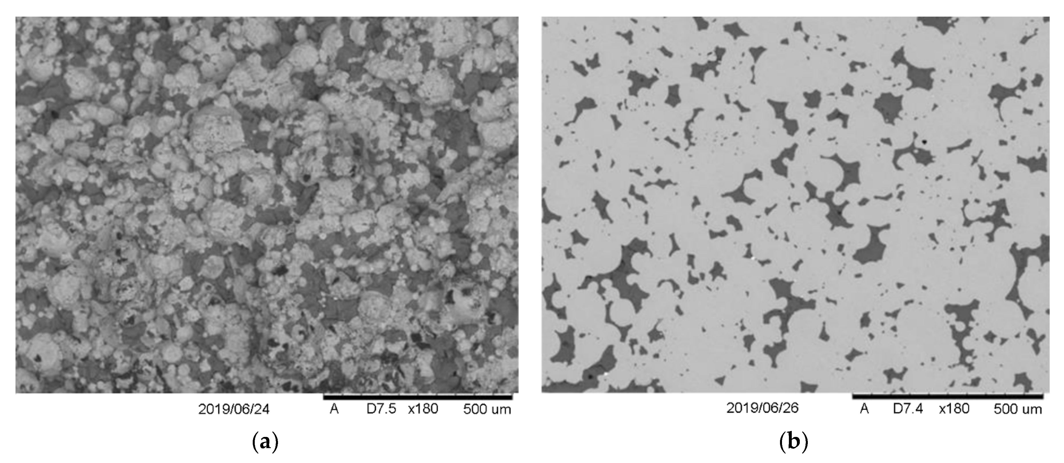
3.2. Microstructure Changes of the Composite Friction Surface

Microscopic analysis consisted of studying the CaF2 solid lubricant distribution before starting tribological tests. As shown in Figure 8, CaF2 distribution reflects the powder particles geometry of the composite, which was obtained from the sprayed (spherical) powders of the nickel alloy EI929. CaF2 particles were arranged around the spherical particles of EI929, as seen in Figure 8b. Such arrangement of CaF2 solid lubricant particles was a consequence of composite manufacturing technology (see Figure 8). The performed microscopic analysis of surfaces after tribological tests were carried out not only allows determining the oxide phases quantitative ratio in the friction film, but also studying the behavior of CaF2 solid lubricant at high temperatures.
General view of the friction surface in Figure 9 shows the friction process creates a characteristic band structure oriented along the friction direction. The friction of sample abrasion under pressure P = 5 MPa causes a gradual separation of the friction film. Separation of individual fragments of the layer was combined with their brittle cracking small fragments falling off the surface layer. At the same time, new fragments of the friction film were formed at these places. Thus, the friction film was constantly present on the contact surfaces and implements the self-lubrication mode at studied operating conditions. Surface characteristics indicate a high uniformity in the distribution of solid lubricant on the surface during tests carried out at 973–1173 K.
The finding confirm the presence on the friction surface of small zones, where lubricant “chambers” filled with CaF2 were formed, which was a consequence of plastic deformation of the material during friction. These areas were sources of the continued presence of CaF2 solid lubricant during friction. In these areas, the processes of material wear intensify with increasing temperature over time due to the appearance of deep scratches, fragmentation and the formation of craters (see Figure 10). It should be noted that the morphology of composite friction surfaces after wear tests at 873, 973, 1073 and 1173 K was identical and contributes to high tribological properties (see Table 4, Figure 6).
The friction process intensifies at the abrasion at 1173 K, and at increasing the temperature to 1273 K which leads to the loss of composite’ stability caused by the intensive oxidation of the entire friction surface.
As a result, the mechanical abrasive wear occurs. Then a mechanically mixed layer was formed with a thickness of approx. 3–5 μm. On this surface, a film with individual fragments, 1 to 2 μm thick was observed. In the abrasion process, at some point, small fragments of a strongly oxidized film break under friction forces. The moment immediately before a fragment of the material breaking off, which opens a “chamber” with CaF2 lubricant is shown in Figure 11. After breaking off, fragmented pieces of friction film that move in the contact zone, act as loose abrasives, contributing to abrasive wear and removal of mechanically mixed fragments of the layer (see Figure 11b).
Micro cutting, in which the oxide film layer is removed, also acts on the native material, increasing its wear and damage. The effects of plastic deformation appear on these surfaces, which look like elongated “flakes” of material flowing in the direction of deformation, which has been confirmed by research (see Figure 12a). Deformed layers of material adhere to each other due to the local adhesive forces. Initially the products of wear were formed on the surface. Then in some moment the products of wear and lubricant were closed under the surface of the formed “flake”. After that, the process was repeated again (see Figure 12b). Thus, the self-lubrication mechanism was realized.
As part of EDS tests, with the help of map analysis, elements were identified and their distribution in the area on and below the friction surface (see Figure 13). The distribution maps of the composite’s matrix elements: Ni, Cr, Co, Mo, Ti, F, Ca (Fe from counterface) and W were obtained. It was difficult to identify Ce and B due to their small number, and also, probably, elements with higher screen contents of cerium and boron.
The Figure 13 shows the uniform distribution of chemical elements that determines the uniform distribution of the corresponding oxides in the antifriction film. This ensures the formation of a homogeneous structure of the surface layer, which stabilizes the friction pair at high temperatures.
The analysis confirms the formation of the mechanically mixed layer on the friction surface with an increased content of elements such as oxygen O and iron Fe. Such layer consists of an antifriction lubricant at high friction temperatures. Anti-scoring films provide high wear resistance of the self-lubricating composite 973–1173 K due to the balance between the rate of their formation and wear (see Figure 6, Table 4).
The distribution of selected elements as a function of depth of the friction surface was illustrated by means of a linear EDS analysis (see Figure 14).
The tests were carried out at a depth of 5 μm below the surface, excluding surface interlocked products (see Figure 15). The analysis showed an increase in the number of oxide phases formed on the friction surface. An increase in the number of oxide phases was observed at a depth of up to about 2 μm, with their largest share on the friction surface. In the selected place, the presence of an increased amount of TiO2 in the surface layer was clearly indicated, although the presence of other oxides also occurs. This was due to the high affinity of chromium and titanium to oxygen.

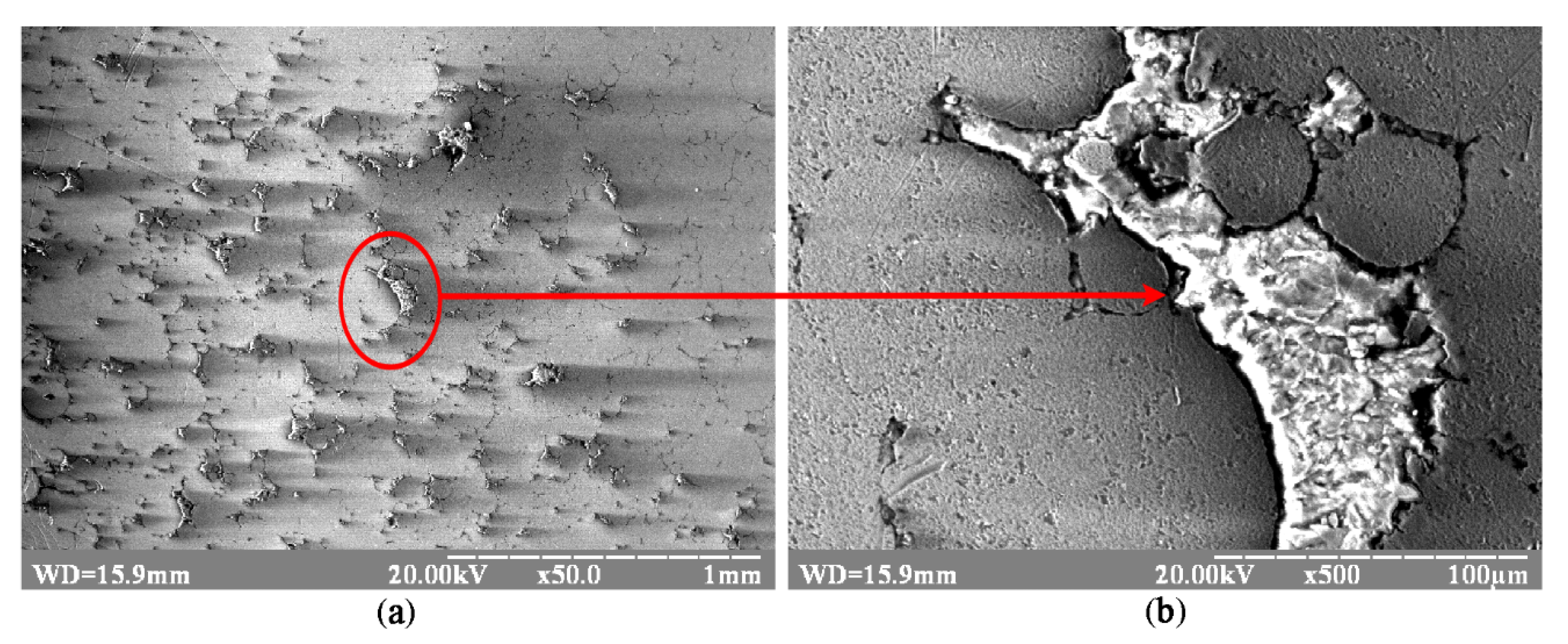
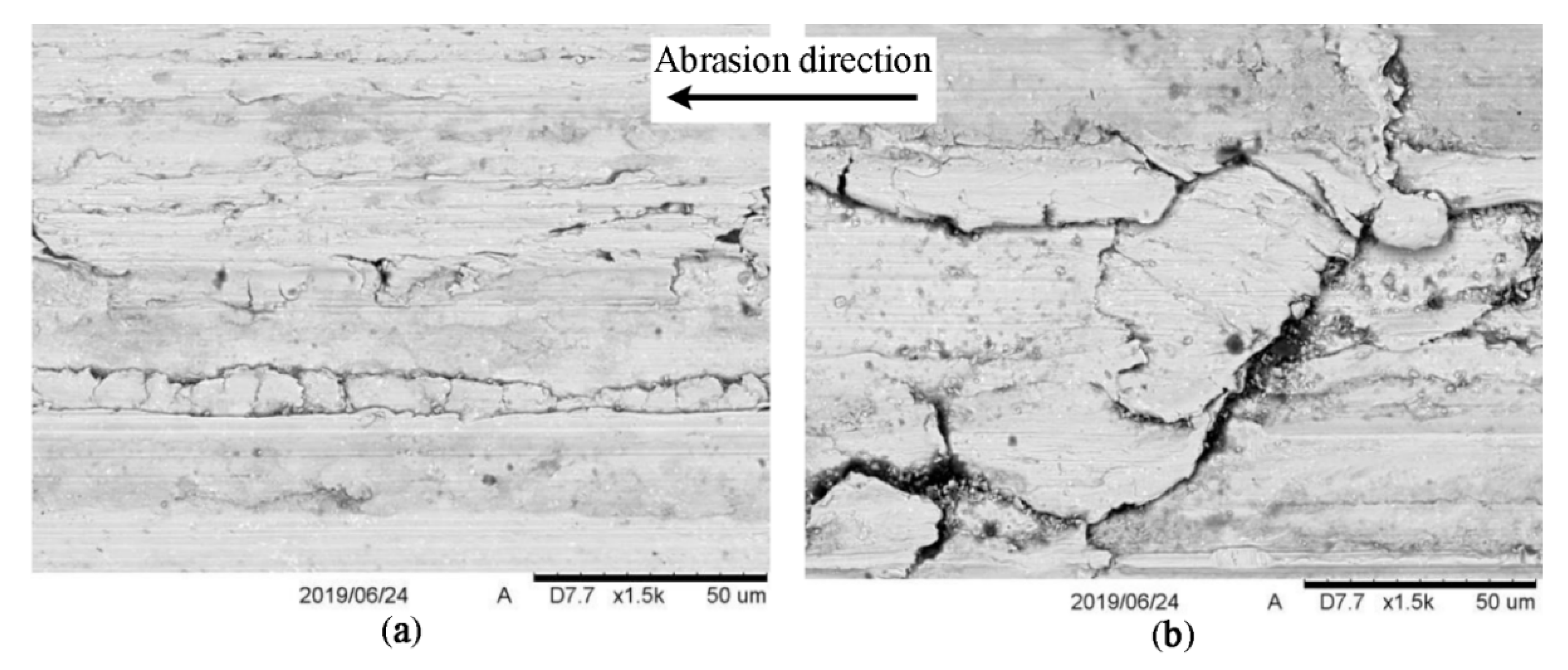
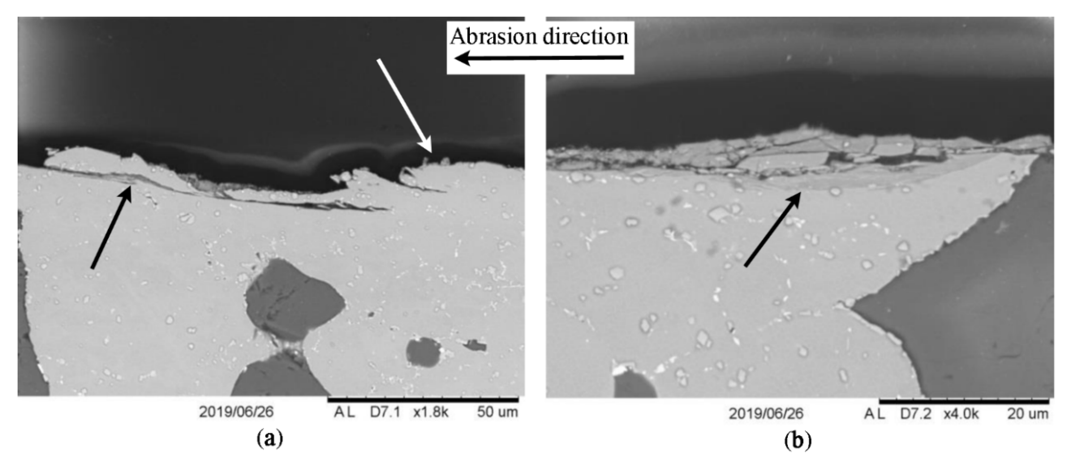
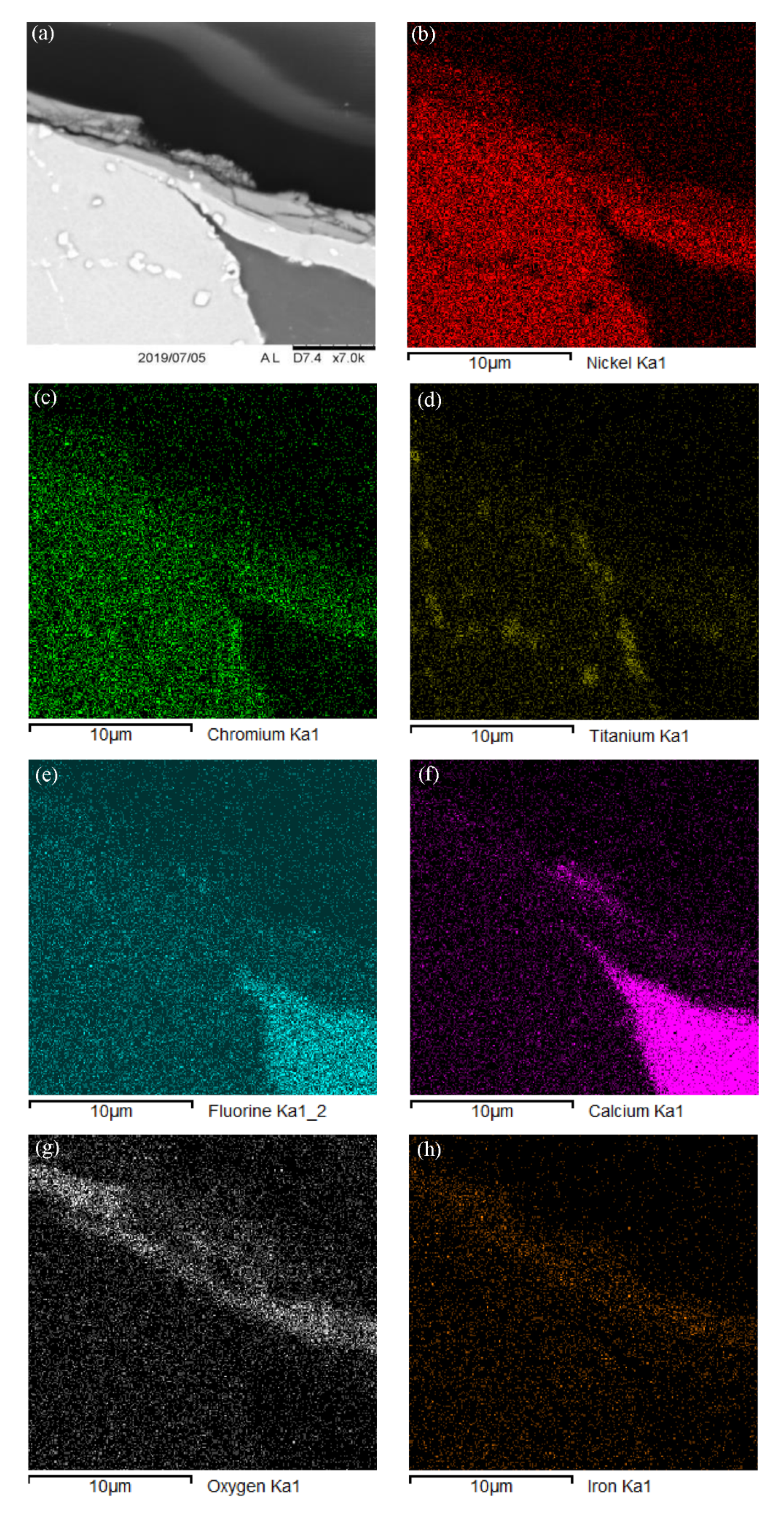
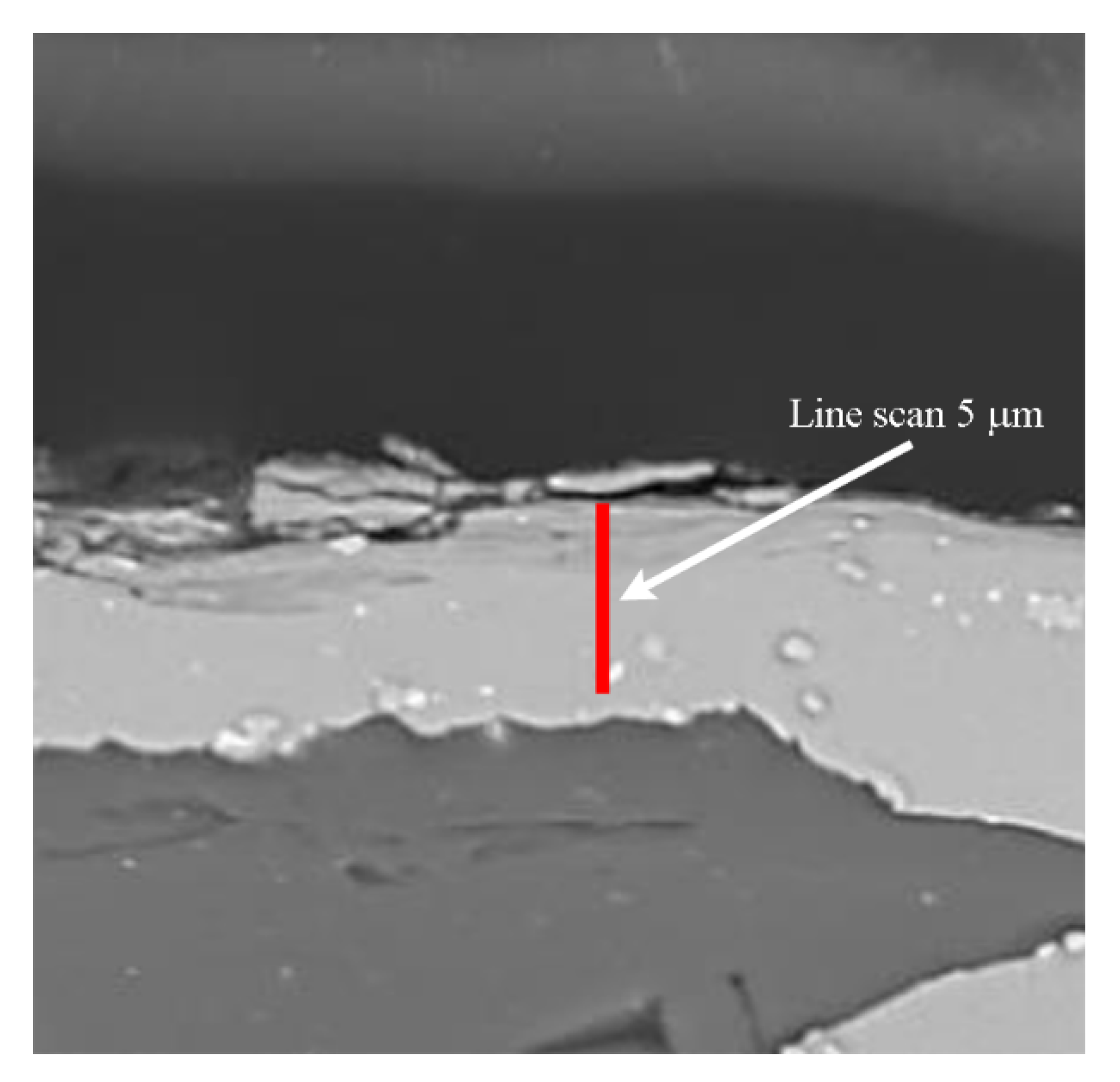
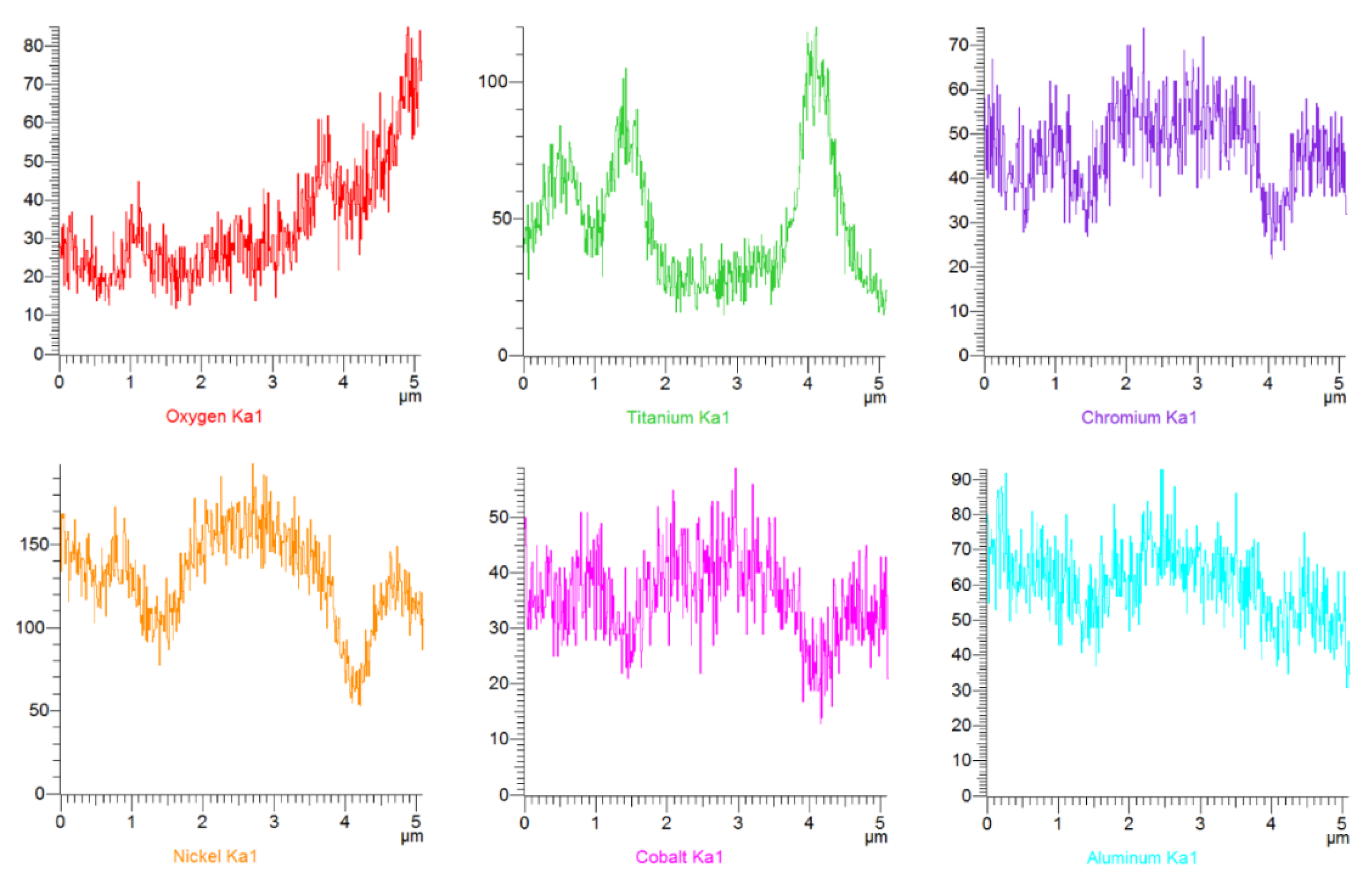
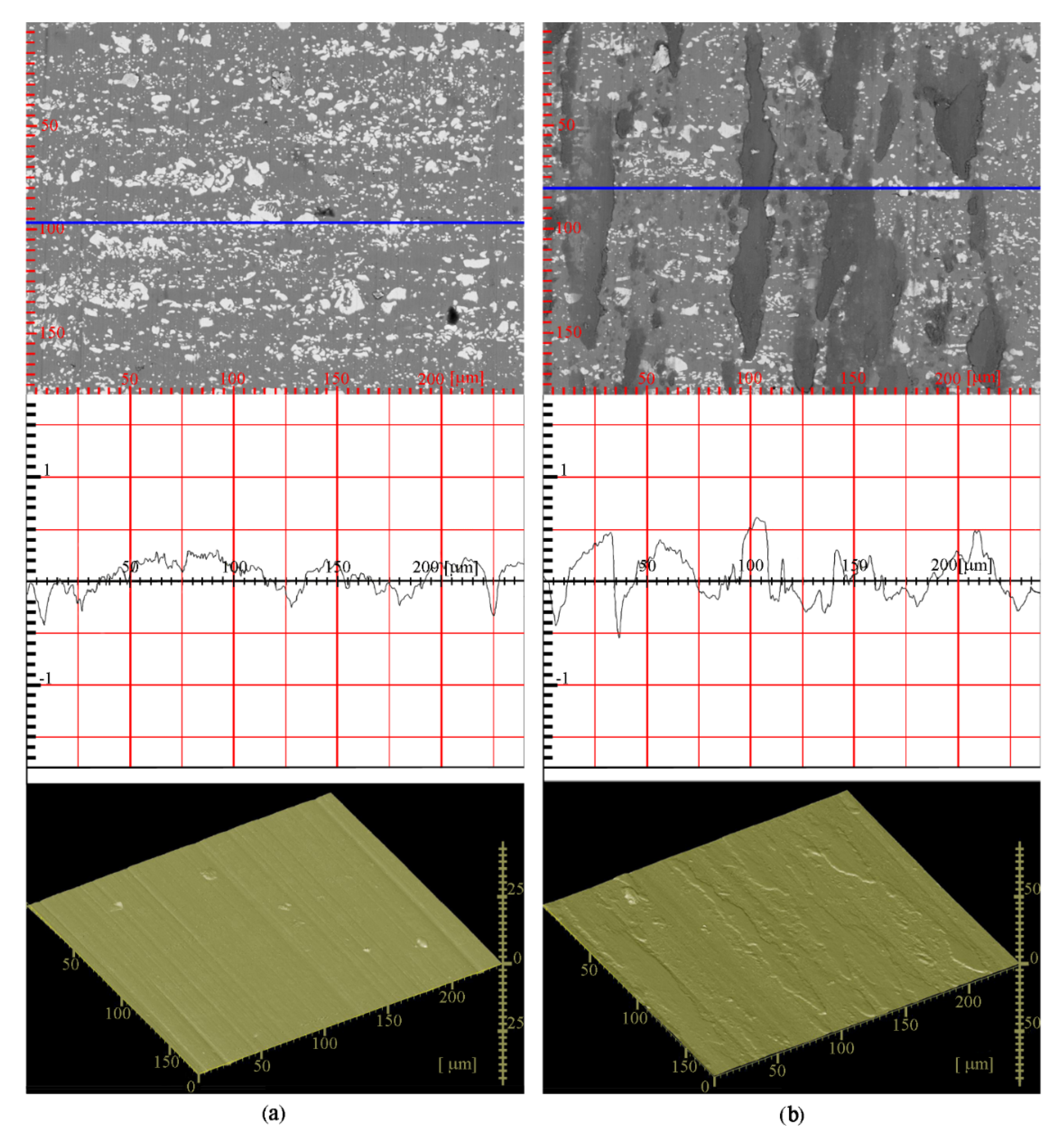
3.3. Analysis of Worn Surfaces

To illustrate the mutual influence of both members of the friction pair and determine the relationship between the sample and the counterface, surface roughness tests of the counter-sample were also carried out. These tests were very important in order to confirm the presence of an antifriction film on the contact surface, to monitor the change in its geometry and to determine its parameters. Surface roughness was analyzed with a MarSurf SD 26 profilometer (Mahr, Werl, Germany). Comparative measurements with visual surface assessment were also carried out using the 3D-Image Viewer system and the Hitachi TM-3000 electron microscope. Measurements on the profilometer were carried out on five measuring lines, each 4 mm long, taken in separate places for each sample, and on 20 measuring tracks 240 μm long for each of the five images obtained in the 3D image. In both cases, measurements were carried out along the measurement lines perpendicular to the abrasion direction. The results are presented in Figure 16 and Figure 17.
Figure 16 above presents the state of the counter-sample surface after friction, with an example of roughness determination. Figure 17 shows the surface view before and after the friction test, respectively.
The results in the form of the mean value from the measurements are presented in Table 6. The results clearly confirm the increase in the value of roughness parameters. Analysis of the surface roughness after the abrasion process clearly shows that a layer of lubricating film was created on the surface of the counter-sample. It appears as a banded structure along the abrasion line. This layer forms parameters characterizing roughness (see Table 6). The arithmetic mean deviation of the profile from the midline Ra increases by 37–42% after the abrasion and the height of the profile Rz was 18–21% higher relative to the surface before abrasion. Analysis of the surface roughness of the counter-sample at the point of contact with the sample edge did not confirm wear of the counter-sample, but only the increase in profile height due to the presence of a lubricating film layer. The differences between the methods result from the adopted measuring section Ir.
As it can be seen from Figure 17b, an antifriction film was present on the surface of the composite after tribological tests. This film covers the entire friction surface and contributes to the stable operation of the friction pair.
As shown in Table 6, the performed surface roughness tests showed an increase in average roughness (Ra) of approx. 39.5% after friction tests, which confirm the presence of the formed antifriction film on the material’s surface. Such film ensures the tribological properties high level and the studied composite stable work.
In conclusion, based on the surface roughness analysis after tribological tests and the studies of other authors [7,20,49], one can be tempted to assess the impact of friction on the functional properties of the composite based on EI929 nickel powder with solid CaF2 lubrication at high temperatures. The tested wear resistance of the self-lubricating composite in the temperature range of 873–1273 K shows specific effects in individual temperature ranges. After exceeding the temperature threshold (1200 K), it was noted that the friction film loses lubricity and acts as an abrasive. Abrasive surfaces of materials undergo some degradation. These mechanisms are summarized in Table 7.

4. Conclusions

The material science approach was used to describe the structural features of the friction films formation, their composition, the distribution of chemical elements inside them, and their influence on the functional properties of high-temperature nickel composites. Research of the friction mechanism of the antifriction composite material based on powder nickel alloy EI929 + (4–8)% CaF2 was carried out using the thermodynamic analysis of oxidation process at high temperatures, micro-structural studies by EDS, tribological and mechanical tests, measuring of roughness parameters.
It has been shown that the wear and friction mechanism was oxidative in nature. The formed oxide composition with calcium fluoride determines the tribological characteristics of the researched antifriction composite. Quantitative ratios of oxide phases were obtained for 1073 and 1173 K. Microscopic analysis confirmed the increase in the number of described oxide phases in the antifriction film, which corresponded to the content of each alloying element in the composite’s nickel matrix. An increase in the number of oxide phases was observed at a depth of about two micrometers. This phenomenon was observed by visual inspection of samples after tribological tests and confirmed by high and stable antifriction properties at high temperatures.
High tribological properties were observed during friction in the wide temperature interval 873–1173 K. This was due to the balance between the formation and wear of oxide-fluoride compounds, which form the antifriction film, and provide a minimum of wear intensity for these tribo-thermal conditions. The minimum wear was observed due to the optimal combination of oxide and fluoride phases, their properties and composition.
The high tribological properties were caused by the formation of dense oxide-fluoride films in the interval 873–1173 K. Such films wearing ratio coincides with their restoring speed during working conditions. An increase of the material wear intensity was observed at temperatures above 1173 K. In this case, the balance between the formation of film and wear was broken. Intense oxidation leads to the appearance of the Cr2O3, FeO, V2O5, TiO2 and a large number of other solid oxides. Calcium fluoride cannot perform lubrication functions in such conditions. Then the catastrophic wear occurs when the film’ antifriction properties become abrasive due to intense oxidation.
The formation of optimal antifriction protective films can be predicted by thermodynamic analysis when the combination of oxide phases and solid lubricant will provide high tribological characteristics at operating temperatures. Surface roughness tests after abrasion showed an increase in average roughness (Ra) of approx. 39.5% after tribological tests, which confirmed the presence of the formed antifriction film on the composite’s surface and allowed to determine its parameters.
Microscopic analysis data and EDS studies confirmed the oxidative nature of wear, which intensifies with increasing temperature. At 1273 K, the antifriction properties of the film were lost, leading to catastrophic wear.
The obtained results open up the possibility for creating composites with predefined properties by selecting initial powders with the appropriate combination of alloying elements as the basis of material.
Further research will be devoted to studying the nature of secondary structures on contact surfaces in order to obtain a broader nomenclature of anti-friction composites based on ferrous and non-ferrous metals in various operating temperatures.

Author Contributions

Methodology, investigation, data curation, writing—review & editing, A.K.; conceptualization, methodology, investigation, formal analysis, writing—original draft, validation, T.R.; resources, investigation, formal analysis, O.G.; investigation, software, visualization, project administration, I.V.; investigation, software, visualization, project administration, M.B.; software, visualization, formal analysis, D.P.; formal analysis, project administration, funding acquisition, P.Z.; conceptualization, methodology, validation, writing—original draft, writing—review & editing, supervision, K.J. All authors have read and agreed to the published version of the manuscript.

Funding

This research received no external funding.

Conflicts of Interest

The authors declare that they have no known competing financial interests or personal relationships that could have influenced the work reported in this study.

References

  1. Li, J.L.; Xiong, D.S. Tribological properties of nickel-based self-lubricating composite at elevated temperature and counterface material selection. Wear 2008, 265, 533–539. [Google Scholar] [CrossRef]
  2. Ezugwu, E.O. High speed machining of aero-engine alloys. J. Braz. Soc. Mech. Sci. 2004, 26, 1–11. [Google Scholar] [CrossRef] [Green Version]
  3. Kostornow, A.G. Tribotechnical Materials Science; Publishing house Knowledge: Lugansk, Ukraine, 2012. (In Russian) [Google Scholar]
  4. Jamroziak, K.; Roik, T. Structure and properties of the new antifriction composite materials for high-temperature friction units. In Lecture Notes in Mechanical Engineering; Abdel, M.W., Ed.; Springer: Singapore, 2019. [Google Scholar] [CrossRef]
  5. Ulutan, D.; Ozel, T. Machining induced surface integrity in titanium and nickel alloys: A Review. Int. J. Mach. Tools Manuf. 2011, 51, 250–280. [Google Scholar] [CrossRef]
  6. Tan, Z.H.; Wang, X.G.; Du, Y.L.; Duan, T.F.; Yang, Y.H.; Liu, J.L.; Liu, J.D.; Yang, L.; Li, J.G.; Zhou, Y.Z.; et al. Temperature dependence on tensile deformation mechanisms in a novel Nickel-based single crystal superalloy. Mater. Sci. Eng. A Struct. 2020, 776, 138997. [Google Scholar] [CrossRef]
  7. Varga, M.; Leroch, S.; Rojacz, H.; Rodríguez Ripoll, M. Study of wear mechanisms at high temperature scratch testing. Wear 2017, 388–389, 112–118. [Google Scholar] [CrossRef]
  8. Cui, G.; Liu, Y.; Gao, G.; Liu, H.; Kou, Z. Microstructure and high-temperature wear performance of FeCr matrix self-lubricating composites from room temperature to 800 °C. Materials 2020, 51, 51. [Google Scholar] [CrossRef] [Green Version]
  9. Roik, T.A.; Gavrish, A.P.; Krichok, P.A.; Vitsyuk, Y.Y. Effect of secondary structures on the functional properties of high-speed sintered bearings for printing machines. Powder Metall. Met. Ceram. 2015, 54, 119–127. [Google Scholar] [CrossRef]
  10. Kostornov, A.G.; Fushchich, O.I.; Chevychelova, T.M.; Simeonova, Y.M.; Kostenko, A.D. Friction, wear, and targeted synthesis of rubbing surfaces of self-lubricating composites. Powder Metall. Met. Ceram. 2007, 46, 111–117. [Google Scholar] [CrossRef]
  11. Cheng, J.; Qiao, Z.; Yin, B.; Hao, J.; Yang, J.; Liu, W. High temperature tribological behaviors of (WAl)C–Co ceramic composites with the additions of fluoride solid lubricants. Mater. Chem. Phys. 2015, 163, 262–271. [Google Scholar] [CrossRef]
  12. Stone, D.; Liu, J.; Singh, D.P.; Muratore, C.; Voevodin, A.A.; Mishra, S.; Rebholz, C.; Ge, Q.; Aouadi, S.M. Layered atomic structures of double oxides for low shear strength at high temperatures. Scripta Mater. 2010, 62, 735–738. [Google Scholar] [CrossRef]
  13. Roik, T.A.; Shevchuk, Y.F. Development of predictable secondary structures in materials for high-temperature bearings. Powder Metall. Met. Ceram. 2006, 45, 531–539. [Google Scholar] [CrossRef]
  14. Yang, X.; Wang, Z.; Song, P.; Cheng, J.; Gu, J.; Ma, T. Dry sliding wear behavior of Al2O3-TiC ceramic composites added with solid lubricant CaF2 by cold pressing and sintering. Tribol. Trans. 2014, 58, 231–239. [Google Scholar] [CrossRef]
  15. Torres, H.; Rodríguez Ripoll, M.; Prakash, B. Tribological behaviour of self-lubricating materials at high temperatures. Int. Mater. Rev. 2018, 63, 309–340. [Google Scholar] [CrossRef]
  16. Cui, G.; Li, H.; Gao, G.; Kou, Z. Design and high-temperature tribological properties of CoCrW with rare earth fluoride composites. J. Mater. Res. Technol. 2020. [Google Scholar] [CrossRef]
  17. Kwon, S.; Cho, S.-H.; Nersisyan, H.H.; Lee, J.; Kang, J.; Lee, J.-H. High-temperature stability of YSZ and MSZ ceramic materials in CaF2–MgF2–MgO molten salt system. J. Am. Ceram. Soc. 2017, 101, 2074–2083. [Google Scholar] [CrossRef]
  18. Kotkowiak, M.; Piasecki, A.; Kulka, M. The influence of solid lubricant on tribological properties of sintered Ni–20%CaF2 composite material. Ceram. Int. 2019, 45, 17103–17113. [Google Scholar] [CrossRef]
  19. Gajrani, K.K.; Suvin, P.S.; Kailas, S.V.; Sankar, M.R. Thermal, rheological, wettability and hard machining performance of MoS2 and CaF2 based minimum quantity hybrid nano-green cutting fluids. J. Mater. Process. Tech. 2019, 266, 125–139. [Google Scholar] [CrossRef]
  20. Zhen, J.; Li, F.; Zhu, S.; Ma, J.; Qiao, Z.; Liu, W.; Yang, J. Friction and wear behavior of nickel-alloy-based high temperature self-lubricating composites against Si3N4 and Inconel 718. Tribol. Int. 2014, 75, 1–9. [Google Scholar] [CrossRef]
  21. Cheng, J.; Zhen, J.; Zhu, S.; Yang, J.; Ma, J.; Li, W.; Liu, W. Friction and wear behavior of Ni-based solid-lubricating composites at high temperature in a vacuum environment. Mater. Des. 2017, 122, 405–413. [Google Scholar] [CrossRef]
  22. Wu, G.; Xu, C.; Xiao, G.; Yi, M.; Chen, Z. Structure design of Al2O3/TiC/CaF2 multicomponent gradient self-lubricating ceramic composite and its tribological behaviors. Ceram. Int. 2018, 44, 5550–5563. [Google Scholar] [CrossRef]
  23. Yang, X.; Cheng, J.; Song, P.; Wang, S.; Yang, L.; Wang, Y.; Mao, K. Wear behavior of cold pressed and sintered Al2O3/TiC/CaF2-Al2O3/TiC laminated ceramic composite. Acta Metall. Sin. Engl. 2013, 26, 157–166. [Google Scholar] [CrossRef] [Green Version]
  24. Chen, Z.; Guo, N.; Ji, L.; Xu, C. Synthesis of CaF2 nanoparticles coated by SiO2 for improved Al2O3/TiC self-lubricating ceramic composites. Nanomaterials 2019, 9, 1522. [Google Scholar] [CrossRef] [PubMed] [Green Version]
  25. Grigoriev, S.N.; Fedorov, S.V.; Hamdy, K. Materials, properties, manufacturing methods and cutting performance of innovative ceramic cutting tools—A review. Manuf. Rev. 2019, 6, 1–27. [Google Scholar] [CrossRef] [Green Version]
  26. Zhu, S.; Cheng, J.; Qiao, Z.; Yang, J. High temperature solid-lubricating materials: A review. Tribol. Int. 2019, 133, 206–223. [Google Scholar] [CrossRef]
  27. Zuomin, L.; Childs, T.H.C. The study of wear characteristics of sintered high speed steels containing CaF2, MnS and TiC additives at elevated temperature. Wear 2004, 257, 435–440. [Google Scholar] [CrossRef]
  28. Kotkowiak, M.; Pisasecki, A.; Kukula, M. Laser alloying of bearing steel with boron and self-lubricating addition. Arch. Mech. Technol. Mater. 2016, 36, 7–11. [Google Scholar] [CrossRef] [Green Version]
  29. Zhang, X.; Cheng, J.; Niu, M.; Tan, H.; Liu, W.; Yang, J. Microstructure and high temperature tribological behavior of Fe3Al–Ba0.25 Sr0.75 SO4 self-lubricating composites. Tribol. Int. 2016, 101, 81–87. [Google Scholar] [CrossRef]
  30. Sadrabadi, P.; Eisenlohr, P.; Wehrhan, G.; Stäblein, J.; Parthier, L.; Blum, W. Evolution of dislocation structure and deformation resistance in creep exemplified on single crystals of CaF2. Mater. Sci. Eng. A Struct. 2009, 510–511, 46–50. [Google Scholar] [CrossRef]
  31. Sharma, S.M.; Anand, A. Friction and wear behaviour of Fe-Cu-C based self-lubricating material with CaF2 as solid lubricant. Ind. Lubr. Tribol. 2017, 69, 715–722. [Google Scholar] [CrossRef]
  32. GOST 5632-2014. Stainless Steels and Corrosion Resisting, Heat-Resisting and Creep Resisting Alloys; Grades, Interstate Council for Standardization, Metrology and Certification (ISC): Moscow, Russia, 2015. [Google Scholar]
  33. Jianxin, D.; Tongkun, C. Self-lubricating mechanisms via the in situ formed tribofilm of sintered ceramics with CaF2 additions when sliding against hardened steel. Int. J. Refract. Met. Hard Mater. 2007, 25, 189–197. [Google Scholar] [CrossRef]
  34. Gray, P.; Scott, S.K. Chemical Oscillations and Instabilities: Non-Linear Chemical Kinetics; Clarendon Press: Oxford, UK, 1994. [Google Scholar]
  35. Sagués, F.; Epstein, I.R. Nonlinear chemical dynamics. Dalton Trans. 2003, 7, 1201–1217. [Google Scholar] [CrossRef]
  36. Brezinová, J.; Guzanová, A.; Maruschak, P.; Lorincová, D. Study of wear processes of weld clads. Acta Metall. Slovaca 2014, 20, 167–176. [Google Scholar] [CrossRef] [Green Version]
  37. Samal, P.J.; Newkirk, J. ASM Handbook, Volume 7: Powder Metallurgy; ASM International: Kinsman Road, OH, USA, 2015. [Google Scholar] [CrossRef]
  38. Antusch, S.; Reiser, J.; Hoffmann, J.; Onea, A. Refractory materials for energy applications. Energy Technol. 2017, 5, 1064–1070. [Google Scholar] [CrossRef] [Green Version]
  39. Lockman, Z. 1-Dimensional Metal Oxide Nanstructures: Growth, Properties, and Devices; CRC Press, Taylor&Francis Group: Boca Rota, FL, USA, 2019. [Google Scholar]
  40. Graf, M.; Ullmann, M.; Korpala, G.; Wester, H.; Awiszus, B.; Kawalla, R.; Behrens, B.-A. Forming and oxidation behavior during forging with consideration of carbon content of steel. Metals 2018, 8, 996. [Google Scholar] [CrossRef] [Green Version]
  41. Chen, R.; Yeun, W. Review of the high-temperature oxidation of iron and carbon steels in air or oxygen. Oxid. Met. 2003, 59, 433–468. [Google Scholar] [CrossRef]
  42. Basuki, E.A.; Nababan, D.C.; Muhammad, F.; Korda, A.A.; Prajitno, D.H. Isothermal oxidation behaviour of 69.5Fe-14Ni-9Al-7.5Cr alloy at high temperatures. Int. J. Coros 2019, 8517648. [Google Scholar] [CrossRef]
  43. Scendo, M.; Zorawski, W.; Goral, A. Influence of nickel powders on corrosion resistance of cold sprayed coatings on Al7075 substrate. Metals 2019, 9, 890. [Google Scholar] [CrossRef] [Green Version]
  44. Zhang, P.; Li, X.-H.; Moverare, J.; Peng, R.L. The iron effect on oxidation and interdiffusion behaviour in MCrAlX coated Ni-base superalloys. Mater. Des. 2019, 166, 107599. [Google Scholar] [CrossRef]
  45. Ding, R.; Knaggs, C.; Li, H.; Li, Y.G.; Bowen, P. Characterization of plastic deformation induced by machining in a Ni-based superalloy. Mater. Sci. Eng. A Struct. 2020, 778, 139104. [Google Scholar] [CrossRef]
  46. Kaczmar, J.; Granat, K.; Kurzawa, A.; Naplocha, K.; Grodzka, E. Manufacturing, physical and tribological properties of Cu-ETP based MMC strengthened with Al2O3 particles. Technológy 2013, 2, 35–39. [Google Scholar]
  47. Mrowec, S.; Grzesik, Z. Oxidation of nickel and transport properties of nickel oxide. J. Phys. Chem. Solids 2004, 65, 1651–1657. [Google Scholar] [CrossRef]
  48. Epstein, I.R.; Pojman, J.A.; Stenbock, O. Introduction: Self-organization in nonequilibrium chemical systems. Chaos 2006, 16, 37101. [Google Scholar] [CrossRef] [PubMed]
  49. Maruschak, P.O.; Panin, S.V.; Zakiev, I.M.; Poltaranin, M.A.; Sotnikov, A.L. Scale levels of damage to the raceway of a spherical roller bearing. Eng. Fail. Anal. 2016, 59, 69–78. [Google Scholar] [CrossRef]
Figure 1. Test samples to determine selected mechanical properties: (a) for impact tests; (b) for bending tests.
Coatings 10 00454 g001
Figure 2. Scanning electron microscope (SEM) microstructure of the composite material EI929 + CaF2: (a) fracture; (b) cross-section.
Coatings 10 00454 g002
Figure 3. A scheme of the VMT-1 friction testing for of the composite material EI929 + CaF2.
Coatings 10 00454 g003
Figure 4. Samples dimensions for tribological tests: (a) geometrical dimensions; (b) sample tested.
Coatings 10 00454 g004
Figure 5. Samples for testing: (a) sample as composite material EI929 + CaF2; (b) counter-sample.
Coatings 10 00454 g005
Figure 6. Temperature dependence of the wear intensity for composite EI929 + (4–8)% CaF2; P = 5 MPa, V = 0.32 m/s, counterface—EI961Sh steel.
Coatings 10 00454 g006
Figure 7. Wear rate and friction coefficient at different temperatures: (a) wear rate; (b) friction coefficient.
Coatings 10 00454 g007
Figure 8. CaF2 solid lubricant distribution on the composite’s surface before the tribological tests: (a) ×50; (b) ×500.
Coatings 10 00454 g008
Figure 9. Composite friction surface after testing at 1073 K: (a) general view; (b) fragmentation of the friction layer.
Coatings 10 00454 g009
Figure 10. Composite friction surface after testing at 1173 K: (a) general view; (b) hulling and cracks.
Coatings 10 00454 g010
Figure 11. Microstructure of the friction layer formed during abrasion at 1073 K (a) and (b) different areas in friction film.
Coatings 10 00454 g011
Figure 12. Microstructure of the friction layer was formed during abrasion at: (a) 1173 K; (b) 1073 K.
Coatings 10 00454 g012
Figure 13. Energy dispersive spectroscopy analysis: distribution map of elements on and below the friction surface: (a) fragment of structure; (b) Ni; (c) Cr; (d) Ti; (e) F; (f) Ca; (g) O; (h) Fe.
Coatings 10 00454 g013
Figure 14. Distribution of selected elements and their location.
Coatings 10 00454 g014
Figure 15. Linear EDS analysis of elemental distribution as a function of depth from abrasive surface.
Coatings 10 00454 g015
Figure 16. Surface profile of the counter-sample after wear resistance test: (a) measurement by the place of contact with the edge of sample; (b) surface after friction.
Coatings 10 00454 g016
Figure 17. Surface profile of the counter-sample: (a) surface view of the sample before friction test; (b) surface view of the sample after friction test.
Coatings 10 00454 g017
Table 1. Chemical composition of the material based on alloy EI929 [3].
Components, wt %
CWCrMoTiAlVCoBCeNiCaF2
0.04–0.104.5–6.59.0–12.04.0–6.01.4–2.03.6–4.50.2–0.812.0–16.00.001–0.0020.001–0.002basis4.0–8.0
Table 2. Mechanical properties of the materials based on EI929.
Composition
wt %
Bending Strength
σs (σPa)
Impact Resistance
KC (J/m²)
Hardness
(HBS)
EI929 + 4 CaF2570–630640–670258–263
EI929 + 6 CaF2550–620620–650256–262
EI929 + 8 CaF2540–590610–520255–261
Table 3. Chemical composition of EI961Sh steel counter-sample [3].
Components, wt %
CWCrMoSSiVMnNiPFe
0.10–0.161.60–2.0010.5–12.00.35–0.50to 0.025to 0.60.18–0.30to 0.61.50–1.80to 0.030basis
Table 4. Antifriction properties of the materials at 873–1473 K.
Composition,
wt %
Friction
Coefficient
at 873 K
Friction
Coefficient
at 1273 K
Friction
Coefficient
at 1473 K
Wear Rate, µm/km
at 873 K
Wear Rate,
µm/km
at 1273 K
Wear Rate,
µm/km at 1473 K
Maximum Allowable
Temp., K
EI929 + 4 CaF20.240.370.6344622731273
EI929 + 6 CaF20.250.400.6746662981273
EI929 + 8 CaF20.260.420.7148713111273
Table 5. Concentration of solid oxides after tribological tests.
Solid Oxides, wt % at 1073/1173 K
Cr2O3FeONiOCaOV2O5TiO2Al2O3Co3O4CeO2B2O3
0.24/0.340.14/0.260.12/0.180.05/0.070.07/0.090.08/0.120.09/0.110.11/0.140.01/0.020.01/0.02
Table 6. Selected parameters of state of the counter-sample surface.
DescriptionRSm
(μm)
Rv
(μm)
Rp
(μm)
Ra
(μm)
Rz
(μm)
Rq
(μm)
Ir
3D-Image Viewer
before abrasion
34.050.740.560.141.700.20240 μm
3D-Image Viewer
after abrasion
23.290.940.850.212.200.23240 μm
MarSurf Page 2
before abrasion
41.9251.0890.7220.2111.8100.2874 mm
MarSurf Page 2
after abrasion
27.0311.0531.2280.2592.2810.3414 mm
Where: RSm—mean spacing of profile irregularities, Rv—maximum profile valley depth, Rp—maximum profile peak height, Ra—roughness average, Rz—maximum height of the profile, Rq (Rms)—root mean square, Ir—sampling length.
Table 7. Mechanisms and scale levels responsible for damage generation.
Operating TemperatureDamage Type
and Scale Level
Possible CausesMechanism of Deformation Process Evolution
873–973 KStriping of the furrow along the abrasion direction, slight exfoliation and fragmentation of the created layer of oxygen film,
(micro-level, units or tens of μm).
Plastic grinding of CaF2, delamination of oxide film layers combined with adhesive re-tacking to the friction surface. Plastic deformation at the bottom of the furrows in places without the presence of CaF2 lubricant. Fragmentation of the oxide layer and micro cutting. Some loose abrasive.Mixed abrasive wear: the advantage of adhesive wear over abrasive wear.
973–1173 KMicro cutting, intensification of deep grooving, formation of micro craters,
(micro-level, units or tens of μm).
Intensification of opening the lubricant pocket. Fragmentation of the oxide layer and micro cutting.
Increased amount of loose abrasive.
Mixed abrasive wear: balance between adhesive and abrasive wear.
1173–1273 KMeso-cutting.
Deep furrowing and formation of extensive craters. Local breaks out of large fragments of material, (micro-level, units or tens of μm and locally,
(meso-level, units or tens of centesimal μm).
Loss of stability of CaF2 lubricant. CaF2 leaching. Micro cutting—with fragments of the detached oxygen film. Increased intensity of abrasive mechanical wear. A significant amount of loose abrasive.Main mechanism of abrasive wear. There was also a small presence of adhesive tack locally.

