Biomedical Sensing with Free-Standing Complementary Supercell Terahertz Metasurfaces


Biomedical Engineering Department, College of Engineering, Imam Abdulrahman Bin Faisal University, Dammam 34212, Saudi Arabia
Crystals 2020, 10(5), 372; https://doi.org/10.3390/cryst10050372
Submission received: 7 April 2020
/
Revised: 29 April 2020
/
Accepted: 4 May 2020
/
Published: 6 May 2020
(This article belongs to the Special Issue Polarization-Handling Metasurfaces)
Abstract
:We present a free-standing terahertz metasurface supercell that consists of four complementary mirrored asymmetric split-rectangular resonators. The quality factor of the excited resonance of this supercell has been significantly improved by 250% when compared to its counterpart nonmirrored supercell. The mirroring of the resonators leads to an enhanced out-of-phase oscillating current in each neighboring resonators of the supercell. In turn, this leads to a suppression of the dipole moments and its corresponding scattered fields. Moreover, this design can be realized by utilizing a simple laser machining technique. Furthermore, we numerically evaluate the performance of this design as a label-free biosensor for thin-film analytes and biomolecules such as double-stranded DNA and single-stranded RNA viruses. A sensitivity level of 1.14 × 10⁵ nm/refractive index unit (RIU) can be achieved using this design. Therefore, this design has the potential to be used as an effective label-free biomedical sensor for in-situ detection of various biomolecules.
1. Introduction
Over the last two decades, the design flexibility of novel metamaterials to achieve optical properties at will has enabled scientists to engineer various structures for a wide range of applications [1,2,3,4,5,6]. Different terahertz (THz) devices have also been suggested, such as narrow-band filters, perfect absorbers, active modulators, and thin-film sensors [7,8,9]. In particular, novel designs and structural configurations at THz frequencies have been proposed for various biomedical applications [10,11,12]. More importantly, label-free biosensing using terahertz time-domain spectroscopy has been of particular interest in order to avoid any modification to the biomolecular analytes [11,13,14,15,16,17,18,19].
At terahertz frequencies, metasurfaces consist of symmetric structures, typically featuring a wide band response that results in a low-quality (Q-) factor. At THz band, this low Q-factor results partially from ohmic losses and predominantly from radiation losses. Within the THz regime, the ohmic losses can be controlled and ultimately suppressed by selecting dielectric substrates and metals with a very low absorption coefficient within the frequency band of interest and very high conductivity, respectively. If such substrates and metals are used, the main channel of losses behind the broadband response is the radiation losses. Hence, a lot of efforts have been devoted to designing novel structures in order to reduce the in-phase dipole moments that lead to good coupling with free space and low radiation losses [7,20,21]. In order to minimize the in-phase dipole moment, out-of-phase Fano-type resonance has been proposed [22]. It is excited using asymmetric split-rectangular resonators (ASRs) in order to reduce the radiation losses and achieve quite high values of Q-factors in planar metamaterials or metasurfaces [23,24,25]. An ASR comprises two arms with slightly different lengths. A plethora of configurations has been designed by utilizing this idea to facilitate achieving high Q-factors, which consequently enhances the performance of the metamaterial designs [20]. However, the focus has been mostly limited to variations of the resonator geometries at the unit cell level [11,26,27,28,29,30]. A few designs of supercells have been proposed that consist of multiple resonators that sustain a sharp resonance [31,32,33,34]. Conventionally, the metalized layer of such designs is patterned on the substrate using quite advanced and expensive photolithographic procedures. Additionally, these designs are fabricated on high resistivity silicon substrates that are quite expensive substrates and feature a large value of a refractive index of 3.42. Therefore, there is a significant reduction in the THz measured signal level due to this high refractive index.
Hence, in this article, we present a supercell composed of four complementary mirrored asymmetric split-rectangular resonators. In order to derive this design, we applied Babinet’s principle [35] to the metamaterial configuration in [31]. Such complementary design can be fabricated in a timely fashion manner using a laser machining technique [36,37] using affordable aluminum foil. The amplitude spectra of transmission and reflection responses of both nonmirrored and mirrored supercells will be presented. Moreover, the spatial electric field will be shown in order to get an insight into the areas of high confinement. Next, the effect of sweeping the asymmetry distance of the resonators on the spectral sharpness will be investigated. The latter will offer a full view of the level of amplitude modulation versus the achievable sharpness, which is important to improve sensitivity for biosensing applications. As this design relies on a free-standing metasurface, there will be neither a need for a supportive substrate nor a necessity for complicated photolithographic techniques. Therefore, this configuration is a completely free-standing structure without a supportive substrate.
2. Sensor Design and Simulation Methods
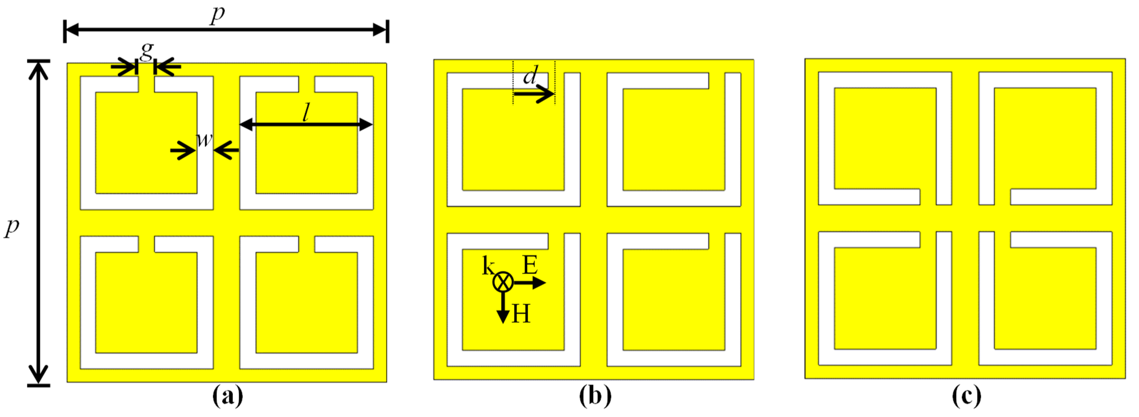
The three metasurface supercells studied in this paper are depicted in Figure 1. We start with a supercell shown in Figure 1a that consists of completely identical four complementary symmetric split-rectangular resonators (CS-SRRs) with the following dimensions: a side length of l = 50 μm, a width of w = 3 μm, and a gap of g = 3 μm of each CSRR, with a period of p = 120 μm of the supercell. The metallic sheet thickness of aluminum is 200 nm. The nonmirrored supercell is shown in Figure 1b, where the microstrip gap is moved by an asymmetry distance (d) of 20.5 μm for all four CS-SRRs. Next, the top two resonators in Figure 1b are mirrored vertically around their axis. Then, the two resonators on the right-hand side are mirrored horizontally around their axis. The final mirrored supercell depicted in Figure 1c represents a supercell composed of four complementary mirrored asymmetric split-rectangular resonators (CM-ASRs).
The numerical simulations have been carried out using the commercial software package Computer Simulation Technology (CST) Microwave Studio [38]. As the amplitude response of the proposed designs is expected to feature somewhat sharp resonances with high Q-factor, it was important to choose the frequency-domain solver of this package as it is recommended in such a situation. As the final device will be a two-dimensional array of the proposed supercells, unit-cell periodic boundary conditions have been used to mimic the actual scenario. The number of Floquet modes for both transmitting and receiving ports of the simulation setup was set to 20. Moreover, a tetrahedral mesh scheme with adaptive wavelength refinement was utilized and the number of result data samples was set to 5001. The yellow color in Figure 1 represents aluminum, and the white color is basically air. The electric field orientation has been chosen to be horizontally polarized with normal incidence excitation, as designated in the inset of Figure 1b. Thus, the inductive-capacitive (LC) resonance can only be excited when asymmetry distance (d) is greater than 0. The question is: What will happen when we mirror the resonators as in Figure 1c?
3. Mirrored vs. Nonmirrored Supercells Results and Discussion
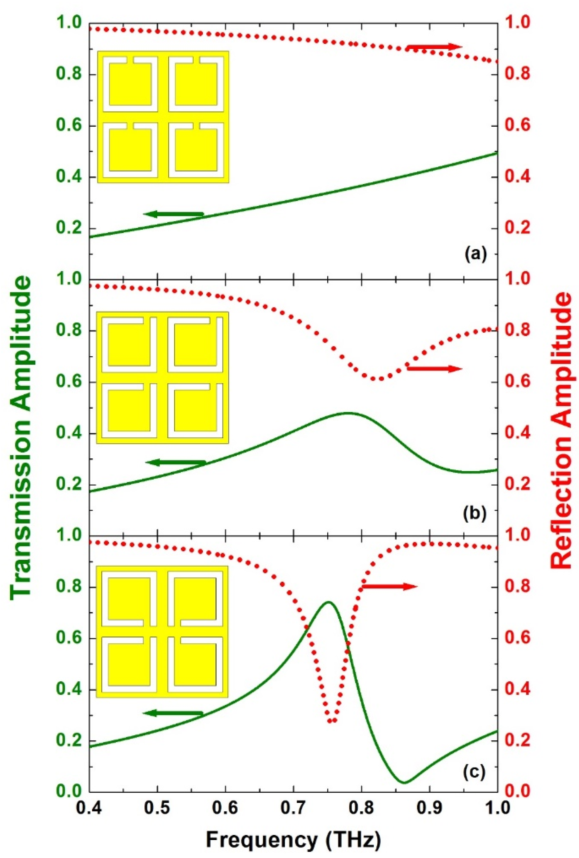
Figure 2 shows the simulated transmission (green, solid-curve in the left-scale) and reflection (red, dashed-curve in the right-scale) amplitude results for the three structures depicted in Figure 1. The supercell of each structure is depicted as an inset in each part of Figure 2 for clarity. Figure 1a presents the results of the symmetric structure. Due to the fact that the electric field is horizontally polarized, we expect the excitation of the dipole mode to only be shown at higher frequencies (not shown here). Indeed, no resonance feature is noticed in this configuration as expected. The results of the nonmirrored design are shown in Figure 1b, where the gap has been moved by 20.5 μm.
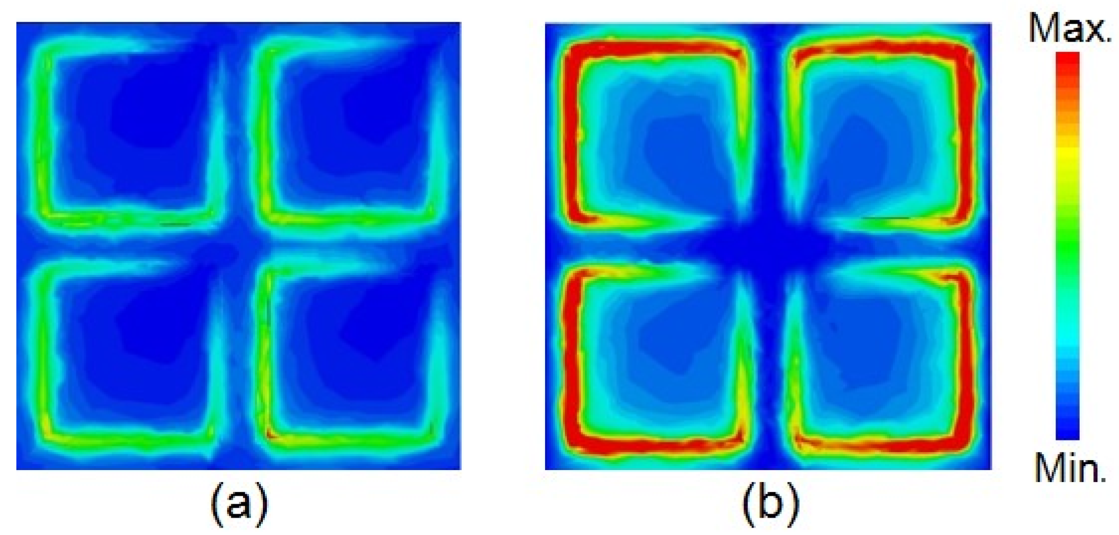
In this case, we notice the excitation of a weak LC resonance. The sharpness of the resonance can be assessed by evaluating its Q-factor. It is defined as the ratio between full-width half-maximum (FWHM) bandwidth and the resonance frequency (fr). As a result, we observe the excitation of a broad spectral response with FWHM of 231 GHz at the resonance frequency (fr) of 0.78 THz. Hence, the Q-factor (fr/FWHM) is 3.4. Remarkably, a much sharper spectral response is revealed when the mirrored design depicted as an inset in Figure 2c is used. It features FWHM of 90 GHz at a resonance frequency of 0.76 THz and hence a Q-factor of 8.44. Therefore, comparing the Q-factor of the mirrored supercell to the nonmirrored supercell, the improvement factor is two and a half times larger. This is a direct result of enhanced out-of-phase dipole moments that resulted from mirroring the resonators [31]. The resonance of the mirrored structure in part (c) of the figure is slightly red-shifted and can be interpreted to the increased coupling in the mirrored resonators. In order to get an insight into the electric field distribution of both nonmirrored supercell shown in Figure 1b and mirrored supercell shown in Figure 1c, the electric field spatial distribution at the surface of both metasurfaces at the resonance frequency is demonstrated in Figure 3. It is evident that once the resonators are mirrored as depicted in Figure 3b of the figure, a much larger electric field can be confined within the complementary resonators, i.e., in the area where there is no metal. This not only helps in understanding why the Q-factor has been improved but also visualizes the areas where the analyte can be placed. In this case, it is not needed or useful to cover the whole device, except in areas with high field confinement. It is worth mentioning that this issue was a topic of a recent paper [14]. So, if we coat two sides of the resonators where the E-field is highly confined, we will need to coat only {[(w = 3) × (l = 50) × (2 sides of each resonator) × (4 resonators)]/[total area = p2 = 120 × 120] = 1/12} of the whole area. This means only 8% of the whole device is required to be covered with the analyte. Therefore, the required analyte volume is reduced by 92%. It is also worth mentioning that the same results would be achieved if the gaps were moved to the opposite sides or placed on the outer corner of the structure. The final overall structure would feature the exact same frequency response.
4. Mirrored Supercell Sensor Evaluation
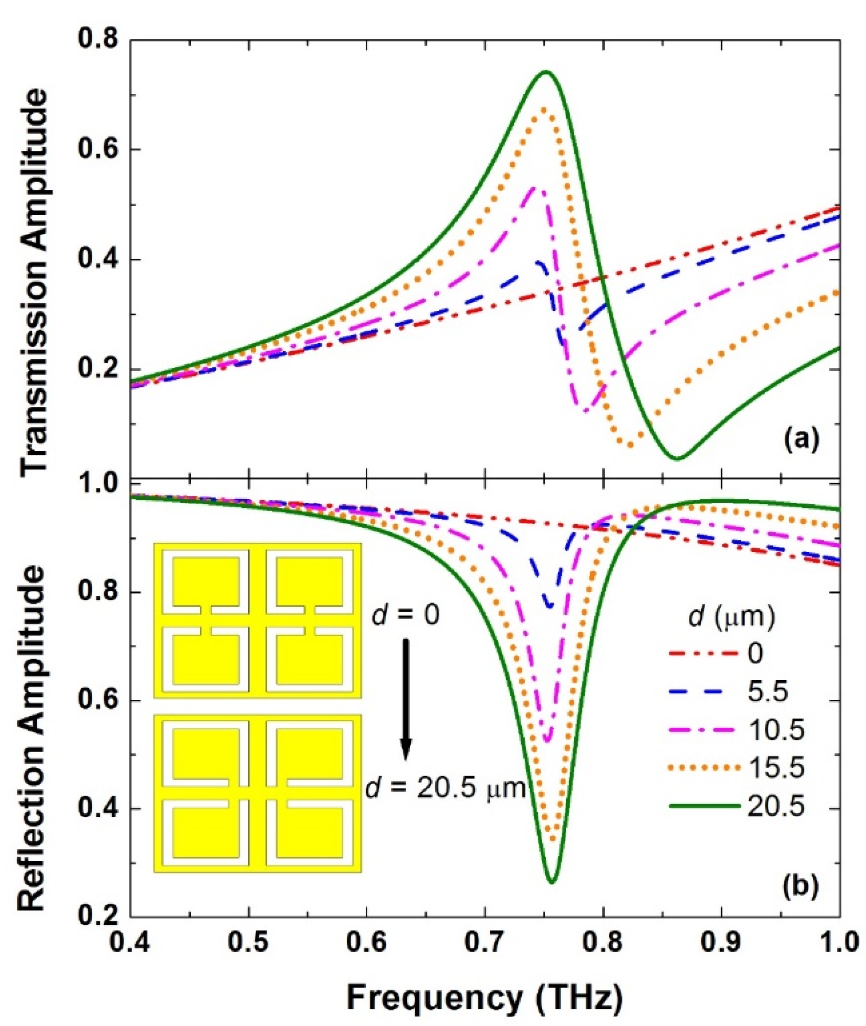
In order to evaluate the effect of the gap position, a parametric study of the mirrored structure was performed. This was done to reveal the influence of the asymmetry of the mirrored supercell design on the radiative properties. Figure 4 shows the transmission and reflection amplitude spectra for a sweep of values of d = 0, 5.5, 10.5, 15.5, and 20.5 μm. The resonance broadens, and hence the Q-factor decreases as the asymmetry distance increases while the modulation depth, defined here by the depth of the resonance of the reflection response, increases. By increasing the asymmetry distance from 5.5 μm to 20.5 μm, the Q-factor decreases from 20.4 to 8.4 and the modulation depth increases from 15.6% to 66.7%, respectively. These results reveal a clear trade-off between the modulation depth and the Q-factor of the resonance. In fact, a modulation depth of 15.6%, where we get a Q-factor of 20.4, can be easily measured using commercially available terahertz spectrometers [39].
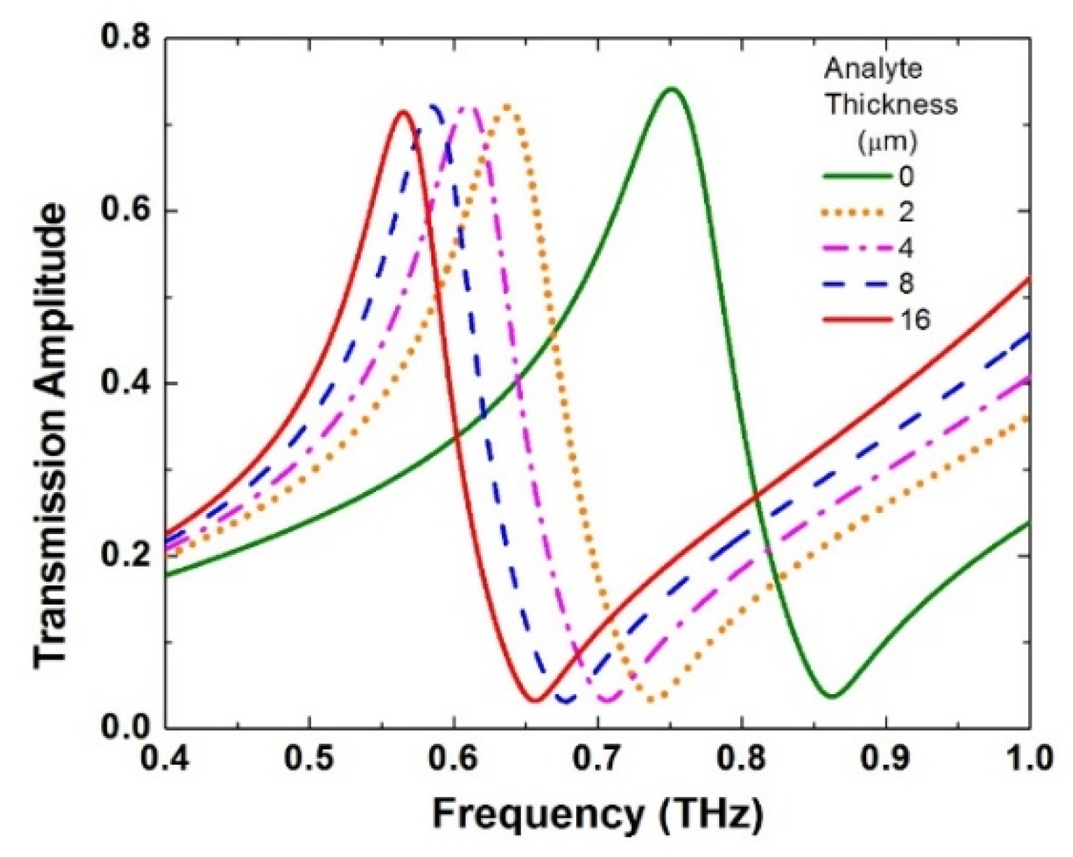
Next, we investigate the sensitivity of the mirrored design by sweeping the analyte thickness. As the range of biomolecules refractive index (n) ranges between 1.4 and 2.0 [40], we choose an average value of 1.6 to carry out this investigation. Multiple simulations have been performed by sweeping the analyte thickness between 2 μm and 16 μm. This procedure is essential in order to evaluate the performance of the sensors and their effectiveness. Figure 5 presents the transmission amplitude spectra, where the asymmetric resonance reveals a clear redshift of 114.5, 140.8, 166.6, and 186.5 GHz for analyte thickness of 2, 4, 8, and 16 μm, respectively. A significant redshift is achieved with quite a small change of only 2 μm thickness. Hence, changing the dielectric environment by even a minute amount by applying a 2 μm thickness of analyte onto the sensor results in a large redshift of [(resonance shift = 114.5 GHz)/(fr = 750 GHz) = 15.3%]. The shift is increased by a small amount only to reach 24.9% when the analyte thickness is increased to 16 μm. This is due to the limited interaction between the THz field and the metasurface sensor when the analyte thickness is larger than 8 μm. It is important to note that this kind of sensor is meant to sense thin-film analytes, i.e., a thickness of 4 μm or less.
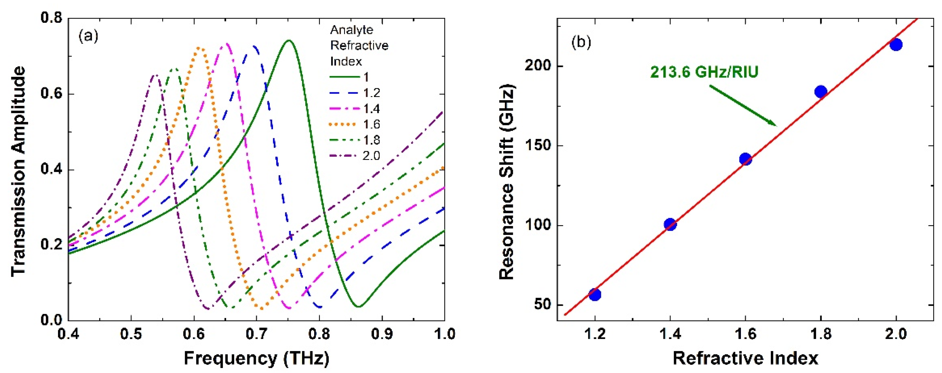
Finally, we studied the effect of different values of the refractive index of the analyte on the sensor performance. We carried out a series of simulations by sweeping the refractive index between 1.0 and 2.0, while the analyte thickness was fixed at 4 μm, as shown in Figure 6a. The resulting resonance shift (df) is shown to be 56.6, 100.6, 140.8, 184, and 213.6 GHz for the refractive index of 1.2, 1.4, 1.6, 1.8, and 2.0, respectively. Figure 6b shows the resonance shifts and the linear fitting, which gives a slope of 213.6 GHz per refractive index unit (RIU). This slope is sometimes considered a measure of the sensor sensitivity. However, the well-known measure is the wavelength sensitivity using [14,17]:
where “co” is the speed of light in free space. The latter is a more comprehensive approach, as the resonance frequency is considered in the calculations. For the proposed mirrored design in this paper, very high sensitivity of 1.14 × 10⁵ nm/RIU has been achieved. As actual biomolecules contain water, the effect of the imaginary part of the refractive index has been investigated in this regard [29]. As expected, no resonance shift was observed at all. However, there was a reduction in the amplitude depth of the resonance. This suggests that resonances with a large amplitude modulation are preferred in order to get reasonable measurements at the detector side.
5. Conclusions
In conclusion, we have demonstrated complementary THz metasurfaces consists of a free-standing supercell composed of four complementary mirrored asymmetric split-rectangular resonators. A careful evaluation of the performance of the mirrored design has been carried out. Clear evidence of high field confinement is observed in the supercell of the four CM-ASRs. Moreover, we demonstrated that the mirrored design outperforms its counterpart nonmirrored supercell by at least 250%. More importantly, we investigated the performance of this design for biosensing applications. A high sensitivity level of 1.14 × 10⁵ nm/RIU has been attained. Such devices represent potential candidates for future biomedical sensors to identify very small amounts of analytes.
Funding
This research received no external funding.
Conflicts of Interest
The author declares no conflict of interest.
References
- Averitt, R.D. Metamaterials: A stamp of quality. Nat. Nanotechnol. 2011, 6, 396–397. [Google Scholar] [CrossRef] [PubMed]
- Wu, C.; Khanikaev, A.B.; Adato, R.; Arju, N.; Yanik, A.A.; Altug, H.; Shvets, G. Fano-resonant asymmetric metamaterials for ultrasensitive spectroscopy and identification of molecular monolayers. Nat. Mater. 2011, 11, 69–75. [Google Scholar] [CrossRef]
- Pendry, J. Optics: All smoke and metamaterials. Nature 2009, 460, 579–580. [Google Scholar] [CrossRef]
- Choi, M.; Lee, S.H.; Kim, Y.; Kang, S.B.; Shin, J.; Kwak, M.H.; Kang, K.Y.; Lee, Y.H.; Park, N.; Min, B. A terahertz metamaterial with unnaturally high refractive index. Nature 2011, 470, 369–373. [Google Scholar] [CrossRef] [PubMed]
- Soukoulis, C.M.; Linden, S.; Wegener, M. Negative refractive index at optical wavelengths. Science 2007, 315, 47–50. [Google Scholar] [CrossRef]
- Pendry, J.B. A chiral route to negative refraction. Science 2004, 306, 1353–1355. [Google Scholar] [CrossRef] [Green Version]
- Chen, H.-T.; Taylor, A.J.; Yu, N. A review of metasurfaces: Physics and applications. Rep. Prog. Phys. 2016, 79, 76401. [Google Scholar] [CrossRef] [Green Version]
- Hara, J.F.O.; Singh, R.; Brener, I.; Smirnova, E.; Han, J.; Taylor, A.J.; Zhang, W. Thin-film sensing with planar terahertz metamaterials: Sensitivity and limitations. Opt. Express 2008, 16, 1786–1795. [Google Scholar] [CrossRef]
- Tao, H.; Padilla, W.J.; Zhang, X.; Averitt, R.D. Recent progress in electromagnetic metamaterial devices for Terahertz applications. IEEE J. Sel. Top. Quantum Electron. 2011, 17, 92–101. [Google Scholar] [CrossRef]
- Al-Naib, I.; Withayachumnankul, W. Recent Progress in Terahertz Metasurfaces. J. Infrared Millim. Terahertz Waves 2017, 38, 1067–1084. [Google Scholar] [CrossRef]
- O’Hara, J.F.; Withayachumnankul, W.; Al-Naib, I. A Review on Thin-film Sensing with Terahertz Waves. J. Infrared Millim. Terahertz Waves 2012, 33, 245–291. [Google Scholar] [CrossRef]
- Al-Naib, I.; Singh, R.; Shalaby, M.; Ozaki, T.; Morandotti, R. Enhanced Q-factor in Optimally Coupled Macrocell THz Metamaterials: Effect of Spatial Arrangement. IEEE J. Sel. Top. Quantum Electron. 2013, 19, 8400807. [Google Scholar] [CrossRef]
- Brucherseifer, M.; Nagel, M.; Haring Bolivar, P.; Kurz, H.; Bosserhoff, A.; Buettner, R. Label-free probing of the binding state of DNA by time-domain terahertz sensing. Appl. Phys. Lett. 2000, 77, 4049–4051. [Google Scholar] [CrossRef] [Green Version]
- Al-Naib, I. Biomedical sensing with conductively coupled terahertz metamaterial resonators. IEEE J. Sel. Top. Quantum Electron. 2017, 23, 4700405. [Google Scholar] [CrossRef]
- Al-Naib, I. Thin-Film Sensing via Fano Resonance Excitation in Symmetric Terahertz Metamaterials. J. Infrared Millim. Terahertz Waves 2018, 39, 1–5. [Google Scholar] [CrossRef]
- Cong, L.; Tan, S.; Yahiaoui, R.; Yan, F.; Zhang, W.; Singh, R. Experimental demonstration of ultrasensitive sensing with terahertz metamaterial absorbers: A comparison with the metasurfaces. Appl. Phys. Lett. 2015, 106, 31107. [Google Scholar] [CrossRef]
- Singh, R.; Cao, W.; Al-Naib, I.; Cong, L.; Withayachumnankul, W.; Zhang, W. Ultrasensitive terahertz sensing with high-Q Fano resonances in metasurfaces. Appl. Phys. Lett. 2014, 105, 171101. [Google Scholar] [CrossRef] [Green Version]
- Gupta, M.; Srivastava, Y.K.; Manjappa, M.; Singh, R. Sensing with Toroidal Metamaterial. Appl. Phys. Lett. 2017, 110, 121108. [Google Scholar] [CrossRef]
- Tao, H.; Chieffo, L.R.; Brenckle, M.A.; Siebert, S.M.; Liu, M.; Strikwerda, A.C.; Fan, K.; Kaplan, D.L.; Zhang, X.; Averitt, R.D.; et al. Metamaterials on paper as a sensing platform. Adv. Mater. 2011, 23, 3197–3201. [Google Scholar] [CrossRef]
- Jansen, C.; Al-Naib, I.A.I.; Born, N.; Koch, M. Terahertz metasurfaces with high Q-factors. Appl. Phys. Lett. 2011, 98, 51109. [Google Scholar] [CrossRef]
- Li, T.Q.; Liu, H.; Li, T.; Wang, S.M.; Cao, J.X.; Zhu, Z.H.; Dong, Z.G.; Zhu, S.N.; Zhang, X. Suppression of radiation loss by hybridization effect in two coupled split-ring resonators. Phys. Rev. B 2009, 80, 115113. [Google Scholar] [CrossRef] [Green Version]
- Fedotov, V.A.; Rose, M.; Prosvirnin, S.L.; Papasimakis, N.; Zheludev, N.I. Sharp trapped-mode resonances in planar metamaterials with a broken structural symmetry. Phys. Rev. Lett. 2007, 99, 147401. [Google Scholar] [CrossRef] [Green Version]
- Singh, R.; Al-Naib, I.A.I.; Koch, M.; Zhang, W. Sharp Fano resonances in THz metamaterials. Opt. Express 2011, 19, 6312–6319. [Google Scholar] [CrossRef] [PubMed] [Green Version]
- Luk’Yanchuk, B.; Zheludev, N.I.; Maier, S.A.; Halas, N.J.; Nordlander, P.; Giessen, H.; Chong, C.T. The Fano resonance in plasmonic nanostructures and metamaterials. Nat. Mater. 2010, 9, 707–715. [Google Scholar] [CrossRef] [PubMed]
- Al-Naib, I.A.I.; Jansen, C.; Koch, M. Thin-film sensing with planar asymmetric metamaterial resonators. Appl. Phys. Lett. 2008, 93, 083507. [Google Scholar] [CrossRef]
- Singh, R.; Al-Naib, I.A.I.; Koch, M.; Zhang, W. Asymmetric planar terahertz metamaterials. Opt. Express 2010, 18, 13044–13050. [Google Scholar] [CrossRef] [Green Version]
- Singh, R.; Al-Naib, I.; Cao, W.; Rockstuhl, C.; Koch, M.; Zhang, W. The Fano Resonance in Symmetry Broken Terahertz Metamaterials. IEEE Trans. Terahertz Sci. Technol. 2013, 3, 820–826. [Google Scholar] [CrossRef]
- Shih, K.; Pitchappa, P.; Manjappa, M.; Ho, C.P.; Singh, R.; Lee, C. Microfluidic metamaterial sensor—Selective trapping and remote sensing of microparticles. J. Appl. Phys. 2017, 121, 023102. [Google Scholar] [CrossRef]
- Shih, K.; Pitchappa, P.; Jin, L.; Chen, C.; Singh, R.; Lee, C. Nanofluidic terahertz metasensor for sensing in aqueous environment. Appl. Phys. Lett. 2018, 113, 071105. [Google Scholar] [CrossRef] [Green Version]
- Sreekanth, K.V.; Sreejith, S.; Alapan, Y.; Sitti, M.; Lim, C.T.; Singh, R. Microfluidics Integrated Lithography-Free Nanophotonic Biosensor for the Detection of Small Molecules. Adv. Opt. Mater. 2019, 7, 1–6. [Google Scholar] [CrossRef]
- Al-Naib, I.; Singh, R.; Rockstuhl, C.; Lederer, F.; Delprat, S.; Rocheleau, D.; Chaker, M.; Ozaki, T.; Morandotti, R. Excitation of a high-Q subradiant resonance mode in mirrored single-gap asymmetric split ring resonator terahertz metamaterials. Appl. Phys. Lett. 2012, 101, 071108. [Google Scholar] [CrossRef]
- Al-Naib, I.; Hebestreit, E.; Rockstuhl, C.; Lederer, F.; Christodoulides, D.; Ozaki, T.; Morandotti, R. Conductive coupling of split ring resonators: A path to THz metamaterials with ultrasharp resonances. Phys. Rev. Lett. 2014, 112, 183903. [Google Scholar] [CrossRef] [PubMed] [Green Version]
- Al-Naib, I.; Yang, Y.; Dignam, M.M.; Zhang, W.; Singh, R. Ultra-high Q even eigenmode resonance in terahertz metamaterials. Appl. Phys. Lett. 2015, 106, 11102. [Google Scholar] [CrossRef]
- Al-Naib, I. Novel terahertz metasurfaces based on complementary coupled split ring resonators. Opt. Mater. 2020, 99, 109596. [Google Scholar] [CrossRef]
- Al-Naib, I.A.I.; Jansen, C.; Koch, M. Applying the Babinet principle to asymmetric resonators. Electron. Lett. 2008, 44, 1228–1229. [Google Scholar] [CrossRef]
- Born, N.; Gente, R.; Al-Naib, I.; Koch, M. Laser beam machined free-standing terahertz metamaterials. Electron. Lett. 2015, 51, 1012–1014. [Google Scholar] [CrossRef]
- Taleb, F.; Al-Naib, I.; Koch, M. Free-Standing Complementary Asymmetric Metasurface for Terahertz Sensing Applications. Sensors 2020, 20, 1–8. [Google Scholar] [CrossRef]
- CST Studio Suite 3D EM Simulation and Analysis Software. Available online: https://www.3ds.com/products-services/simulia/products/electromagnetic-simulation/ (accessed on 5 May 2020).
- Vieweg, N.; Rettich, F.; Deninger, A.; Roehle, H.; Dietz, R.; Göbel, T.; Schell, M. Terahertz-time domain spectrometer with 90 dB peak dynamic range. J. Infrared Millim. Terahertz Waves 2014, 35, 823–832. [Google Scholar] [CrossRef]
- Yahiaoui, R.; Strikwerda, A.C.; Jepsen, P.U. Terahertz plasmonic structure with enhanced sensing capabilities. IEEE Sens. J. 2016, 16, 2484–2488. [Google Scholar] [CrossRef] [Green Version]
Figure 1.
Schematic of the three supercells: (a) symmetric supercell consists of four complementary symmetric split-rectangular resonators, (b) asymmetric supercell consists of four complementary nonmirrored asymmetric split-rectangular resonators explaining the asymmetric distance (d), and (c) asymmetric mirrored supercell consists of four complementary mirrored asymmetric split-rectangular resonators. The inset in part (b) shows the field polarization. The real value of g and w’s distances have been doubled for clarity.

Figure 2.
Transmission (left-axis) and reflection (right axis) spectra of the (a) complementary symmetric split-rectangular resonators supercell, (b) complementary nonmirrored asymmetric split-rectangular resonators supercell, and (c) complementary mirrored asymmetric split-rectangular resonators supercell. The insets in parts (a–c) are the same structures as in Figure 1.

Figure 3.
Electric field spatial distribution at the surface of the device at the resonance frequency for (a) a complementary nonmirrored asymmetric split-rectangular resonators supercell and (b) a complementary mirrored asymmetric split-rectangular resonators supercell.
Figure 3.
Electric field spatial distribution at the surface of the device at the resonance frequency for (a) a complementary nonmirrored asymmetric split-rectangular resonators supercell and (b) a complementary mirrored asymmetric split-rectangular resonators supercell.

Figure 4.
(a) Transmission and (b) reflection amplitude spectra of complementary mirrored asymmetric split-rectangular resonators supercell for a sweep of asymmetric distance (d) of 0, 5.5, 10.5, 15.5, and 20.5 μm.
Figure 4.
(a) Transmission and (b) reflection amplitude spectra of complementary mirrored asymmetric split-rectangular resonators supercell for a sweep of asymmetric distance (d) of 0, 5.5, 10.5, 15.5, and 20.5 μm.

Figure 5.
Transmission amplitude spectra of the complementary mirrored asymmetric split-rectangular resonators when not covered with any analyte (green solid curve) and when covered by analyte (n = 1.6) of thicknesses of 2, 4, 8, and 16 μm.
Figure 5.
Transmission amplitude spectra of the complementary mirrored asymmetric split-rectangular resonators when not covered with any analyte (green solid curve) and when covered by analyte (n = 1.6) of thicknesses of 2, 4, 8, and 16 μm.

Figure 6.
(a) Transmission amplitude spectra of the complementary mirrored asymmetric split-rectangular resonators when not covered with any analyte (green, solid-curve) and when covered by analyte with a thickness of 4 μm for a range of refractive index values. (b) Resonance shift versus the refractive index of the analyte when the thickness of the analyte is kept at 4 μm.

© 2020 by the author. Licensee MDPI, Basel, Switzerland. This article is an open access article distributed under the terms and conditions of the Creative Commons Attribution (CC BY) license (http://creativecommons.org/licenses/by/4.0/).
Share and Cite
MDPI and ACS Style
Al-Naib, I. Biomedical Sensing with Free-Standing Complementary Supercell Terahertz Metasurfaces. Crystals 2020, 10, 372. https://doi.org/10.3390/cryst10050372
AMA Style
Al-Naib I. Biomedical Sensing with Free-Standing Complementary Supercell Terahertz Metasurfaces. Crystals. 2020; 10(5):372. https://doi.org/10.3390/cryst10050372
Chicago/Turabian StyleAl-Naib, Ibraheem. 2020. "Biomedical Sensing with Free-Standing Complementary Supercell Terahertz Metasurfaces" Crystals 10, no. 5: 372. https://doi.org/10.3390/cryst10050372
Note that from the first issue of 2016, this journal uses article numbers instead of page numbers. See further details here.