


1 Introduction
Nanosecond fiber lasers have attracted much research interest in recent years due to advantages of relatively low cost and flexible operation window compared with their
 $Q$
-switched solid-state counterparts. Besides, increasing application demand in wide fields has also promoted the development of the ns fiber laser, such as laser processing[Reference Veiko, Karlagina, Moskvin, Mikhailovskii, Odintsova, Olshin, Pankin, Romanov and Yatsuk1, Reference Williams, Brousseau and Rees2], nonlinear frequency conversion[Reference Qiao, Zhao, Yang, Zhao, Li, Li, Li, Qiao and Wang3, Reference Fang, Cui, Zhang, Qi, Shi, Li and Zhou4], coherent beam combining[Reference Su, Zhou, Wang, Zhang and Xu5–Reference Tsubakimoto, Yoshida and Miyanaga7], laser lidar[Reference Philippov, Codemard, Jeong, Alegria, Sahu, Nilsson and Pearson8, Reference Liu, Liu and Chen9], generation of vector beam[Reference Huang, Yi, Jiang, Miao, Hu, Zhao and Wen10], and terahertz generation[Reference Shi, Leigh, Zong, Yao, Nguyen, Arturo and Nasser11]. Generally, the most common method to obtain ns fiber laser is the
$Q$
-switched solid-state counterparts. Besides, increasing application demand in wide fields has also promoted the development of the ns fiber laser, such as laser processing[Reference Veiko, Karlagina, Moskvin, Mikhailovskii, Odintsova, Olshin, Pankin, Romanov and Yatsuk1, Reference Williams, Brousseau and Rees2], nonlinear frequency conversion[Reference Qiao, Zhao, Yang, Zhao, Li, Li, Li, Qiao and Wang3, Reference Fang, Cui, Zhang, Qi, Shi, Li and Zhou4], coherent beam combining[Reference Su, Zhou, Wang, Zhang and Xu5–Reference Tsubakimoto, Yoshida and Miyanaga7], laser lidar[Reference Philippov, Codemard, Jeong, Alegria, Sahu, Nilsson and Pearson8, Reference Liu, Liu and Chen9], generation of vector beam[Reference Huang, Yi, Jiang, Miao, Hu, Zhao and Wen10], and terahertz generation[Reference Shi, Leigh, Zong, Yao, Nguyen, Arturo and Nasser11]. Generally, the most common method to obtain ns fiber laser is the
 $Q$
-switched regime that is based on various saturation absorbers[Reference Morshed, Hattori, Haque and Olbricht12, Reference Wang, Li, Xing, Chen, Wei and Wang13], nonlinear effect[Reference Xu, Luo, Yang, Peng, Li and Li14], acoustic–optical modulator (AOM)[Reference Stutzki, Jansen, Liem, Jauregui, Limpert and Tunnermann15], stress-induced birefringence[Reference Shi, Petersen, Yao, Nguyen, Zong, Stephen, Chavez-Pirson and Peyghambarian16], tilted fiber grating [Reference Wang, Yan, Mou, Zhou and Zhang17] and direct pump modulation[Reference Malinowski, Gorman, Codemard, Ghiringhelli, Boyland, Marshall, Zervas and Durkin18, Reference Hou, Zhang, Qi, Feng and Wang19], and so on. Another important approach is the external modulation of a continuous wave (CW) laser[Reference Leigh, Shi, Zong and Yao20–Reference Wang, Jin, Zhou, Wang, Xiao and Liu23]. However, the output power of the methods directly based on either
$Q$
-switched regime that is based on various saturation absorbers[Reference Morshed, Hattori, Haque and Olbricht12, Reference Wang, Li, Xing, Chen, Wei and Wang13], nonlinear effect[Reference Xu, Luo, Yang, Peng, Li and Li14], acoustic–optical modulator (AOM)[Reference Stutzki, Jansen, Liem, Jauregui, Limpert and Tunnermann15], stress-induced birefringence[Reference Shi, Petersen, Yao, Nguyen, Zong, Stephen, Chavez-Pirson and Peyghambarian16], tilted fiber grating [Reference Wang, Yan, Mou, Zhou and Zhang17] and direct pump modulation[Reference Malinowski, Gorman, Codemard, Ghiringhelli, Boyland, Marshall, Zervas and Durkin18, Reference Hou, Zhang, Qi, Feng and Wang19], and so on. Another important approach is the external modulation of a continuous wave (CW) laser[Reference Leigh, Shi, Zong and Yao20–Reference Wang, Jin, Zhou, Wang, Xiao and Liu23]. However, the output power of the methods directly based on either
 $Q$
-switching or external modulation is generally too low to satisfy the application demand. So, the master oscillator power amplifier (MOPA) configuration is usually employed for high power scaling[Reference Ran, Su, Ma, Wang, Lü, Zhou and Si22, Reference Dvoyrin, Klimentov, Klepsvik, Mazaeva and Sorokina24–Reference Su, Zhou, Wang, Tao and Xu26]. In 2014, Su et al. realized a kW-level ns fiber MOPA, which is the highest output power of the all-fiberized ns fiber laser with a random polarization up to now [Reference Su, Zhou, Wang, Tao and Xu26]. However, the further power scaling in that work was limited by the stimulated Raman scattering (SRS) and the linewidth was broadened to a relatively wide one. Furthermore, the linear polarization is more preferred in some special applications, e.g., nonlinear frequency conversion[Reference Liu, Norsen and Mead27] and coherent polarization beam combing[Reference Liu, Ma, Su, Tao, Ma, Wang and Zhou28]. In 2015, Avdokhin et al. achieved an all-fiberized ns MOPA of 1.03 kW with linear polarization and generated 700 W green laser by efficient frequency doubling, with further power scaling inhibited by SRS and the mode instability (MI)[Reference Avdokhin, Gapontsev, Kadwani, Vaupel, Samartsev, Platonov, Yusim and Myasnikov29]. In that work, the seed linewidth was broadened to be a relatively wide level of more than 20 GHz to suppress another detrimental nonlinear effect – stimulated Brillouin scattering (SBS), which may be not preferred in the applications where narrower linewidth is needed.
$Q$
-switching or external modulation is generally too low to satisfy the application demand. So, the master oscillator power amplifier (MOPA) configuration is usually employed for high power scaling[Reference Ran, Su, Ma, Wang, Lü, Zhou and Si22, Reference Dvoyrin, Klimentov, Klepsvik, Mazaeva and Sorokina24–Reference Su, Zhou, Wang, Tao and Xu26]. In 2014, Su et al. realized a kW-level ns fiber MOPA, which is the highest output power of the all-fiberized ns fiber laser with a random polarization up to now [Reference Su, Zhou, Wang, Tao and Xu26]. However, the further power scaling in that work was limited by the stimulated Raman scattering (SRS) and the linewidth was broadened to a relatively wide one. Furthermore, the linear polarization is more preferred in some special applications, e.g., nonlinear frequency conversion[Reference Liu, Norsen and Mead27] and coherent polarization beam combing[Reference Liu, Ma, Su, Tao, Ma, Wang and Zhou28]. In 2015, Avdokhin et al. achieved an all-fiberized ns MOPA of 1.03 kW with linear polarization and generated 700 W green laser by efficient frequency doubling, with further power scaling inhibited by SRS and the mode instability (MI)[Reference Avdokhin, Gapontsev, Kadwani, Vaupel, Samartsev, Platonov, Yusim and Myasnikov29]. In that work, the seed linewidth was broadened to be a relatively wide level of more than 20 GHz to suppress another detrimental nonlinear effect – stimulated Brillouin scattering (SBS), which may be not preferred in the applications where narrower linewidth is needed.

Figure 1. The experimental setup of the ns pulsed seed.
To overcome the nonlinear effects preventing power scaling, especially the SBS which is primary limitation factor of high power ns fiber laser, the photonic crystal fiber (PCF) with ultra-large mode area has been used for yielding high energy or high peak power but was characterized with the bulk optics which might complicate the system[Reference Stutzki, Jansen, Liem, Jauregui, Limpert and Tunnermann15, Reference Brooks and Teodoro30]. The intensity modulation of the CW laser seed combined with the synchronous phase modulation is also effective to suppress the SBS[Reference Ran, Su, Ma, Wang, Lü, Zhou and Si22], but the output linewidth is relatively wide due to the phase modulation. Due to large mode area and relatively short required fiber length that benefits the suppression of the nonlinear effects and the spectral broadening, the conventional large-mode-area (LMA) double cladding fiber with high doping concentration is a promising candidate for forming all-fiber structures to obtain high output power in a wide duration range from the nanosecond to the femtosecond[Reference Yu, Tao, Wang, Zhou and Chen31–Reference Yu, Wang, Zhang, Su, Zhou and Chen33], especially for the narrow linewidth output.
In this paper, we demonstrate an all-fiberized high-average-power narrow linewidth ns pulsed laser with linear polarization, based on MOPA configuration comprising an externally modulated ns seed and four-stage amplifiers. By adopting a polarization maintained (PM) LMA fiber with high doping concentration and short length, combined with narrow pulse duration, the SBS and SRS are suppressed effectively at the maximal output power of 466 W with a narrow linewidth of 203.6 MHz. The pulse duration and repetition rate are 4 ns and 10 MHz, respectively, corresponding to a peak power of 8.8 kW and pulse energy of
 $46.6~\unicode[STIX]{x03BC}\text{J}$
. The polarization degree and the slope efficiency are 90% and 80.3%, respectively. Near-diffraction-limited beam quality with an
$46.6~\unicode[STIX]{x03BC}\text{J}$
. The polarization degree and the slope efficiency are 90% and 80.3%, respectively. Near-diffraction-limited beam quality with an
 $M^{2}$
factor of 1.32 is obtained at the output power of 442 W and the MI is observed at the maximal output power. To the best of our knowledge, this is the highest average output power of the all-fiberized narrow linewidth ns pulsed fiber laser with linear polarization and high beam quality, which is a promising source for the nonlinear frequency conversion, laser lidar and so on.
$M^{2}$
factor of 1.32 is obtained at the output power of 442 W and the MI is observed at the maximal output power. To the best of our knowledge, this is the highest average output power of the all-fiberized narrow linewidth ns pulsed fiber laser with linear polarization and high beam quality, which is a promising source for the nonlinear frequency conversion, laser lidar and so on.
2 Experimental setup
2.1 The ns pulsed seed
The experimental setup has a typical MOPA configuration comprising a ns pulsed seed (Figure 1) and four-stage amplifiers. All fiber-based components in the system utilize the PM fiber. In the ns pulsed seed, a CW linearly polarized single frequency laser based on the ultra-short cavity[Reference Xu, Yang, Zhang, Wei, Qian, Chen, Zhang, Shen, Peng and Qiu34] is modulated by an electrical–optical intensity modulator (EOIM) to generate the ns pulses. The CW single frequency laser emits an output power of 42 mW at the center wavelength of 1064 nm, with a nominal linewidth of 20 kHz. The EOIM has a response bandwidth beyond 10 GHz and a handling power range within 100 mW, driven by an arbitrary function generator (AFG). The pulse width and the repetition frequency of the drive signal are set to 4 ns and 10 MHz, respectively. After the EOIM, the generated pulses with an average power of 0.48 mW are injected into a low power amplifier. The low power amplifier utilizes a 1-m-long single-mode double cladding PM Yb-doped fiber (YDF) with core/inner cladding diameters of
 $6/125~\unicode[STIX]{x03BC}\text{m}$
, pumped by a laser diode (LD) emitting the wavelength of 974 nm through a wavelength division multiplexer (WDM). After a PM bandpass filter (BPF) and a PM isolator (ISO), the amplified ns pulses are launched into an AOM to remove the leakage among the pulses and improve the pulse extinction ratio. The AOM has a rise/fall time of 30 ns and a handling power capacity of 5 W. After the AOM, a coupler with a coupling ratio of 5:95 is used to split the laser beam into two parts. The part from the 5% port is used to monitor the properties of the ns pulses in real time. The part from the 95% port is finally injected into the following amplifiers as the seed, with an average output power of 2 mW.
$6/125~\unicode[STIX]{x03BC}\text{m}$
, pumped by a laser diode (LD) emitting the wavelength of 974 nm through a wavelength division multiplexer (WDM). After a PM bandpass filter (BPF) and a PM isolator (ISO), the amplified ns pulses are launched into an AOM to remove the leakage among the pulses and improve the pulse extinction ratio. The AOM has a rise/fall time of 30 ns and a handling power capacity of 5 W. After the AOM, a coupler with a coupling ratio of 5:95 is used to split the laser beam into two parts. The part from the 5% port is used to monitor the properties of the ns pulses in real time. The part from the 95% port is finally injected into the following amplifiers as the seed, with an average output power of 2 mW.
The pulse sequence of the ns pulsed seed is shown in Figure 2(a), captured by a digital oscilloscope at its highest sampling rate of 5 GS/s. The profile of the pulse sequence reveals good stability and high extinction ratio of the ns pulsed seed. The full width at half maximum (FWHM) of the ns pulsed seed is read to be
 ${\sim}$
4.4 ns, a little wider than the pulse width of the electrical drive signal imposed on the EOIM.
${\sim}$
4.4 ns, a little wider than the pulse width of the electrical drive signal imposed on the EOIM.

Figure 2. (a) The pulse sequence of the ns pulsed seed and (b) the pulse profile of the ns pulsed seed.
The spectral linewidth of the ns pulses is collaboratively measured by a Fabry–Pérot interferometer and a digital oscilloscope. The free spectral range and resolution of the Fabry–Pérot interferometer are 4 GHz and 10 MHz, respectively. As shown in Figure 3, the spectral linewidth is measured to be
 ${\sim}$
36.2 MHz, due to the spectral broadening induced by the intensity modulation.
${\sim}$
36.2 MHz, due to the spectral broadening induced by the intensity modulation.
2.2 The power amplifier stages
As shown in Figure 4, following the ns pulsed seed, there are three pre-amplifiers and a main amplifier. The 1st pre-amplifier and 2nd pre-amplifier employ the same components as the low power amplifier used in the pulsed seed, with the only difference that the 1st pre-amplifier is counter-pumped through the WDM but the 2nd pre-amplifier is co-pumped. After the 1st pre-amplifier and 2nd pre-amplifier, the average power of the ns pulses is boosted to be 23.6 mW and 184.9 mW, respectively. The 3rd pre-amplifier adopts a 2.5 m-long PM double cladding Yb-doped fiber with core/inner cladding diameters of
 $15/130~\unicode[STIX]{x03BC}\text{m}$
, pumped by a 25 W LD with 976 nm emitting wavelength. The absorption coefficient of the active fiber is
$15/130~\unicode[STIX]{x03BC}\text{m}$
, pumped by a 25 W LD with 976 nm emitting wavelength. The absorption coefficient of the active fiber is
 ${\sim}$
5.5 dB at 976 nm pump wavelength, and the core/cladding NAs are 0.078 and 0.46, respectively. The average power of the ns pulses is amplified to be
${\sim}$
5.5 dB at 976 nm pump wavelength, and the core/cladding NAs are 0.078 and 0.46, respectively. The average power of the ns pulses is amplified to be
 ${\sim}$
10 W, and then injected into the main amplifier after a PM ISO and a PM tapper with a beam splitting ratio of
${\sim}$
10 W, and then injected into the main amplifier after a PM ISO and a PM tapper with a beam splitting ratio of
 $0.1\%:99.9\%$
. Through the backward 0.1% port of the tapper, the backward power of the main amplifier is monitored to judge whether the SBS occurs or not.
$0.1\%:99.9\%$
. Through the backward 0.1% port of the tapper, the backward power of the main amplifier is monitored to judge whether the SBS occurs or not.

Figure 3. The scanning spectrum of the ns pulsed seed.

Figure 4. The experimental setup of the power amplifier stages.
In the main amplifier, a 3 m-long high concentration PM LMA double cladding Yb-doped fiber with core/inner cladding diameters of
 $30/250~\unicode[STIX]{x03BC}\text{m}$
is employed, pumped by six 976 nm LDs of
$30/250~\unicode[STIX]{x03BC}\text{m}$
is employed, pumped by six 976 nm LDs of
 ${\sim}$
100 W power via a (
${\sim}$
100 W power via a (
 $6+1$
)
$6+1$
)
 $\times$
1 signal/pump combiner. The core/inner cladding NAs are 0.073 and
$\times$
1 signal/pump combiner. The core/inner cladding NAs are 0.073 and
 ${>}$
0.46, respectively, and the absorption coefficient is as high as
${>}$
0.46, respectively, and the absorption coefficient is as high as
 ${\sim}$
13.6 dB at the 976 nm wavelength due to high doping concentration. After the active fiber, a 1.15 m-long passive fiber matched with the active fiber in size is followed to deliver the laser power, so the total fiber length of the main amplifier is
${\sim}$
13.6 dB at the 976 nm wavelength due to high doping concentration. After the active fiber, a 1.15 m-long passive fiber matched with the active fiber in size is followed to deliver the laser power, so the total fiber length of the main amplifier is
 ${\sim}$
4.15 m. Meantime, a pump stripper made from the high-index gel is arranged on the passive fiber to remove the cladding light, including the residual pump light and the cladding signal light. The output port of the passive fiber is cleaved with an oblique angle of
${\sim}$
4.15 m. Meantime, a pump stripper made from the high-index gel is arranged on the passive fiber to remove the cladding light, including the residual pump light and the cladding signal light. The output port of the passive fiber is cleaved with an oblique angle of
 $8^{\circ }$
, in order to prevent the end feedback and end damage.
$8^{\circ }$
, in order to prevent the end feedback and end damage.
3 Results and discussion
The dependence of the average output power and backward power on the pump power is shown in Figure 5. It is noted that the average output power scales linearly with the pump power increased, with a fitted slope efficiency of
 ${\sim}$
80.3%. When the pump power is 575 W, a maximal output power of 466 W is obtained without power roll-over observed. The corresponding pulse energy is calculated to be
${\sim}$
80.3%. When the pump power is 575 W, a maximal output power of 466 W is obtained without power roll-over observed. The corresponding pulse energy is calculated to be
 ${\sim}46.6~\unicode[STIX]{x03BC}\text{J}$
at the repetition frequency of 10 MHz. The backward power also increases with an approximately linear trend, indicating the absence of the SBS in the main amplifier. The absence of the SBS mainly benefits from the large mode area and the short fiber length of the main amplifier and the narrow pulse duration of
${\sim}46.6~\unicode[STIX]{x03BC}\text{J}$
at the repetition frequency of 10 MHz. The backward power also increases with an approximately linear trend, indicating the absence of the SBS in the main amplifier. The absence of the SBS mainly benefits from the large mode area and the short fiber length of the main amplifier and the narrow pulse duration of
 ${\sim}$
4 ns that is much shorter than the phonon lifetime of the SBS with a typical value of 10 ns[Reference Agrawal35]. Nonetheless, with the output power increasing, the increasing slope of the backward power gradually becomes bigger, which could be attributed to the onset of the amplified spontaneous emission (ASE), as shown in Figure 6.
${\sim}$
4 ns that is much shorter than the phonon lifetime of the SBS with a typical value of 10 ns[Reference Agrawal35]. Nonetheless, with the output power increasing, the increasing slope of the backward power gradually becomes bigger, which could be attributed to the onset of the amplified spontaneous emission (ASE), as shown in Figure 6.

Figure 5. The dependence of the average output power and backward power on the pump power in the main amplifier.
The Figure 6 shows the output spectra of the 3rd pre-amplifier and the main amplifier at the maximal output power. It is noted that, at the maximal output power, a little ASE is observed. It was reported that[Reference Huang, Zhang, Wang and Zhou36], the ASE contributes more to the backward power than the forward power, so the backward power increases faster once the occurrence of the ASE. However, the signal to noise ratio is as high as 46.8 dB, so the ASE content could be neglected. It is also noted that the SRS effect does not occur at the maximal output power.

Figure 6. The output spectra of the 3rd pre-amplifier and the main amplifier at the maximal output power.
During the amplification process, the stability and the extinction ratio of the ns pulses are well maintained, as shown in Figure 7(a). What is shown in Figure 7(b) is the Fourier transform spectrum of the time trace of the pulse sequence at the maximal output power. It is revealed that the Fourier transform spectrum has regular harmonics, indicating the good stability of the pulse sequence. However, due to the effect of gain saturation, the amplification of the front edge of the ns pulses is stronger than their back edge, as shown in Figure 8. As a concomitant result, the FWHM of the ns pulses is condensed a little to be
 ${\sim}$
4 ns at the maximal output power.
${\sim}$
4 ns at the maximal output power.

Figure 7. (a) The pulse sequence of the main amplifier at the maximal output power and (b) the corresponding Fourier transform spectrum.

Figure 8. The pulse profiles of the seed, the 3rd pre-amplifier and the main amplifier at the maximal output power.
The peak power of the ns pulses can be calculated as[Reference Su, Zhou, Xiao, Wang and Xu21]
 $$\begin{eqnarray}\displaystyle P_{\text{peak}} & = & \displaystyle \left(\left.\int _{t_{1}}^{t_{2}}I\,\text{d}t\right/\int _{T_{0}}^{T_{0}+T}I\,\text{d}t\right)\frac{T}{\unicode[STIX]{x0394}t}P_{\text{ave}}\nonumber\\ \displaystyle & = & \displaystyle \left(\left.\int _{t_{1}}^{t_{2}}I\,\text{d}t\right/\int _{T_{0}}^{T_{0}+T}I\,\text{d}t\right)\frac{P_{\text{ave}}}{\unicode[STIX]{x0394}t\cdot f_{R}},\end{eqnarray}$$
where
 $I$
is the normalized intensity of the ns pulses, and
$I$
is the normalized intensity of the ns pulses, and
 $T$
is pulse period.
$T$
is pulse period.
 $P_{\text{ave}}$
is the average power, and
$P_{\text{ave}}$
is the average power, and
 $f_{R}$
is the repetition frequency.
$f_{R}$
is the repetition frequency.
 $\unicode[STIX]{x0394}t$
is the minimum time interval around the pulse peak, which is determined by the time difference between
$\unicode[STIX]{x0394}t$
is the minimum time interval around the pulse peak, which is determined by the time difference between
 $t_{1}$
and
$t_{1}$
and
 $t_{2}$
, with a value of 0.2 ns according to the minimal sampling interval of the digital oscilloscope (corresponding to the maximal sampling rate of 5 GS/s). As a result, the peak power is calculated to be 8.8 kW.
$t_{2}$
, with a value of 0.2 ns according to the minimal sampling interval of the digital oscilloscope (corresponding to the maximal sampling rate of 5 GS/s). As a result, the peak power is calculated to be 8.8 kW.
The peak SBS threshold can be estimated according to the formula
 $P_{\text{SBS-peak }}=21A_{\text{eff}}(1+\unicode[STIX]{x0394}\unicode[STIX]{x1D708}_{L}/\unicode[STIX]{x0394}\unicode[STIX]{x1D708}_{B})\text{ln}(G)/g_{B}L_{\text{overlap}}$
, where
$P_{\text{SBS-peak }}=21A_{\text{eff}}(1+\unicode[STIX]{x0394}\unicode[STIX]{x1D708}_{L}/\unicode[STIX]{x0394}\unicode[STIX]{x1D708}_{B})\text{ln}(G)/g_{B}L_{\text{overlap}}$
, where
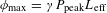
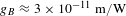 $g_{B}\approx 3\times 10^{-11}~\text{m}/\text{W}$
is the peak SBS gain coefficient[Reference Agrawal35],
$g_{B}\approx 3\times 10^{-11}~\text{m}/\text{W}$
is the peak SBS gain coefficient[Reference Agrawal35],
 $A_{\text{eff}}$
is the effective mode area,
$A_{\text{eff}}$
is the effective mode area,
 $\unicode[STIX]{x0394}\unicode[STIX]{x1D708}_{L}$
is the linewidth of the signal laser (has a value of 179.8 MHz as shown in Figure 9) ,
$\unicode[STIX]{x0394}\unicode[STIX]{x1D708}_{L}$
is the linewidth of the signal laser (has a value of 179.8 MHz as shown in Figure 9) ,
 $\unicode[STIX]{x0394}\unicode[STIX]{x1D708}_{B}\approx 40~\text{MHz}$
is the linewidth of the SBS gain spectrum[Reference Rothenberg, Thielen, Wickham and Asman37],
$\unicode[STIX]{x0394}\unicode[STIX]{x1D708}_{B}\approx 40~\text{MHz}$
is the linewidth of the SBS gain spectrum[Reference Rothenberg, Thielen, Wickham and Asman37],
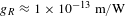
 $G\approx 466/10=46.6$
is the linear amplification factor of the main amplifier and
$G\approx 466/10=46.6$
is the linear amplification factor of the main amplifier and
 $L_{\text{overlap}}$
is the interaction fiber length[Reference Su, Zhou, Wang, Lü and Xu38]:
$L_{\text{overlap}}$
is the interaction fiber length[Reference Su, Zhou, Wang, Lü and Xu38]:
 $$\begin{eqnarray}\displaystyle & & \displaystyle L_{\text{overlap}}=\nonumber\\ \displaystyle & & \displaystyle \left\{\begin{array}{@{}l@{}}\min \left(L,\displaystyle \frac{ct_{p}}{2n}\right),\hspace{116.39996pt}L\leqslant Tc/2n,\\ \left(\left\langle \displaystyle \frac{2nL}{cT}\right\rangle -1\right)\times \displaystyle \frac{ct_{p}}{2n}\\[12.0pt] \,+\min \left[\!\displaystyle \frac{ct_{p}}{2n},L-\displaystyle \frac{1}{2}\left(\left\langle \displaystyle \frac{2nL}{cT}\right\rangle -1\right)\!\left(\displaystyle \frac{Tc}{n}\right)\!\right],\,\,L>Tc/2n,\end{array}\right.\hspace{-10.00002pt}\nonumber\\ \displaystyle & & \displaystyle\end{eqnarray}$$
where
 $c\approx 3\times 10^{8}~\text{m}/\text{s}$
is the optical velocity in vacuum,
$c\approx 3\times 10^{8}~\text{m}/\text{s}$
is the optical velocity in vacuum,
 $L$
is the fiber length,
$L$
is the fiber length,
 $t_{p}$
is the pulse duration,
$t_{p}$
is the pulse duration,
 $n\approx 1.45$
is the optical refractive index of the fiber core and
$n\approx 1.45$
is the optical refractive index of the fiber core and
 $T$
is the pulse period. As a result, the calculated peak SBS threshold is
$T$
is the pulse period. As a result, the calculated peak SBS threshold is
 ${\sim}$
10.95 kW, which is a little higher than present peak power. The peak SRS threshold can be estimated to be
${\sim}$
10.95 kW, which is a little higher than present peak power. The peak SRS threshold can be estimated to be
 ${\sim}$
27.2 kW according to the formula
${\sim}$
27.2 kW according to the formula
 $P_{\text{SRS-peak}}=16A_{\text{eff}}/g_{R}L_{\text{eff}}$
[Reference Agrawal35], where
$P_{\text{SRS-peak}}=16A_{\text{eff}}/g_{R}L_{\text{eff}}$
[Reference Agrawal35], where
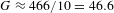
 $g_{R}\approx 1\times 10^{-13}~\text{m}/\text{W}$
is the Raman gain coefficient,
$g_{R}\approx 1\times 10^{-13}~\text{m}/\text{W}$
is the Raman gain coefficient,
 $A_{\text{eff}}$
is the effective mode area and
$A_{\text{eff}}$
is the effective mode area and
 $L_{\text{eff}}$
is the effective fiber length. This estimated value is far higher than present output peak power, so the SRS could not be the limitation factor for further power scaling but the SBS threshold may be reached firstly as the output power increases a little further.
$L_{\text{eff}}$
is the effective fiber length. This estimated value is far higher than present output peak power, so the SRS could not be the limitation factor for further power scaling but the SBS threshold may be reached firstly as the output power increases a little further.
Figure 9 shows the scanning spectra of the 3rd pre-amplifier and the main amplifier at the maximal output power. Due to nonlinear effect such as self-phase modulation (SPM), the linewidth of the maximal output power is broadened to be
 ${\sim}$
203.6 MHz, with an increase of
${\sim}$
203.6 MHz, with an increase of
 ${\sim}$
23.8 MHz compared with the 3rd pre-amplifier. There is an empirical formula,
${\sim}$
23.8 MHz compared with the 3rd pre-amplifier. There is an empirical formula,
 $\unicode[STIX]{x1D6FF}\unicode[STIX]{x1D714}=0.86\unicode[STIX]{x0394}\unicode[STIX]{x1D714}_{0}\unicode[STIX]{x1D719}_{\text{max}}$
, which can be used to estimate the broadened linewidth of the main amplifier. The
$\unicode[STIX]{x1D6FF}\unicode[STIX]{x1D714}=0.86\unicode[STIX]{x0394}\unicode[STIX]{x1D714}_{0}\unicode[STIX]{x1D719}_{\text{max}}$
, which can be used to estimate the broadened linewidth of the main amplifier. The
 $\unicode[STIX]{x0394}\unicode[STIX]{x1D714}_{0}$
is the initial spectral linewidth, i.e., the linewidth of the 3rd pre-amplifier.
$\unicode[STIX]{x0394}\unicode[STIX]{x1D714}_{0}$
is the initial spectral linewidth, i.e., the linewidth of the 3rd pre-amplifier.
 $\unicode[STIX]{x1D719}_{\text{max}}=\unicode[STIX]{x1D6FE}P_{\text{peak}}L_{\text{eff}}$
is the maximal phase shift in the main amplifier, where
$\unicode[STIX]{x1D719}_{\text{max}}=\unicode[STIX]{x1D6FE}P_{\text{peak}}L_{\text{eff}}$
is the maximal phase shift in the main amplifier, where
 $P_{\text{peak}}$
is the peak power,
$P_{\text{peak}}$
is the peak power,
 $\unicode[STIX]{x1D6FE}=n_{2}\unicode[STIX]{x1D714}_{0}/cA_{\text{eff}}$
is the nonlinear parameter, and
$\unicode[STIX]{x1D6FE}=n_{2}\unicode[STIX]{x1D714}_{0}/cA_{\text{eff}}$
is the nonlinear parameter, and
 $n_{\text{2}}$
has a value of
$n_{\text{2}}$
has a value of
 $2.6\times 10^{-20}$
[Reference Agrawal35]. By the calculation,
$2.6\times 10^{-20}$
[Reference Agrawal35]. By the calculation,
 $\unicode[STIX]{x1D6FF}\unicode[STIX]{x1D714}=1.09\unicode[STIX]{x0394}\unicode[STIX]{x1D714}_{0}$
, so the broadened linewidth of the main amplifier is about 195.3 MHz in theory, which is close to the experimental result.
$\unicode[STIX]{x1D6FF}\unicode[STIX]{x1D714}=1.09\unicode[STIX]{x0394}\unicode[STIX]{x1D714}_{0}$
, so the broadened linewidth of the main amplifier is about 195.3 MHz in theory, which is close to the experimental result.

Figure 9. The scanning spectra of (a) the 3rd pre-amplifier and (b) the main amplifier at the maximal output power.
To evaluate the polarization property of the pulse laser, the polarization degree (PD) during the power scaling process is measured based on the system consisting of a collimator, a
 $\unicode[STIX]{x1D706}/4$
waveplate and a polarization beam splitter. The PD is defined as
$\unicode[STIX]{x1D706}/4$
waveplate and a polarization beam splitter. The PD is defined as
 $P_{1}/(P_{2}+P_{2})$
, where
$P_{1}/(P_{2}+P_{2})$
, where
 $P_{1}$
is the power of the main polarization state and
$P_{1}$
is the power of the main polarization state and
 $P_{2}$
is the power of another orthogonal state. As shown in Figure 10, the PD is maintained around 90% in the whole power scaling process. At the maximal output power, the PD is
$P_{2}$
is the power of another orthogonal state. As shown in Figure 10, the PD is maintained around 90% in the whole power scaling process. At the maximal output power, the PD is
 ${\sim}$
90%, which is not high enough and may be attributed to the unavoidable offset at the splicing points. Meanwhile, the degradation of PD is accumulated as the number of the splicing points increases in the whole chain. The PD may be improved further if we monitor and optimize it in real time before constructing each stage amplifier. The slight instability of PD during the amplification may be attributed to the birefringence perturbation induced by the change of the thermal load and the cooling situation with the pump power increased.
${\sim}$
90%, which is not high enough and may be attributed to the unavoidable offset at the splicing points. Meanwhile, the degradation of PD is accumulated as the number of the splicing points increases in the whole chain. The PD may be improved further if we monitor and optimize it in real time before constructing each stage amplifier. The slight instability of PD during the amplification may be attributed to the birefringence perturbation induced by the change of the thermal load and the cooling situation with the pump power increased.

Figure 10. The polarization degree (PD) during the power scaling process of the main amplifier.
Based on the collimated beam, the beam quality is also measured. At the output power of 442 W, the
 $M^{2}$
is measured to be 1.32 by a beam quality analyzer, indicating a near-diffraction-limited beam quality, as shown in Figure 11(a). When reaching the maximal output power of 466 W with the pump limited, the
$M^{2}$
is measured to be 1.32 by a beam quality analyzer, indicating a near-diffraction-limited beam quality, as shown in Figure 11(a). When reaching the maximal output power of 466 W with the pump limited, the
 $M^{2}$
degrades to be 1.78 rapidly. It is inferred that the degradation of beam quality is induced by the MI[Reference Eidam, Wirth, Jauregui, Stutzki, Jansen, Otto, Schmidt, Schreiber, Limpert and Tunnermann39].
$M^{2}$
degrades to be 1.78 rapidly. It is inferred that the degradation of beam quality is induced by the MI[Reference Eidam, Wirth, Jauregui, Stutzki, Jansen, Otto, Schmidt, Schreiber, Limpert and Tunnermann39].
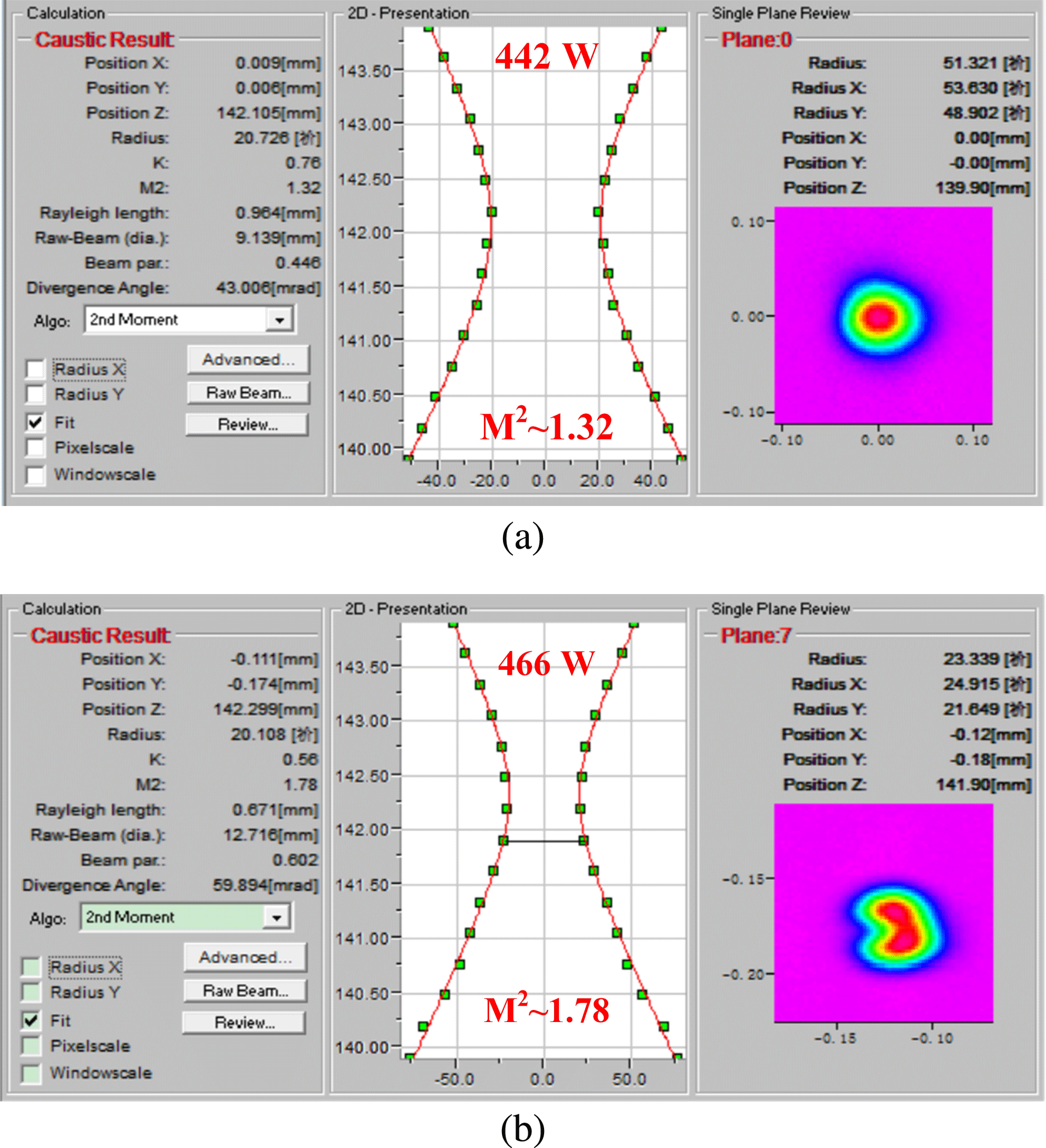
Figure 11. The beam quality at the output power of (a) 442 W and (b) the maximal power.
Because the response frequency of the CCD in the beam quality analyzer is too slow to respond the dynamic change of the beam profile when the MI occurs, a beam profile analyzer with relatively higher response frequency is used to capture the MI-induced beam degradation. As shown in Figure 12, at the maximal output power, the beam profile varies over time, which is a typical feature of the MI[Reference Eidam, Wirth, Jauregui, Stutzki, Jansen, Otto, Schmidt, Schreiber, Limpert and Tunnermann39, Reference Tao, Ma, Wang, Zhou and Liu40]. Nonetheless, in spite of the MI, the increasing trend of the output power does not change obviously due to the relatively large mode area of the active fiber which can sufficiently confine multiple modes, as demonstrated above. Remaining the rest of the system unchanged, the MI threshold may be improved further by changing the pump direction if the backward signal/pump combiner is available[Reference Tao, Ma, Wang, Zhou and Liu41, Reference Shi, Su, Zhang, Yang, Wang, Zhou, Xu and Lu42].

Figure 12. The six random samples of beam profile at the maximal output power captured by a beam profile analyzer with a sampling frequency of 30 Hz.
4 Conclusions
An all-fiberized high-average-power narrow linewidth ns pulsed fiber laser with linear polarization and near-diffraction-limited beam quality is demonstrated, based on a MOPA configuration. By adopting a high doping concentration PM LMA fiber with short length, combined with narrow pulse duration, the SBS and SRS are suppressed effectively. A maximal output power of 466 W is obtained with a narrow linewidth of 203.6 MHz. The pulse duration and repetition frequency are 4 ns and 10 MHz, respectively, corresponding to a peak power of 8.8 kW and a pulse energy of
 $46.6~\unicode[STIX]{x03BC}\text{J}$
. The polarization degree is around 90% during the power amplification. Near-diffraction-limited beam quality with an
$46.6~\unicode[STIX]{x03BC}\text{J}$
. The polarization degree is around 90% during the power amplification. Near-diffraction-limited beam quality with an
 $M^{2}$
factor of 1.32 is obtained at the output power of 442 W and the MI is observed at the maximal output power. To the best of our knowledge, this is the highest average output power of the all-fiberized narrow linewidth ns pulsed fiber laser with linear polarization and high beam quality, which is a promising source for the nonlinear frequency conversion, laser lidar and so on. Further power scaling is achievable in case of more available pump source if the MI is effectively suppressed.
$M^{2}$
factor of 1.32 is obtained at the output power of 442 W and the MI is observed at the maximal output power. To the best of our knowledge, this is the highest average output power of the all-fiberized narrow linewidth ns pulsed fiber laser with linear polarization and high beam quality, which is a promising source for the nonlinear frequency conversion, laser lidar and so on. Further power scaling is achievable in case of more available pump source if the MI is effectively suppressed.
Acknowledgements
This work is supported by the National Key Research and Development Program of China (No. 2017YFF0104603), in part by the Huo Ying-Dong Education Foundation of China (No. 151062), in part by the National Natural Science Foundation of China (Nos. 61705264 and 61705265), and in part by the Postgraduate Research and Innovation Project of Hunan Province (No. CX2016B031).


 Open access