


Abstract
A simple Peltier cooled cold trap aperture is presented to minimize the flux of hydrocarbons on optics in vacuum UV systems. The system can be cooled down to −40 °C under vacuum. To test the effect of the cold trap, the aperture is placed in front of a high-intensity D2 lamp used for calibration in the range of 116 nm to 300 nm which is flanged to a VUV spectrometer. The influence of the aperture temperature is monitored by measuring the intensity loss rate of the Lyman-alpha emission line at 121.6 nm due to the formation of carbon contamination on the MgF2 window of the lamp depending on the Peltier temperature. The application of the aperture significantly reduced the intensity loss from approx. 20% h−1 to less than 2% h−1 and enables the reliable use of a D2 lamp for the relative intensity calibration of the spectrometer.
Export citation and abstract BibTeX RIS
1. Introduction
Hydrocarbons are a permanent component of the background gas even in very clean, high vacuum systems like synchrotrons or spacecrafts due to the outgassing from chamber walls or other components in the system [1, 2]. Unfortunately, high-energy photons in the vacuum ultraviolet (VUV) range and shorter wavelengths are able to crack hydrocarbons resulting in carbon layers on windows, mirrors, and gratings of VUV systems (e.g. spectrometers). The carbon layer starts to absorb and scatter radiation at around 160 nm and the effect increases towards lower wavelengths [2–4]. The formed layers can be a severe source of error in optical emission spectroscopy (OES) of plasmas for measurements in the range of 50 nm to 160 nm where many intense lines of typical process gases (Ar, H, N, O) are present but also molecular (H2, N2) or excimer (He, Ar) emission. The photons emitted in this range can significantly influence plasma processes due to their high energy of 8 eV to 25 eV. Furthermore, most atomic lines are resonance lines to the ground state of the species yielding the possibility to be used in collisional-radiative models for state density determination. However, the most critical part is the calibration of VUV spectrometers in relative or even absolute units. Here, the only feasible calibration light sources are D2 lamps due to their broadband emission from 116 nm to 400 nm as well as their high stability [5, 6]. Unfortunately, the formation of the carbon layer is directly connected to the photon flux which is very high right after the sealing MgF2 window of the lamp and decreases with  with distance. Thus, if a similar hydrocarbon content is assumed in the whole system, the dominant formation of a carbon layer will be on the MgF2 window of the D2 lamp while the formation on other optics like mirrors or gratings is several orders of magnitude lower due to the reduced photon flux at large distances. Depending on the hydrocarbon content in the system and the lamp intensity, the photon flux of the lamp can be easily reduced by a factor of 2 or more per hour due to the formation of the carbon film. As a result, the calibration procedure can be massively falsified due to the change in the emitted spectrum of the calibrated D2 lamp and needs to be addressed. The Physikalisch-Technische Bundesanstalt (PTB), Berlin, Germany, calibrates radiometric standards in absolute units from 7 nm to 400 nm at the new electron storage ring Metrology Light Source (MLS) [7, 8]. In the case of D2 lamps a nitrogen cooled trap aperture is placed just in front of the MgF2 window reducing the hydrocarbon flux and minimizing the intensity reduction. Furthermore, the outside of the MgF2 window is polished before each measurement to remove the formed carbon layer resulting in a reproducability of D2 lamps of better than 2% over a time scale of more than 16 years [9]. This also indicates that the inside of the MgF2 window of the D2 lamps is not affected by the formation of hydrocarbons during measurements if sealed lamps are used like the ones from Cathodeon (now Heraeus) or Hamamatsu. However, D2 lamps calibrated at the PTB are run for 70 h before the calibration is performed to condition the lamp and achieve a high stability. During this procedure, it is very likely that nearly all of the residual hydrocarbons in the D2 lamp system are cracked and form a constant layer. However, this does not cancel out the possibility of hydrocarbons being released by other parts of the lamp, but the measurements in [9] indicate that this is not a significant issue.
While cleaning the MgF2 is rather simple (see below), the use of a liquid nitrogen operated cold trap aperture can be expensive or impossible due to the liquid nitrogen availability as well as inconvenient if the liquid nitrogen reservoir is not checked regularly and condensed particles on the cold trap evaporate due to the lack of cooling. Contamination analysis from scanning electron microscopy and electron probe microanalysis suggest that the carbon contamination can be significantly reduced already at temperatures below −20° [10, 11]. In this temperature range, the use of electronic Peltier elements can be easily realised and would significantly simplify the protection of the calibration standard and other optical elements in VUV systems. In this technical note, a simple Peltier cooled cold trap aperture is presented and tested. The performance is evaluated depending on the cold trap temperature down to −40 °C by measuring the temporal evolution of the Lyman alpha intensity of a high stability D2 lamp also used as secondary standard. Afterwards, the applicability of the aperture is evaluated by determining the relative efficiency of a VUV spectrometer using the cold trap aperture and benchmarking it at a characterized low-pressure plasma discharge.
2. Design of the Peltier cooled cold trap aperture
The design of the used cold trap aperture is depicted in figure 1 and the CAD file can be found in the supplementary information (stacks.iop.org/MST/31/077002/mmedia). A copper block (84 mm × 44 mm × 15 mm) is cooled by four Peltier elements (Tru Components TEC 2-127-63-04) from two sides. Two Peltier elements are cooled by a water cooled heat sink with copper cooling channels (Austerlitz electronic GmbH FK80.11, 80 mm × 45 mm × 15 mm), respectively. For an optimized heat transfer, heat-conducting paste is used between the copper plate and the Peltier elements (Thermal Grizzly Kryonaut) as well as between the Peltier elements and the heat sinks (Arctic MX-4). Two different types are used as standard heat-conduction pastes are not designed for −0 °C and might change their performance. However, as the Thermal Grizzly Kryonaut is very expensive, it is only used where necessary. All elements are fixed by two plastic frames connected with four threaded rods ensuring a tight connection for high thermal conductivity. The temperature of the copper block is measured using a resistance thermometer PT100 sensor (Heraeus Nexensos TO92) and the heat sink temperature using a negative temperature coefficient thermistor (NTC) sensor (Honeywell 6655–99 580 003). For cooling the copper aperture in front of the D2 lamp, an 8 mm copper rod with an M5 thread is connected to the copper block and to a vacuum feed-through. The feed-through consists of an aluminum part with KF16 flange, two viton O-rings (8 mm × 2 mm), and an O-ring spacer and a pressing at the top made from polyoxymethylene (POM). Only the O-rings are in contact with the copper rod to minimize any thermal flux. The copper parts at atmospheric pressure are insulated (K-Flex insulation, 19 mm) against thermal losses and condensation of water. The copper aperture is attached to the copper rod and tightened with an M1.6 screw. Its dimensions are chosen to exhibit a distance to the wall of 1 mm and not to limit the field of view of the spectrometer. The Peltier elements are controlled by a Peltier controller (Meerstetter Engineering TEC-1090) with a bipolar DC current source (max.±16 A, max.±30 V), two temperature monitoring inputs, and a PID control for regulating the temperature better than 0.1 °C. In operation, the controller changes the temperature of the copper block with 0.1 °C s−1. However, below −30 °C the rate is slightly reduced as the controller runs into the current limit of 3 A per Peltier element (70% of the maximum Peltier element current where, as a rule of thumb, the efficiency of the Peltier element drops significantly). At −40 °C using cooling water of 12 °C, the Peltier elements run at around 8 A and 64 W for several hours. The heat sink temperature is around 15 °C yielding a temperature gradient across the Peltier elements of ΔT = 55 °C and a cooling capacity of the Peltier elements of approx. 20 W. The exact temperature at the copper aperture is not known. However, any connection to elements with high thermal conductivity are avoided and simulations of a similar cold trap suggest only a small temperature difference of the aperture and the copper block [12]. Therefore, we assume a maximum temperature difference of 5 °C.
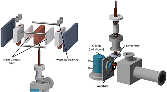
Figure 1. Left: Drawing of the upper part ('air-side') of the Peltier cold trap showing the copper block, the four Peltier elements, the water cooled aluminum heat sinks as well as the copper rod to the vacuum feed-through. Right: Drawing of the vacuum part of the cold trap aperture: the vacuum feed-through with two sealing rings, a plastic spacer, and and a plastic compression part. The rod is connected to the aperture just in front of the MgF2 window of the D2 lamp which is flanged to the vacuum with a sealing ring pressed around the lamp nose.
Download figure:
Standard image High-resolution image3. VUV setup
To test the effect of the Peltier cooled cold trap aperture, the system is connected to a VUV spectrometer. The double monochromator (Horiba Scientific DH30UVLSP) consists of two single monochromators (Horiba Scientific H30UVL) with two toroidal replica gratings (1200 grooves mm−1, Al-MgF2 coated, optimized for 121 nm) and a spectral range of 50 nm–300 nm. The spectrometer is pumped with a turbo pump (Leybold Turbovac 350i) and a scroll pump (Leybold Scrollvac SC 5 D). Two pressure gauges are used (Leybold Penningvac PTR90N, Leybold Ceravac CTR100N) and the system can be flushed with Ar 6.0 up to atmospheric pressure. The detector is a photomulitplier tube (PMT) (Hamamatsu R6836) with a sensitivity range of 116 nm–320 nm, equipped with a photon counting socket (Hamamatsu E990-08), a photon pulse digitizer (Hamamatsu C9744), a counting unit (Hamamatsu C8855-01) and is powered at 950 V by a stabilized power supply (Hamamatsu C9525-51). The calibration plane of the system is defined by a 1.6 mm circular aperture which is focused on the entrance slit using a concave mirror and a flat mirror. The mirror substrates (convace: OptoSigma TCBS-25C05-400, 25 mm diameter, 200 mm focal point; flat: OptoSigma OFBP-25C05-20, 25 mm diameter) are coated with 40 nm platinum layer (Carl Zeiss SMT GmbH), mounted in vacuum mirror mounts (Newport 9817-6-NI-K-V), and placed in a vacuum chamber (ISO-K 200) with self-made vacuum feedthroughs for fine tuning of the mirror mounts. The distance between the 1.6 mm aperture and the concave mirror is 750 mm with the flat mirror redirecting the light beam at 650 mm. Due to the deviation off the optical axis of 14°, the tangential focal point is located in 261, 8 mm distance to the concave mirror [13]. Here, the entrance slit of the spectrometer is placed to make use of the ellipsoidal image of the circular aperture and maximize the photon flux into the system. The chamber is equipped with a turbo pump (Leybold Turbovac 90i) and scroll pump (Leybold Scrollvac SC 5 D) and a pressure gauge (Leybold Penningvac PTR90N). The base pressure of the entire VUV system is 4.5 × 10⁻⁴ Pa. The light source is a D2 lamp with MgF2 window (Hamamatsu L9841, 300 mA, 87 V) emitting a broad band spectrum from 115 nm to 400 nm (cf. figure 3). The angle of acceptance of the optical system is 0.97° and the D2 lamp is placed at 236 mm distance to the circular aperture to capture the entire D2 discharge. The cold trap aperture is placed as close as possible to the D2 lamp to minimize the hydrocarbon flux on the MgF2 window.
4. Cleaning procedure of the D2 lamp
In order to apply the calibrated spectrum of the D2 lamp during the calibration procedure, the MgF2 window of the lamp has to be cleaned prior to mounting to the vacuum vessel to remove all carbon compounds and establish the same transmission as during the calibration at the primary standard [9]. Therefore, the window is polished with Al2O3 nanoparticles (Alfa Aesar Aluminum oxide (44 925), NanoArc AL-0450, 50% in H2O, colloidal dispersion with dispersant) using a cotton swab for 1 min and cleaned with ethanol (p.a.) afterwards. Figure 2 demonstrates the effect of this procedure by the intensity ratio of the measured spectra before and after polishing of a MgF2 window used for several years as separation window of a VUV spectrometer and low-pressure plasmas. The brownish deposit in the upper part cannot be removed with acetone or isopropanol and is the effect of the carbon contamination [3]. After polishing with Al2O3 45 nm nanoparticles, no deposition is visible anymore and the transmission of the window increased dramatically at wavelengths shorter than 160 nm to up to a factor of 30 around 121 nm. Thus, the calibration in the VUV using D2 lamps with MgF2 is only reasonable if the deposits are removed prior to every measurement.

Figure 2. Left: Intensity ratio of the measured spectra before and after polishing of a MgF2 window with Al2O3 nanoparticles and removing of the formed carbon layer. The merged picture depicts the circular carbon layer before and after cleaning. Right: Evolution of the intensity loss rate of the Lyman alpha emission line of the D2 lamp depending on the Peltier temperature.
Download figure:
Standard image High-resolution image5. Application of the cold trap aperture
The evolution of the intensity loss rate depending on the Peltier temperature is depicted in figure 2. The signal strength is in the range of 56.000 counts s−1 for all measurements. No pressure change was observed during the complete measurements and variation of the cold trap temperature which would indicate a change in the outgassing of materials or insufficient sealing due to the change of part dimension. At 10 °C the intensity decreases by approx. 20% h−1 due to the formation of the carbon layer on the MgF2 window of the D2 lamp. This rate strongly depends on the conditions and hydrocarbon content in the system and has been also observed to be in the range of 50% h−1. At lower temperature, the formation can be drastically decreased due to the condensation of the hydrocarbons on the cold trap aperture. In the used system, no difference between −30 °C and −40 °C is observable and in both cases the loss rate is reduced to approx. 1–2% h−1. Furthermore, the influence of other effects was excluded by observing that the measured intensity loss rate increased when the temperature of the aperture was risen step by step back to 10 °C. Sometimes a phenomenon was observed that after reaching −30 °C or −40 °C the intensity of the lamp signal slightly increased, then stayed constant for a few minutes, and then started to decrease continuously at the rate depicted in figure 2 for hours. The reason for this effect is not clear but might be connected to residual oxygen in the system or to surfaces getting into their temperature equilibrium in the presence of the cold trap aperture. The first is an effect known as UV-Ozone cleaning using oxygen radicals and UV-C emission [1, 3, 14]. The latter might change the outgassing and diffusion of hydrocarbons near the lamp and thereby change the deposition rate. However, the exact mechanisms is not known and might be investigated in the future.
Based on the measurements, the contamination of the MgF2 window of the D2 lamp in the VUV range cannot be avoided completely, but it can be reduced in a way that in practical terms nearly no intensity change occurs during the calibration measurements of the VUV spectrometer. Therefore, a reliable calibration of a VUV spectrometer should be possible as the intensity does not change during the repetitive measurement of the D2 lamp spectrum. Figure 3 depicts the mean spectrum of three spectra of the D2 lamp measured over a time scale of 90 min. The standard deviation in the range of 115 nm to 160 nm where the absorption of the carbon layers would occur is far less than 10% and demonstrates the applicability of the Peltier cold trap.
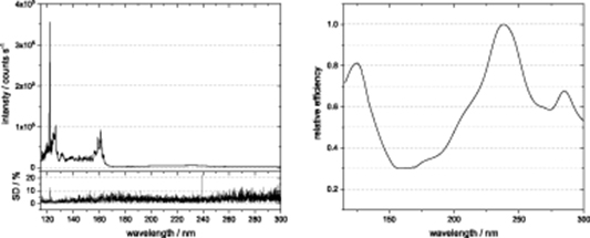
Figure 3. Left: Mean spectrum of the D2 lamp consisting of three single spectra measured in the presented system right after each other over a time scale of 90 min. The standard deviation in the range below 160 nm is far less than 10%. Right: Calculated relative efficiency of the VUV spectrometer determined with a D2 lamp calibrated in absolute units.
Download figure:
Standard image High-resolution image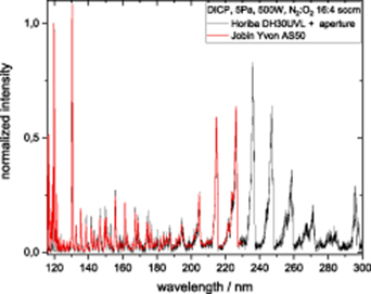
Figure 4. Comparison of the measurement of the presented Horiba DH30UVL spectrometer equipped with the cold trap aperture and the results of a previous measurement at a low-pressure plasma discharge at 5 Pa and N2:O2 atmosphere using an Jobin-Yvon AS50 monochromator.
Download figure:
Standard image High-resolution image
To test if the aperture is suitable for determining the relative efficiency of the system, the measured spectrum is compared to the reference spectrum of the PTB. However, this procedure cannot be applied by comparing each measured wavelength position directly because of two reasons. (1) For direct comparison the line shape of both systems has to be identical. The calibration of the PTB is performed with 800 pm FWHM (full width at half maximum), meaning a significant loss of resolution as well as a very large photon flux into the system, which might be problematic for the linearity of the PMT. (2) The spectrum of the D2 lamp consists of thousands of rotational lines below 170 nm (cf. figure 3) and even tiny deviations off the wavelength position lead to a significant change in intensity. Therefore, it is necessary to apply an averaging procedure over several lines to minimize the effect of wavelength deviations as well as perform the measurement with the desired resolution. This procedure is also applied by the PTB itself [7]. The calculated efficiency of the system shown in figure 3 is determined using a Gauss profile as weighting function at each wavelength position over a wavelength range of ±7.5 nm. The Gauss profile is defined in the way that 95% of the data is in this 15 nm range ( ). This method is comparable to a smoothing functions and can handle very strong intensity variations like the intense Lyman-alpha line at 121.6 nm surrounded by very weak lines or the changes in the 160 nm range. However, the smoothing is not too strong and does not lead to a loss of significant efficiency structures as was tested by applying different wavelength ranges. The resulting relative efficiency of the VUV spectrometer shows two reasonable maxima: one at around 121 nm where the maximum efficiency of the grating is present and at 240 nm where the maximum sensitivity of the PMT is located. For validation of the correctness of the whole procedure, the spectrometer is connected to a low-pressure setup which has been characterized in the VUV range before [15]. The comparison of the measured spectra of an N2:O2 plasma at 5 Pa between the VUV spectrometer equipped with the cold trap aperture and the previous measurements shows a very good agreement. Thus, the presented Peltier cooled cold trap can be used to ensure a reliable calibration of VUV spectrometer with D2 lamps by minimizing the hydrocarbon flux to the MgF2 window of the lamp and reducing the formation of the absorbing carbon layer.
6. Summary
The use of a Peltier cooled cold trap aperture at −40 °C can significantly reduce the hydrocarbon flux on the MgF2 window of a high-intensity D2 lamp and minimize the formation of a carbon film which drastically falsifies the measured signal. The presented setup lowered the intensity loss from approx. 20% h−1 at uncooled conditions to less than 2% h−1 at a Peltier temperature of −40 °C. Thus, reliable calibration measurements of VUV spectrometers with D2 lamps can be achieved without the need to cool cold traps with liquid nitrogen to reduce the fast formation of carbon layers. However, for correct calibration the D2 lamp window needs to polished prior to each measurement to ensure the same photon flux as during the initial calibration at the primary standard.
Acknowledgment
The authors thank Frederic Duschl for fruitful comments during the construction and manufacturing of the Peltier system as well as Rainer Thornagel and Wolfgang Paustian for several comments on the formation of the carbon layers on D2 lamps. This work was funded by the German Research Foundation (DFG) within the frame of the Collaborative Research Centre SFB-TR 87 (B4, C1).
Supplementary Material
Supplementary material for this article is available online