


1 Introduction
Mode-locked thulium-doped fiber lasers (TDFLs), which operate in the 2 μm spectral region with pulse duration ranging from nanoseconds to femtoseconds, have attracted a lot of interest due to their applications in mid-infrared supercontinuum generation, remote sensing, laser processing, medicine and free-space communication[Reference Leindecker, Marandi, Byer, Vodopyanov, Jiang, Hartl, Fermann and Schunemann1–Reference Rudy, Digonnet and Byer10]. In the 2 μm regime, research efforts associated with mode-locked fiber lasers so far have mainly aimed at ultra-short pulse (∼fs or ∼ps pulse) generation. The nanosecond-scale mode-locked pulses have received less attention. In effect, nanosecond pulses with high pulse energy have played an important role in many potential applications, such as laser cutting and welding, laser ablation for surface cleaning and as a pump source for mid-infrared pulse laser generation[Reference Chowdhury, Pal, Pal, Chatterjee, Paul, Sen and Pal11].
In general,  $Q$-switching and gain switching are two well-known techniques for nanosecond pulse generation. Usually, it is difficult for passively
  $Q$-switched fiber lasers to produce pulses with several nanoseconds duration owing to the limitation of cavity length and modulation depth of the saturable absorber (SA)[Reference Hakulinen and Okhotnikov12]. As for actively
  $Q$-switched fiber lasers, stable nanosecond pulses can be obtained. Nevertheless, a complex electronics controlling system is needed, which highly increases the complexity of the fiber laser. Gain-switched fiber laser is another alternative, but a high-energy pulse pump source is a challenge for 2 μm gain-switched pulse generation[Reference Jiang and Tayebati13 , Reference Dickinson, Jackson and King14]. Furthermore, compared with the mode-locked pulse, the
  $Q$-switched pulse and gain-switched pulse have poorer stability and cannot be reshaped since the phase of the pulse of
  $Q$-switching or gain switching is random.
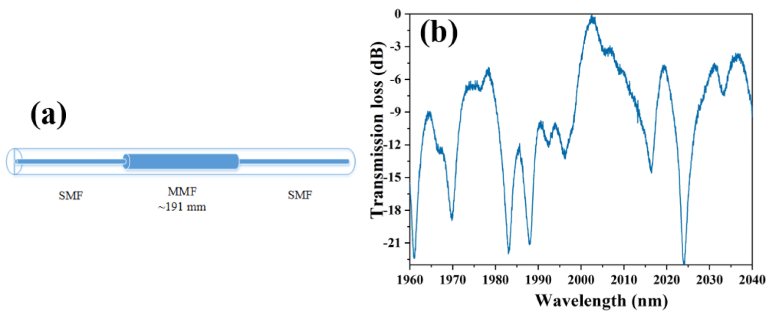
Figure 1. SMS fiber structure MMI: (a) structure configuration; (b) transmission characteristics[Reference Wang, Zhao, Huang, Lin and Ruan31].
In fact, passively mode-locked fiber lasers also can generate nanosecond pulses with high energy[Reference Wang, Wang, Zhao, Zhang, Zhang, Hu, Yang, Liu, Duan, Liu, Li, Shen, Sui and Liu15] in which dissipative soliton resonance (DSR) has been proved as an effective method. Chang et al. theoretically predicted that the DSR can be formed in the anomalous dispersion regime[Reference Chang, Soto-Crespo, Ankiewicz and Akhmediev16]. In the following year, the existence of high-energy nanosecond DSR pulses in long cavity passively mode-locked erbium-doped fiber lasers with anomalous dispersion was experimentally reported by Li et al. [Reference Li, Liu, Hu, Wang, Lu, Wang and Zhao17]. Relying on the nonlinear polarization rotation (NPR) technique, they obtained the output pulse energy of ∼79.5 nJ at a pulse repetition rate of ∼278 kHz, and the pulse duration could be tuned from ∼12.8 ns to ∼155.4 ns. After that, several works about DSR pulse generation in anomalous dispersion have been reported. Nevertheless, most of the works are focused on the 1.5 μm region[Reference Duan, Liu, Mao, Wang and Wang18–Reference Lee, Koo and Lee21]. As for the 2 μm region, there are a few reports about the nanosecond passively mode-locked fiber laser. In 2013, Fu et al. realized a passively mode-locked Tm, Ho-codoped fiber laser with a pulse duration of ∼122 ns and pulse energy of ∼35.2 nJ by utilizing graphene as an SA and lengthening the cavity to ∼213 m[Reference Fu, Gui, Li, Xiao, Zhu and Yang22]. Based on NPR and ∼460 m long cavity length, fundamental mode-locked pulses with a pulse duration of ∼304 ns were obtained by Wang et al. [Reference Wang, Zhou, Wang, Xiao and Liu23]. By adding a section of ∼40 m long single mode fiber (SMF) in a simple linear cavity TDFL, Liu et al. obtained self-mode-locked pulses with a pulse duration of ∼40 ns and pulse energy of ∼32.7 nJ[Reference Liu, Luo, Huang, Qu, Cheng, Wang, Wu, Xu and Cai24]. Recently, relying on a graphene SA and a narrow bandwidth fiber Bragg grating (FBG), Wang et al. realized a nanosecond-scale mode-locked TDFL with ∼54 m long cavity length, but the laser has a relatively low pulse energy of ∼1.5 nJ[Reference Wang, Zhang, Gao, Xia and Wu25]. In our previous work, by utilizing a nonlinear optical loop mirror (NOLM) and an F-P fiber interferometer with a ∼1000 m long cavity, stable pulses with pulse duration ranging from ∼2.4 ns to ∼21.2 ns and a maximum pulse energy of ∼1.5 μJ were obtained[Reference Wang, Huang, Yang, Zhang and Ruan26]. For DSR in the 2 μm region, Xu et al. reported a DSR TDFL with net normal dispersion[Reference Xu, Song, Du, Yan, Guo, Zheng and Ruan27]. Zhao et al. first reported a nanosecond DSR pulse in TDFL with anomalous dispersion based on nonlinear amplification loop mirror (NALM). With a figure-of-eight configuration resonator, the direct output pulse energy is ∼40.5 nJ[Reference Zhao, Ouyang, Zheng, Liu, Ren, Li, Ruan and Xie28]. With a figure-9 cavity configuration, Kharitonov et al. demonstrated a DSR mode-locked TDFL with an average output power of 670 mW and pulse energy of 400 nJ[Reference Kharitonov and Brès29]. The highest average output power of DSR from the TDFL oscillator is ∼1.4 W with pulse energy of ∼353 nJ, which was obtained by Du et al. with an NOLM-based mode-locked  $\unicode[STIX]{x1D70E}$-shaped cavity TDFL[Reference Du, Li, Ruan, Wang, Chen and Luo30]. Nevertheless, we noted that the high-energy DSR nanosecond pulses in the 2 μm region were almost based on the ‘artificial’ SAs, such as NOLM and NALM. There are a few experimental reports of ‘real’ SA-based DSR TDFL.
In this paper, we will present high pulse energy nanosecond-scale passively mode-locked TDFLs with semiconductor saturable absorbers (SESAs) and carbon nanotubes (CNTs). A stable rectangular-shape DSR pulse with a maximum pulse energy up to ∼0.14 μJ was first obtained in ‘real’ SA-based mode-locked TDFL. Moreover, our experimental results verified that the SMF-MMF-SMF (SMS, SMF: SMF-28, Corning; MMF: multimode fiber, AFS105/125Y) fiber structure multimode interferometer (MMI)[Reference Wang, Zhao, Huang, Lin and Ruan31, Reference Zhang, Hu, Wang and Feng32] can be used as an effective wavelength filter for mode-locked TDFL.
2 Experimental setup and result
In our experiment, the SMS fiber structure MMI filter was constructed by fusion splicing two pieces of SMFs at both ends of a section of ∼191 mm long MMF. The structure configuration and transmission characteristics of the fiber MMI are shown in Figures 1(a) and 1(b), respectively. The main transmission peak is at ∼2003 nm with a transmission loss of ∼0.5 dB, as shown in Figure 1(b).
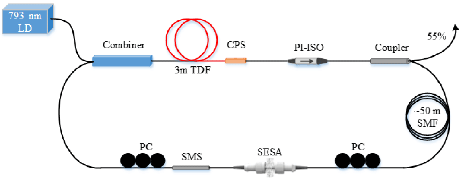
Figure 2. Schematic configuration of SESA-based nanosecond TDFL. LD, laser diode; PC, polarization controller; CPS, cladding power stripper; SMF, single mode fiber.
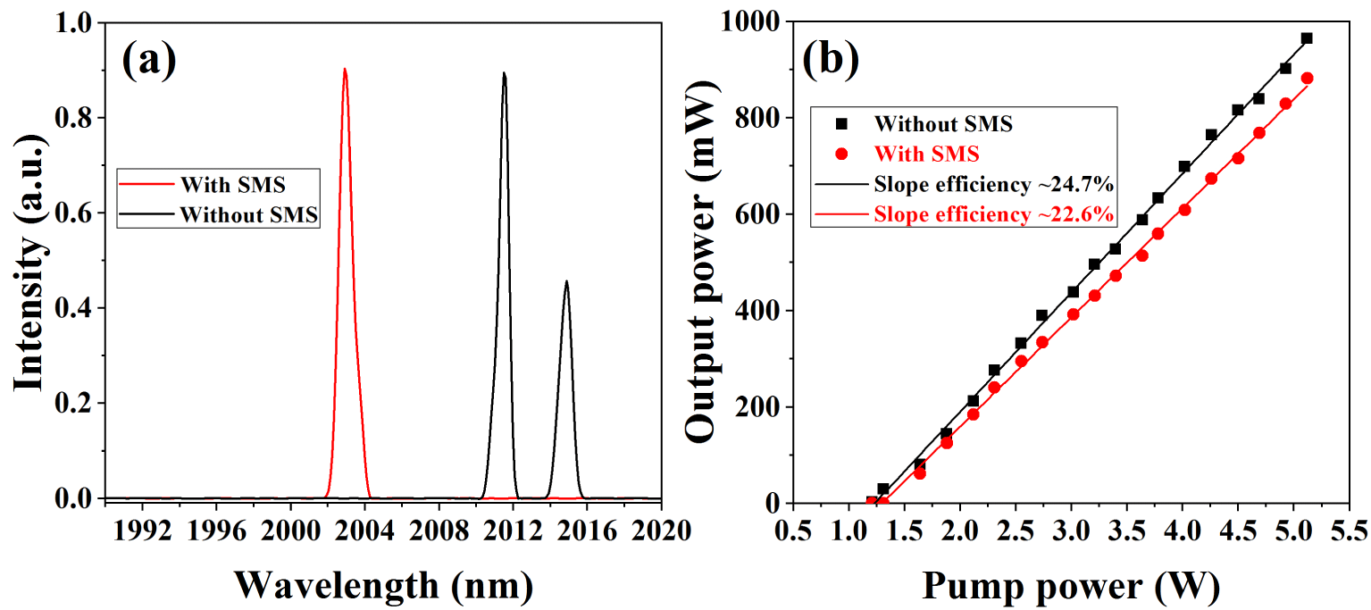
Figure 3. Output properties of the fiber laser without SA: (a) typical output spectra with and without the SMS fiber structure MMI; (b) output efficiencies of the fiber laser with and without the SMS fiber structure MMI.
2.1 SESA-based nanosecond mode-locked fiber laser
The experimental setup for an SESA-based nanosecond mode-locked TDFL is schematically shown in Figure 2. The gain fiber is a section of ∼3 m length single mode double-clad Tm-doped fiber (SM-TDF-10P/130-HE), which is pumped by a fiber-pigtailed 793 nm multimode laser diode (LD) with a maximum output power of ∼12 W via a  $(2+1)\times 1$ pump/signal combiner. The inner cladding diameter of the TDF is ∼130 μm with absorption of ∼3 dB/m at 793 nm. The unabsorbed pump light will effectively strip by a self-made cladding power stripper (CPS) behind the TDF. To ensure the unidirectional propagation of the laser in the cavity, a polarization independent optical isolator with insertion loss of ∼2.6 dB was used in the cavity. After the isolator, an optical coupler with an output ratio of ∼55% was used for laser outputting. The SESA and SMS fiber structure MMI were placed between two polarization controllers (PCs), which act as a mode locker and a wavelength selector, respectively. The SESA (SA-2000-25-10ps-x, BATOP) has the modulation depth, transmittance and saturation fluence of ∼15%, ∼74% and ∼2 mJ/cm2, respectively, at ∼2000 nm. The PCs are utilized to adjust the polarization state of the light and initiate the mode-locking. Moreover, a section of a ∼50 m long SMF was added into the cavity to manage the dispersion and implement the nanosecond mode-locked pulse. Thus, a simple ring cavity laser was formed with a total cavity length and a dispersion of ∼63.5 m and
  $-5.8~\text{ps}^{2}$, respectively.
In the beginning, to verify that the SMS fiber structure MMI can function as an available wavelength selector, the SESA was not inserted into the cavity. The output properties of the fiber laser with and without the SMS fiber structure MMI are shown in Figure 3. When the fiber MMI was inserted into the cavity, the lasing wavelength was ∼2003 nm and the output efficiency of the fiber laser only had a slight decrease (from ∼24.7% to ∼22.6%), which means the fiber MMI can be used as an effective wavelength selector. Moreover, no pulses were observed by increasing the pump power and fully manipulating the PCs, which verifies the fiber MMI is not responsible for mode-locking[Reference Chen, Zhang, Zhang, Li, Zhang and Xia33].

Figure 4. Typical mode-locked properties of the fiber laser at pump power of ∼2.83 W: (a), (b) mode-locked pulses; (c) output spectrum; (d) output RF spectra.
Then, the SESA was sandwiched between the FC/PC ferrules, and the threshold of the mode-locked operation was about ∼2.06 W. The typical mode-locked output properties at pump power of ∼2.83 W are exhibited in Figure 4. Stable mode-locked pulses are shown in Figures 4(a) and 4(b), which were measured by a photodetector (ET-5000, ∼28 ps rise/fall time) together with a 20 GS/s high-speed oscilloscope with 1-GHz bandwidth (Tektronix, DPO 7104C digital phosphor oscilloscope). The mode-locked pulses have a pulse duration of ∼2.4 ns with a rectangular shape, as shown in Figure 4(a). Since the response threshold of our detecting system is less than 1 ns, we confirm that the pulse durations are truly detected. In addition, we also measured the autocorrelation traces of the nanosecond pulses with a time span of 50 ps by a commercial autocorrelator (APE Pulsecheck). But no sub-pulse was observed, which further proves that the nanosecond mode-locked pulses do not have complicated ultra-short sub-pulses. Figure 4(c) shows the output spectrum of the mode-locked fiber laser. The central wavelength is ∼2002.9 nm with 3 dB bandwidth of ∼1.7 nm, corresponding to the transmission spectrum of the SMS fiber structure MMI. Thus the time-band product is ∼305, which indicates a serious chirp. With the spectrum analyzer (Agilent, E4407B), the radio-frequency (RF) spectra were measured and plotted in Figure 4(d). The repetition frequency of the mode-locked pulse is ∼3.254 MHz with a signal-to-noise ratio of ∼65 dB, which verifies that the laser operated at a stable fundamental frequency mode-locked state. The harmonic RF spectra with 300 MHz bandwidth are shown in the inset of Figure 4(d).

Figure 5. (a) Mode-locked pulse envelopes at different pump powers; (b) pulse duration versus pump power.
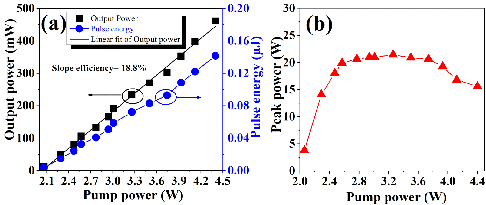
Figure 6. (a) Average output power and pulse energy variance with the pump power; (b) peak power variance with the pump power.
In the experiment, we noted that the mode-locked pulse duration was increased with the pump powers, and the details are shown in Figure 5. Figure 5(a) shows the evolution of the pulse envelopes. With the increasing pump power from ∼2.06 W to ∼4.40 W, the pulse duration was broadened from ∼949 ps to ∼9.2 ns, as given in Figure 5(b). Moreover, the average output powers of the mode-locked pulses were measured, and the corresponding pulse energies and peak powers were calculated, as depicted in Figure 6. The average output power increased linearly as the enhancement of the pump power with a slope efficiency of ∼18.8%. When the pump power reached ∼4.40 W, the maximum output power of ∼461 mW and pulse energy of ∼0.14 μJ were obtained. The corresponding peak powers of the pulses were calculated and shown in Figure 6(b). We noted that the pulse peak powers were approximately maintained at a stable value of ∼21 W, when the pump power was in the range of ∼2.57 W to ∼3.74 W. Similar results were reported in Refs. [Reference Krzempek20, Reference Zhao, Ouyang, Zheng, Liu, Ren, Li, Ruan and Xie28, Reference Mei, Chen, Xu, Zhang, Gu, Sun and Wang34], and the phenomenon was caused by the peak power clamping (PPC) effect. The decrease in the peak power at higher pump power was considered as the result of performance degrading of the SESA, since the high pulse energy will lead to a large heat accumulation at the SESA. The above characteristics of the mode-locked pulses, such as pulse duration increase with the pump power, nanosecond rectangular-shaped pulse and PPC effect, indicated that the mode-locked fiber laser operated in the DSR regime[Reference Li, Liu, Hu, Wang, Lu, Wang and Zhao17–Reference Lee, Koo and Lee21, Reference Zhao, Ouyang, Zheng, Liu, Ren, Li, Ruan and Xie28].
2.2 CNTs-PVA film based nanosecond mode-locked fiber laser
Similarly to the fiber laser configuration in Figure 2, the experimental setup of CNTs-based nanosecond mode-locked TDFL is shown in Figure 7. The laser output ratio is 45%, and a piece of ∼110 m long SMF was used for managing the dispersion and enhancing the nonlinearity. Thus, the total cavity length is ∼120 m and the dispersion is  ${\sim}-10.75~\text{ps}^{2}$. Through a typical balanced twin-detector method, the saturable absorber property of the CNTs-PVA film was measured and shown in Figure 8. The ultra-pulse light source is a mode-locked fiber laser with central wavelength, pulse duration and repetition rate of ∼1958 nm, ∼725 fs and ∼55 MHz, respectively. The CNTs-PVA film SA has a modulation depth of ∼23.7% and nonsaturable loss of ∼29.4%.
Table 1. Comparison of output properties of 2 μm nanosecond mode-locked fiber lasers
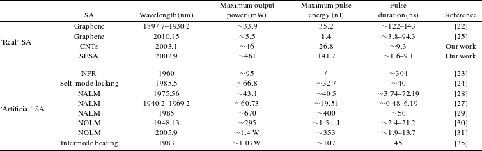
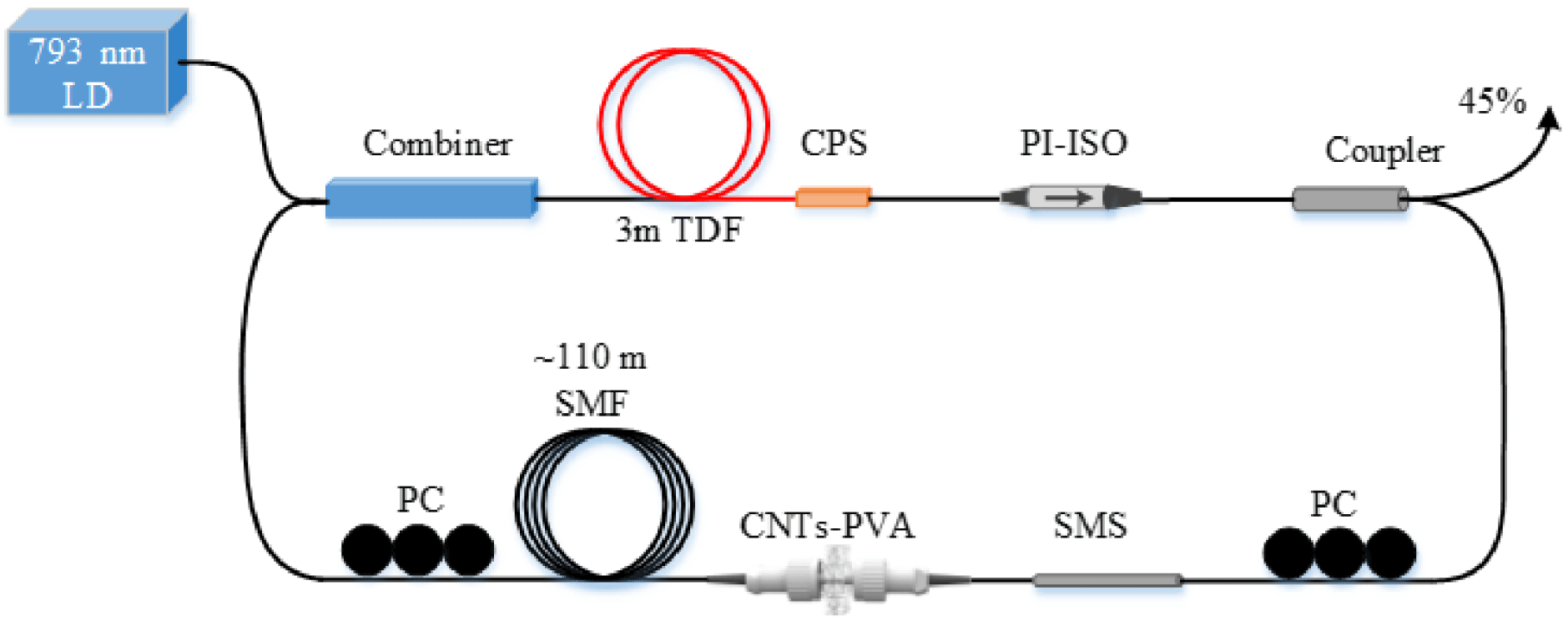
Figure 7. Schematic configuration of CNTs-PVA-based nanosecond TDFL.
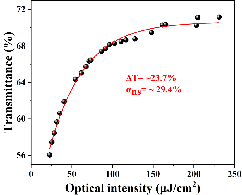
Figure 8. Saturable absorber properties of the CNTs-PVA.
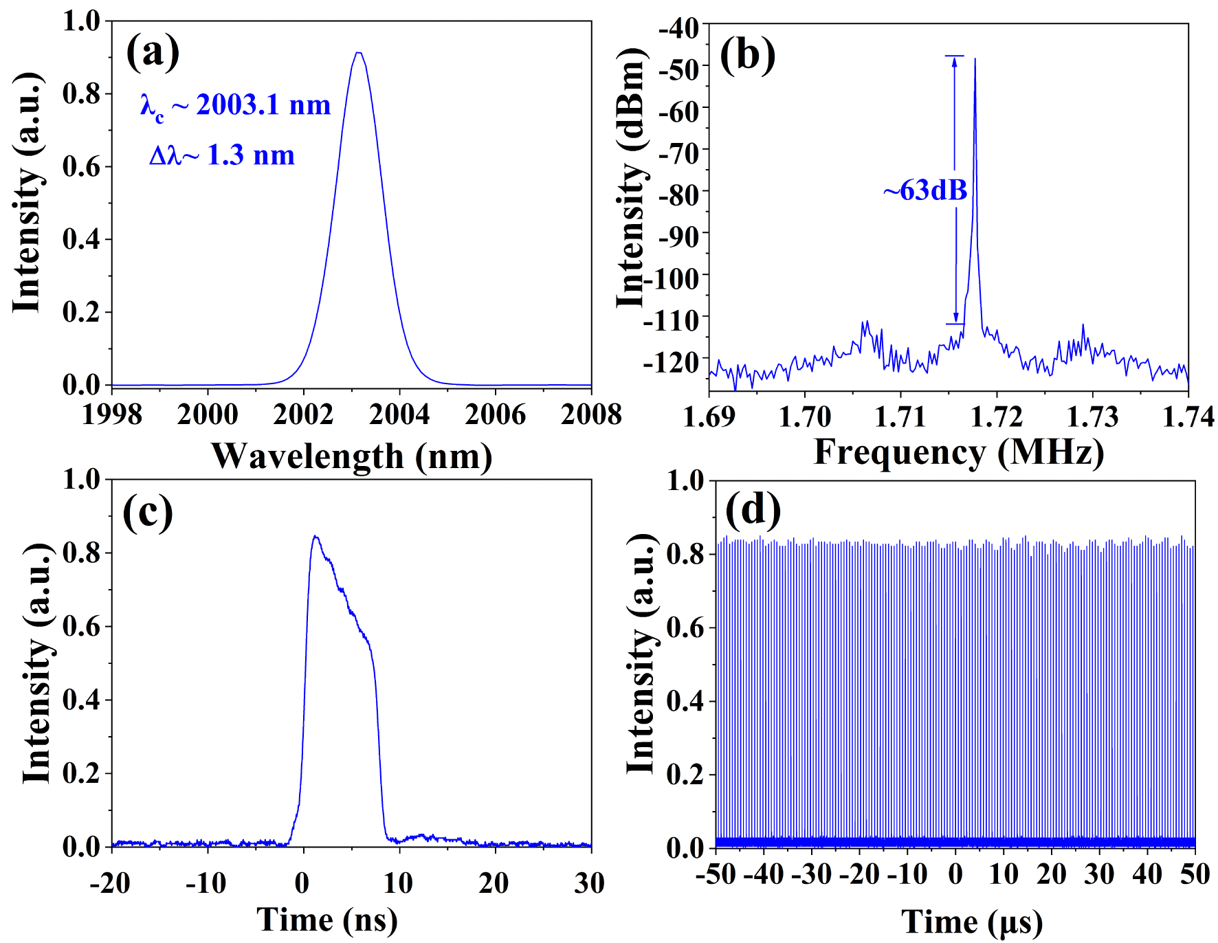
Figure 9. Typical mode-locking performance of the CNT-based fiber laser at pump power of ∼2.12 W: (a) output spectrum; (b) output RF spectrum; (c), (d) mode-locked pulses.
When the CNTs-PVA film was inserted into the cavity, with proper manipulation of the PCs, the initial mode-locked operation also could be obtained. Here, we characterized the mode-locking performance at the maximum pump power of ∼2.12 W, as shown in Figure 9. The mode-locked fiber laser centered at ∼2003.1 nm with 3 dB bandwidth of ∼1.3 nm, which depends on the transmission spectrum of the SMS fiber structure MMI, is shown in Figure 9(a). Figure 9(b) depicts the RF spectra. The repetition rate of the mode-locked pulse is ∼1.718 MHz and the signal-to-noise ratio is larger than 63 dB, which indicate a stable fundamental mode-locked operation. Figures 9(c) and 9(d) depict the mode-locked pulses. The single pulse duration of ∼9.3 ns with an approximate rectangular shape was measured. Together with the spectral width, the time-band product is ∼904. At a pump power of ∼2.12 W, the average output power of the fiber laser is ∼46 mW, corresponding to the pulse energy of ∼26.8 nJ.
In addition, Table 1 summarizes the representative output performances of all-fiberized nanosecond mode-locked TDFLs. In our experiment, the maximum average output power is ∼461 mW corresponding to the pulse energy of ∼141.7 nJ, which is higher than the previously reported results of ‘real’ SA-based nanosecond passively mode-locked TDFLs and comparable to the results of ‘artificial’ SA-based ones. However, owing to the relatively low damage threshold of the ‘real’ SA, the ‘real’ SA-based nanosecond mode-locked TDFLs still have the lower output power and pulse energy.
3 Conclusion
In summary, we have experimentally presented long cavity nanosecond-scale mode-locked fiber lasers with wavelength above 2 μm based on real SAs (SESA and CNTs) and SMS fiber structure MMI. The DSR pulse with output pulse energy up to ∼0.14 μJ was reported for the first time in real SA-based TDFL. This nanosecond mode-locked pulse with high pulse energy can be widely used in industrial processing and as a pump source for mid-infrared (∼3.5 μm) pulse laser generation after further amplification. Moreover, our experimental results verified the feasibility of SMS fiber structure MMI functioning as an effective wavelength filter in mode-locked TDFL.
Acknowledgement
This work was supported by the National Natural Science Foundation of China (NSFC) (No. 61575129).


 Open access