


1 Introduction
The high-power lasers used in the inertial confinement fusion (ICF) system worldwide need large KDP-type crystals as nonlinear crystals on account of their exceptional properties[Reference De Yoreo, Burnham and Whitman1–Reference Cai, Lin, Li, Lu, Hu and Zheng6]. The major limitation to growing such large KDP-type crystals by the traditional method is the slow growth rate, leading to a growth cycle of 1–2 years[Reference Wang, Li, Wang, Wang, Wang, Ding, Li, Shen, Liu and Huang7–Reference Li, Yu, Wang, Ding, Xu, Gu, Wang and Huang11]. Fortunately, the ‘point-seed’ rapid growth method was developed in the 1980s[Reference Zaitseva and Carman12, Reference Wang, Shen, Lan, Huang, Cui, Kang, Niu, Wang, Wang and Boughton13]. For the KDP-type crystals produced by the ‘point-seed’ rapid growth method, all prismatic faces and pyramidal faces develop under high supersaturated solutions[Reference Land, Martin, Potapenko, Palmore and De Yoreo14–Reference Pommies, Damiani, Bertussi, Capoulade, Piombini, Natoli and Mathis17]. In addition, a pyramid–prism (PY–PR) boundary is generated when different kinds of crystallographic faces are sewn together[Reference Chen, Wang, Wang, Bai, Xu, Li, Qi and Shao18–Reference Yan, Torres, Runkel, Woods, Hutcheon, Zaitseva and De Yoreo21]. By the orthogonal polarization interferometry technology,  $\unicode[STIX]{x0394}(n_{e}{-}n_{o})$ maps containing the PY–PR boundary were easily obtained, and the distortion near the PY–PR boundary was reported to be detrimental to efficient frequency tripling and phase matching[Reference Li, Zheng, Qi, Yin, Tang, Li, Xu, Lei, Lin, Zhang, Lu, Ma, He and Yao22, Reference Auerbach, Wegner, Couture, Eimerl, Hibbard, Milam and Hackel23]. More recently, a cuboid DKDP crystal was rapidly grown[Reference Chen, Wang, Wang, Zheng, Zhang, Qi and Shao24]. Without a pyramidal sector, the cuboid DKDP crystal had high cutting efficiency to obtain third harmonic generation (THG)-oriented samples for ICF. However, in practice, it is not always easy to get a long seed to grow a large cuboid KDP-type crystal. Therefore, it is of practical significance to reduce the length of the seed while maintaining the advantages of the cuboid KDP-type crystal.
In this study, a long-seed KDP crystal was rapidly grown. With almost the same high cutting efficiency to obtain THG-oriented samples, this long-seed KDP-type crystal can grow from a seed that is shorter than that of the cuboid KDP-type crystal. Then the crystalline quality, transmittance performance, laser-induced damage (LID) property and LID morphology of the long-seed KDP crystal were investigated.
2 Experimental setup
2.1 Crystal growth
The long-seed KDP crystal was rapidly grown in a self-developed 2000 L growth apparatus configured as an efficient continuous filtration system (CFS)[Reference Xie, Qi, Wang, Wang, Chen and Shao25, Reference Hu, Wang, Chang, Xie, Zhao, Qi and Shao26]. A long KDP seed with size  $20~\text{mm}\times 20~\text{mm}\times 260~\text{mm}$ was fixed on a crystal carrier, and the length direction of the seed crystal was the [001] crystallography direction. During crystal growth, the supersaturation of the solution was approximately 5%, and the crystal carrier was rotated in alternative cycles[Reference Robey and Maynes27, Reference Robey28]. After 70 days, a long-seed KDP crystal with dimensions
  $471~\text{mm}\times 480~\text{mm}\times 400~\text{mm}$ and weight 254 kg was grown, as shown in Figure 1. It is worth mentioning that there is no visible defect in the long-seed KDP crystal. In addition, the growth of a long-seed DKDP crystal is currently under way.
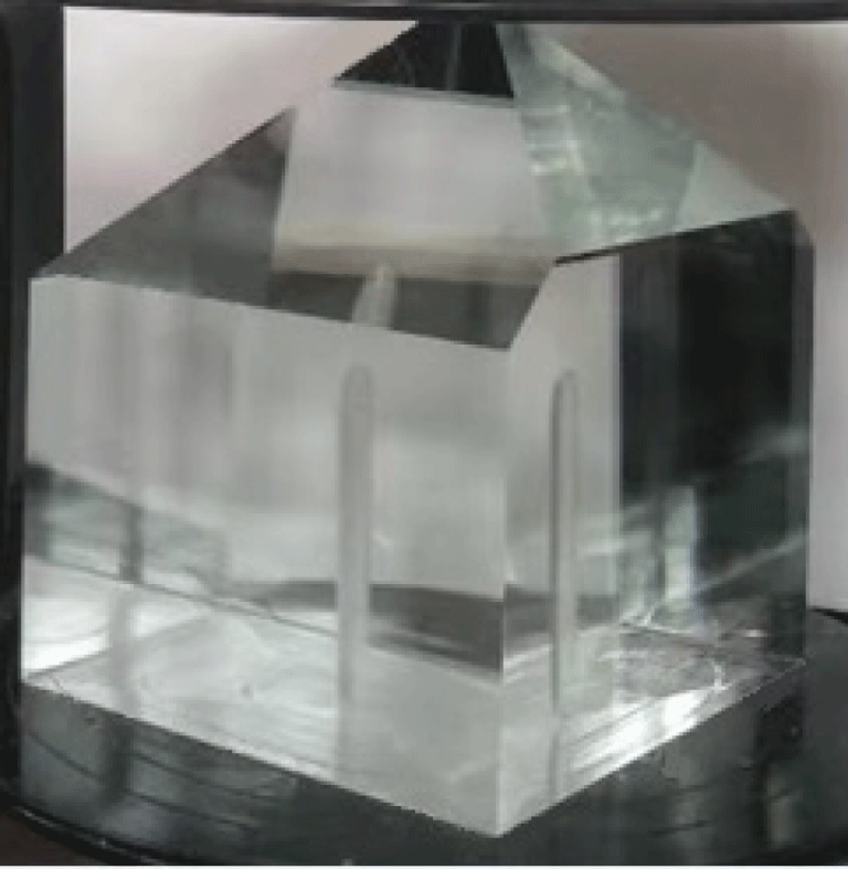
Figure 1. Long-seed KDP crystal with size  $471~\text{mm}\times 480~\text{mm}\times 400~\text{mm}$.
2.2 Characterization techniques
To evaluate the properties of the long-seed KDP crystal, the high-resolution X-ray diffraction (HRXRD) of an X-cut sample from this crystal was carried out[Reference Sharma, Verma, Singh and Bartwal29]. The transmission spectrum of a THG-oriented sample cut from the long-seed KDP crystal was tested using a Lambda 1050 spectrometer[Reference Chen, Wang, Wang, Bai, Xu, Li, Qi and Shao18]. The LID threshold (LIDT) at 355 nm of the THG-oriented sample was investigated under a Nd:YAG laser[Reference Peng, Zhao, Wang, Hu, Yang and Shao30]. The LID scattering image of the THG-oriented sample was captured by an online microscope system mounted on the laser damage facility, and the morphology of the LID bulk was observed by an offline polarization microscope[Reference Wu, Zhao, Wang, Peng, Yang, Shan and Shao31].
3 Results and discussion
3.1 Advantages of cut THG-oriented samples
The THG-oriented samples cut from the cuboid KDP-type crystal and the long-seed KDP-type crystal are shown in Figure 2. As in our previous work, the number  $N$ of THG-oriented samples cut from the cuboid KDP-type crystal follows the formulas below[Reference Chen, Wang, Wang, Zheng, Zhang, Qi and Shao24]:
 $$\begin{eqnarray}\displaystyle (T\sin \unicode[STIX]{x1D6FC}+V)\times 2+s=L, & & \displaystyle\end{eqnarray}$$
 $$\begin{eqnarray}\displaystyle W\sin \unicode[STIX]{x1D6FC}+T\cos \unicode[STIX]{x1D6FC}+IN/2=H, & & \displaystyle\end{eqnarray}$$
 where  $L$,
$L$,  $W$ and
  $T$ are the length, width and thickness of the largest THG-oriented sample that can be cut from the cuboid KDP-type crystal. The height of the cuboid KDP-type crystal is
  $H$, the width of the seed is
  $s$ and the phase-matching angle of the THG-oriented sample is
  $\unicode[STIX]{x1D6FC}$. The parameters
  $V$ and
  $I$ represent the width of the projection of the sample on the horizontal plane and the spacing of the adjacent two samples in the direction of height, respectively.
For simplicity,  $\unicode[STIX]{x1D6FC}$ and
  $s$ are approximately equal to
  $60^{\circ }$ and 15 mm, respectively;
  $V$ and
  $I$ are equal to
  $W\cos \unicode[STIX]{x1D6FC}$ and
  $T/\cos \unicode[STIX]{x1D6FC}$, respectively. The above two formulas can be simplified as follows:
 $$\begin{eqnarray}\displaystyle (0.886T+0.5W)\times 2+15=L, & & \displaystyle\end{eqnarray}$$
 $$\begin{eqnarray}\displaystyle 0.886W+0.5T+NT=H. & & \displaystyle\end{eqnarray}$$
 Therefore, to get 10 ( $N=10$) THG-oriented samples with size
  $460~\text{mm}\times 430~\text{mm}\times 10~\text{mm}$ (
 $W=430$,
  $T=10$,
  $L=(0.886T+0.5W)\times 2+15\approx 460$), the cuboid KDP-type crystal should grow to size of
  $460~\text{mm}\times 460~\text{mm}\times 486~\text{mm}$ (
 $H=0.886W+0.5T+NT=486$), and the length of the seed should also be 486 mm.
For the long-seed KDP-type crystal, the growth rate in the horizontal and vertical directions is approximately 3:2, according to the crystal grown in this study. Equations (1)–(4) are also applicable to the long-seed KDP-type crystal, with only minor corrections in height. Equation (2) can be approximately changed to
 $$\begin{eqnarray}\displaystyle W\sin \unicode[STIX]{x1D6FC}+T\cos \unicode[STIX]{x1D6FC}+IN/2+T=H. & & \displaystyle\end{eqnarray}$$
 Therefore, to get 10 ( $N=10$) THG-oriented samples with size
  $460~\text{mm}\times 430~\text{mm}\times 10~\text{mm}$, the long-seed KDP-type crystal should grow to size
  $460~\text{mm}\times 460~\text{mm}\times 496~\text{mm}$ (
 $H=0.886W+0.5T+NT+T=496$). Since the prismatic face grew by about 222 mm, the crystal grew by approximately 148 mm in the length direction. So a seed with length 348 mm is sufficient. As mentioned above, the length of the seed is 486 mm for the cuboid KDP-type crystal. For the long-seed KDP-type crystal, the seed crystal can be shortened by 138 mm in this case.

Figure 2. THG-oriented samples cut from the cuboid KDP-type crystal (left) and the long-seed KDP-type crystal (right).
3.2 Crystalline quality of the long-seed KDP crystal
The HRXRD pattern of the (200) crystalline face cut from the long-seed KDP crystal is shown in Figure 3. The full width at half maximum (FWHM) of the HRXRD is 28.8 arc seconds, indicating that the long-seed KDP crystal has good crystalline quality. More details about the testing can be found in other articles[Reference Chen, Wang, Wang, Bai, Xu, Li, Qi and Shao18, Reference Chen, Wang, Wang, Zheng, Zhang, Qi and Shao24]. As defined by the plane wave dynamic theory of X-ray diffraction, a smaller value of FWHM indicates better crystallinity[Reference Ramteke, Anis, Baig, Algarni and Muley32, Reference Anis, Baig, Pandian, Ramasamy, AlFaify, Ganesh, Muley and Ghramh33]. For the cuboid DKDP crystal, the FWHM of the HRXRD is also 28.8 arc seconds, indicating that there is no essential difference in crystalline quality between the cuboid KDP-type crystal and the long-seed KDP-type crystal[Reference Chen, Wang, Wang, Zheng, Zhang, Qi and Shao24].
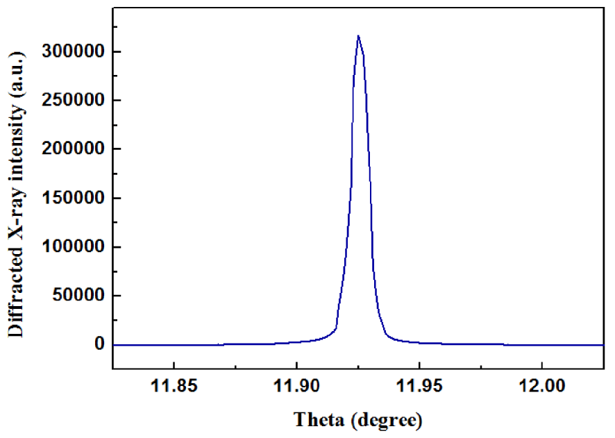
Figure 3. HRXRD pattern of the long-seed KDP crystal.
3.3 Transmittance of the long-seed KDP crystal
The transmission spectrum of a THG-oriented sample of the long-seed KDP crystal is shown in Figure 4. The vibration near 860 nm was caused by switching the detectors of the spectrometer at this wavelength. In the wavelength range of 377–1022 nm, the transmittance is higher than 90%, which is almost the same as that of the cuboid DKDP crystal. The transmittance at 355 nm is 82.9%, a little higher than that of the cuboid DKDP crystal[Reference Chen, Wang, Wang, Zheng, Zhang, Qi and Shao24]. The various factors responsible for the origin and influence of optical transmittance can be found from peer-reviewed literature[Reference Azhar, Anis, Rabbani, Shirsat, Baig, Hussaini, AlFaify and Khan34–Reference AlFaify, Shkir, Ganesh, Anis and Yahia36].
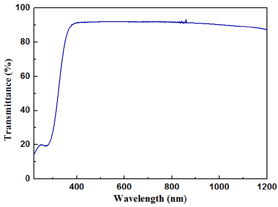
Figure 4. Transmittance of the long-seed KDP crystal.
3.4 Laser-induced damage property
The LID property at 355 nm of the THG-oriented sample cut from the long-seed KDP crystal is shown in Figure 5. The effective area of the laser spot is  $0.26~\text{mm}^{2}$. The fluence for the 50% probability of LID is
  $18.5~\text{J}/\text{cm}^{2}$ (3 ns, 355 nm), 38% higher than that of the cuboid DKDP crystal[Reference Chen, Wang, Wang, Zheng, Zhang, Qi and Shao24]. Several test points survive when the laser fluence exceeds
  $30~\text{J}/\text{cm}^{2}$ (3 ns, 355 nm), indicating the good LID property of the long-seed KDP crystal.
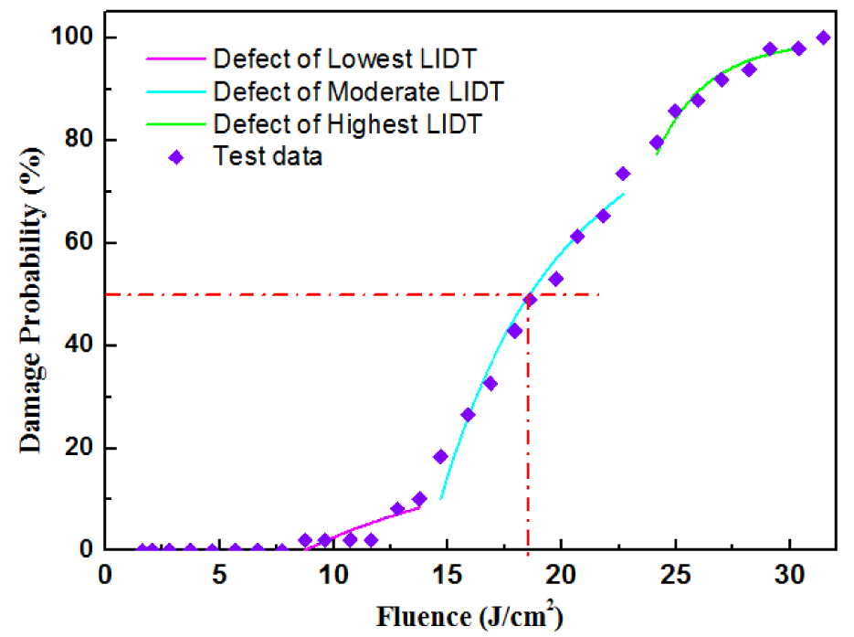
Figure 5. LIDT of the long-seed KDP crystal.
Table 1. Fitting of different kinds of defects.
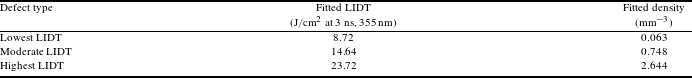
A model is used to quantify the LID property of the long-seed KDP crystal[Reference Natoli, Gallais, Akhouayri and Amra37, Reference Krol, Gallais, Grezes-Besset, Natoli and Commandre38]. In Figure 5, three types of defects are fitted. The fitted LIDT and density of different kinds of defects are shown in Table 1. The density is  $0.063~\text{mm}^{-3}$ for the defect that has the lowest LIDT, indicating that defects that can easily induce damage under 355 nm in the long-seed KDP crystal are rare. Some extrinsic factors such as incident photon energy, pulse width and polarization mode and intrinsic factors such as thermal expansion coefficient, electron avalanche breakdown and nonlinear absorption effects play decisive roles in laser damage properties of crystalline materials. Detailed explanations are given in Refs. [Reference Ramteke, Kalainathan, Anis, Muley, Baig and Algarni39–Reference Azhar, Hussaini, Shirsat, Rabbani, Shkir, Alfaify, Ghramh, Baig and Anis41].
3.5 Laser-induced damage morphology
Illuminated by a 532 nm probe laser, the LID scattering image of the THG-oriented sample is recorded by an online microscope system mounted on the laser damage facility. The microscope is placed orthogonally to the propagation direction of the 355 nm laser. Once the damage happens, the microscope immediately captures the LID scattering image. An LID scattering image at 30 J/cm2 (3 ns, 355 nm), is shown in Figure 6, with length about 10 mm, which is also the thickness of the sample. Even at such a high fluence, only three damage points appear within 10 mm, indicating that the long-seed KDP crystal has good damage resistance. Although it looks like six scattering points in the figure, there are actually only three LID points. Because of birefringence, the scattered light of each LID point is split into two beams (namely the o light and e light), forming two scattering points in the microscope.

Figure 6. LID scattering image at  $30~\text{J}/\text{cm}^{2}$ (3 ns, 355 nm).
The morphology of the damage points in Figure 6 is observed by an offline polarization microscope. The morphology of damage points in Figure 7 from left to right shows exactly the same points as in Figure 6. In Figure 7, all the damage points consist of a core, a distortion zone around the core and cracks extending from the core[Reference Hu, Zhao, Li and Xiao42, Reference Carr, Feit, Johnson and Rubenchik43]. Because the sample did not rotate when testing the morphology of the three points, all the cracks extend in only two directions, which should be the directions of the crystalline axes[Reference Burnham, Runkel, Feit, Rubenchik, Floyd, Land, Siekhaus and Hawley-Fedder44–Reference Yoshida, Jitsuno, Fujita, Nakatsuka, Yoshimura, Sasaki and Yoshida46]. An approach to evaluate damage performance provides statistics on damage pinpoint density, size and morphology as a function of fluence, wavelength and pulse duration and relates that to the resulting beam obscuration[Reference DeMange, Carr, Radousky and Demos47]. The power limitation was found to play a vital role in the use of rapidly grown KDP-type crystals in the ICF system.
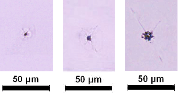
Figure 7. Morphology of the LID bulks in Figure 6.
4 Conclusions
Despite being the subject of study for more than 30 years, rapidly grown KDP-type crystals are still grown from a ‘point seed’. In this study, a long-seed KDP crystal with size  $471~\text{mm}\times 480~\text{mm}\times 400~\text{mm}$ was rapidly grown. With almost the same high cutting efficiency to obtain THG-oriented samples, this long-seed KDP-type crystal can grow from a seed that is shorter than that of the cuboid KDP-type crystal proposed in the recently published literature[Reference Chen, Wang, Wang, Zheng, Zhang, Qi and Shao24]. For example, to get 10 THG-oriented samples with size
  $460~\text{mm}\times 430~\text{mm}\times 10~\text{mm}$, the size of the seed should be at least 486 mm for the cuboid KDP-type crystal, while it is just 348 mm for the long-seed KDP-type crystal. Therefore, it is of practical significance since it is not always easy to get a long seed to grow a large cuboid KDP-type crystal. The long-seed KDP crystal also exhibits good crystalline quality since the FWHM of HRXRD is the same as that of the cuboid DKDP crystal[Reference Chen, Wang, Wang, Zheng, Zhang, Qi and Shao24]. As to the transmission and the LID performance, the long-seed KDP crystal is even better than the cuboid DKDP crystal[Reference Chen, Wang, Wang, Zheng, Zhang, Qi and Shao24]. Furthermore, new seeds with much longer size in the [001] crystallography direction than the original seed can be taken from the pyramidal portion down through the prismatic portion. In addition, because the carrier has a height greater than that of the long seed, there is no need to replace the carrier for a different seed with that of different height. For the cuboid KDP-type crystal, once the height of the carrier is set, the length of the seed must be equal to the height of the carrier. Therefore, the long-seed KDP-type crystal is more promising than the cuboid KDP-type crystal in engineering application.
Acknowledgement
This work was supported by the National Natural Science Foundation of China (No. 11535010).


 Open access