

Abstract
The streamer evolution of three-electrode pulsed surface dielectric barrier discharge (SDBD) in atmospheric air is studied with basic morphologic features, electrical characteristics and numerical simulation. Time resolved ICCD images demonstrate that besides the primary and secondary reverse streamers, a novel discharge mode-transitional streamer is also responsible for sustaining the streamer development in the three-electrode pulsed SDBD, which is different from the streamer mechanism in traditional two-electrode pulsed SDBD. Moreover, the discharge mode transition from the primary streamer to the transitional streamer is observed in a relative narrow discharge gap of 5 mm, while a relative large discharge gap of 19 mm results in a new phenomenon in which the primary streamer transits to the secondary reverse streamer without the process of transitional streamer. To determine the deposited energy of each streamer phase, an equivalent circuit model is built and it shows that the transitional streamer possesses the main energy. To make a further understanding of the formation and propagation of three streamer phases, a 2D fluid model is implemented and the streamer evolution and species distribution are analyzed. The results exhibit that the gathered positive ions in primary streamer head does not move forward when it is close to the second grounded (SG) electrode surface, because the same positive polarity of a cathode layer is formed on the SG electrode surface.
Export citation and abstract BibTeX RIS
1. Introduction
Non-thermal plasma has been considered as a promising technology for the wide field of applications including flow control [1–3], ozone generation [4, 5], plasma-assisted combustion [6, 7], medical therapy [8, 9] and pollutants treatment [10, 11]. As a common technique, surface dielectric barrier discharge (SDBD) can efficiently produce non-thermal plasma which generates a series of micro-discharges along the barrier dielectric surface. Generally, a supplying of pulsed voltage with a fast rise and decay time promotes the rapid ionization of air, which is beneficial for the generation of plasma. In fact, the effective applications of plasma in combustion, waste treatment, etc require more electrical energy to be injected into the discharge reactor. As a result, the optimization of reactor structure and pulse parameter has been carried out to improve the performance of SDBD [12–15]. Furthermore, it is demonstrated that a three-electrode configuration coupled positive pulsed voltage with negative DC voltage can enhance the discharge plasma intensity, but two power supplies are required to realize the three-electrode electric discharge [16, 17]. In this paper, a similar three-electrode configuration in which the negative DC electrode is replaced by a grounded electrode is put forward to reduce the complexity of the experimental system, and the streamer evolution is studied due to its importance for the generation of plasma.
Generally, the key problem of physical characteristics for SDBD is the generation and propagation of streamers caused by electrons which can acquire energy from the electric field and result in a number of species generation and energy release [18, 19]. It has been reported that various properties of different streamer phases play a significant role in discharge plasma. In a pulsed pin-to-plane air discharge, after the primary streamer bridges the anode and cathode, the secondary streamer appears in the anode region due to the applied pulsed voltage and produces most of excited species [20, 21]. Using the same needle-plane electrode configuration filled with synthetic ester liquid, two streamer phases are also observed, where a secondary reverse streamer is formed by the reverse electric field during the falling edge of pulsed voltage [22]. However, the physical mechanism of the secondary reverse streamer is different to that of secondary streamer in bulk gas because the residual charges accumulated at the gas/liquid interface can induce a reverse electric field which produces the secondary back discharge. For the pulsed SDBD, the charges left by the primary streamer are trapped on the barrier dielectric surface, which can further result in the reverse electric field. Therefore, two streamer phases with different morphologies developing on the rising edge and on the decreasing phase of the pulsed voltage are also observed in traditional two-electrode pulsed SDBD [23, 24]. Moreover, due to the apparent electrode configuration difference to the traditional two-electrode pulsed SDBD, the mechanism of streamer evolution may be different in three-electrode pulsed SDBD. Therefore, a further insight into streamer behaviors of three-electrode pulsed SDBD can contribute to its applications.
Numerical simulation has been utilized as an effective method to reveal some puzzles of the underlying mechanism in different streamer phases, especially for the generation and distribution of active species. For example, Ono employed fluid model and demonstrated that most reactive species are generated from the secondary streamer phase in pulsed point-to-plane streamer discharge, and the primary streamer has a higher reduced electrical field than that of the secondary streamer [25]. Using a 2D fluid model, Kushner [26, 27] and Wang [28] contributed to a further understanding of the reactive species production from the surface discharge and the volume discharge in packed bed reactor, which is not easy to diagnose directly through experiments. Additionally, the electric field enhancement in the catalyst pores has been confirmed by a two-dimensional fluid model [29, 30]. In a pin-to-pin electrode, the detailed formation and propagation of the two streamers (positive streamer and negative streamer), and the distribution of electron density are obtained through numerical simulations [31, 32]. For the traditional two-electrode pulsed SDBD, two streamer phases are studied through a 2D fluid model, and they demonstrated that the phenomenon of secondary reverse streamer is produced by residual accumulated charge [33, 34]. However, the fundamental understanding of three-electrode pulsed SDBD via numerical simulation is relatively rare.
In the present study, the streamer evolution in three-electrode pulsed SDBD under atmospheric air is investigated through an ICCD camera. And the deposited energies of different streamer phases are calculated according to an equivalent circuit model. Moreover, a numerical model of the three-electrode pulsed SDBD is implemented and analyzed in order to gain a further insight into the fundamental physics for the behaviors of three streamer phases.
2. Experimental set-up and methodology
2.1. Electrical and optical diagnostics
A schematic of the experimental set-up and a detailed three-electrode pulsed SDBD configuration in this work are presented in figures 1(a)–(c), respectively. A high-voltage (HV) pulse generator (HVP-20P, Xi'an Smart Maple Electronic Technology Co. Ltd, China) with a rise time of 50 ns, a decrease time of 50 ns and a varying pulsed voltage amplitude is applied to the HV electrode for the generation of plasma in discharge gap. Pulsed voltage and current are measured by a HV probe (Tektronix P6015A) and a current probe (Tektronix P6021A), respectively. The electric currents (total current  first current
  and second current
  ) through the three positions of grounded electrode are measured separately, which are indicated in the figure 1(a). The waveforms of applied voltage and current are recorded on a digital oscilloscope (Tektronix DPO3012). To measure the spatial-temporal evolution of discharge streamer along the barrier dielectric surface, discharge images are taken by an ICCD camera (Princeton, PI-MAX 3 1024i equipped with a Canon 50 mm F/1.8 UV lens). A varying gate width of the ICCD camera is adopted to investigate the streamer propagation and three streamer phases. The duration time of three streamer phases are determined by the streamer propagation time with a gate width of 5 ns. Furthermore, the ICCD camera is synchronized with the HV pulse via a signal exported from the pulse power.

Figure 1. Experimental system (a) schematic of the experimental set-up, (b) front view of the three-electrode configuration, (c) top view of the three-electrode configuration.
Download figure:
Standard image High-resolution imageThe three-electrode pulsed SDBD configuration which consists of HV electrode, the first grounded (FG) electrode, the second grounded (SG) electrode and barrier dielectric, is shown in the front view and top view of figures 1(b) and (c). The barrier dielectric is made of Teflon flat plate with the thickness of 1 mm. HV electrode and SG electrode are made of aluminum foils with 70 mm in length, 10 mm in width and 0.1 mm in thickness. Additionally, the HV electrode and SG electrode are arranged on the same side of barrier dielectric surface with varying discharge gaps of 5, 13 and 19 mm. The FG electrode consists of an aluminum foil with a length of 70 mm and a thickness of 0.1 mm. Additionally, the width of FG electrode is consistent with the size of discharge gap between the HV electrode and the SG electrode.
2.2. Equivalent circuit model for three-electrode pulsed SDBD
The voltage drop and discharge current of plasma channel are critically important for describing pulsed SDBD, especially the energy deposition for different streamer phases. But it is very difficult to be measured directly in experiments. Typically, the total steady energy can be calculated by integrating the measured applied voltage and total current [35]. Unfortunately, this method can not effectively distinguish the deposited energy of different streamer phases. Therefore, a theoretical model of the pulsed discharge process is significant for getting the voltage drop, discharge current and deposited energy of different streamer phases. The equivalent circuit model of traditional pulsed DBD is simplified as the circuit which consists of impedance and capacitance [36, 37]. Based on the similar method, an equivalent circuit model of the three-electrode pulsed SDBD is developed, as shown in figure 2. Where  is the capacitance between the HV electrode and the FG electrode.
  represents the capacitance between the HV electrode and the upper surface of barrier dielectric.
  is the capacitance between the HV electrode and the SG electrode.
  is the capacitance between the upper surface of barrier dielectric and the FG electrode.
  denotes the impedance of the plasma channel between the HV electrode and the upper surface of barrier dielectric.
  is the impedance of the plasma channel between the HV electrode and the SG electrode. The capacitances of
  can be ignored especially during the streamer propagation process. Then the equivalent circuit model can be simplified as figure 2(c). Where
  varies with the different length and area of streamers. And
  and
and  are constants which are fixed in 1.5 pF and 0.25 pF in our experiments, respectively.
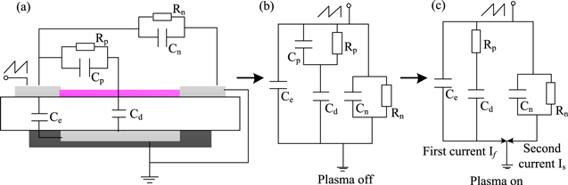
Figure 2. Equivalent circuit model for three-electrode configuration.
Download figure:
Standard image High-resolution imageAccording to the equivalent circuit model, when the plasma is ignited, the electric current including displacement current is measured by a current probe (see figure 1). As a result, the first discharge current  the second discharge current
  and the total discharge current
  can be calculated by the following equation (1).
where t is the time. U is the applied pulsed voltage measured by a HV probe. Furthermore, the deposited energies on the equivalent impedance of  and
and  and total deposited energy of the three-electrode pulsed SDBD can be calculated by the following formulas (2)
Here,  and
and  represent the voltage drop for the impedance of
  and
and  respectively.
3. Results and discussion
3.1. Streamer propagation in pulsed SDBD
The images for the formation and propagation of streamers in the three-electrode single pulsed SDBD are taken by an ICCD camera with the gate width of 5 ns, as displayed in figure 3. In order to ensure that no electrical charges are accumulated on the barrier dielectric surface before every single pulse discharge, a wet paper is utilized to wipe the surface of reactor after one pulse discharge. Then a rubber pipette bulb is utilized to dry the surface of discharge reactor configuration. It can be noted that there are three streamer phases involving the primary, transitional and secondary reverse streamers, which is much different to the traditional two-electrode pulsed SDBD which includes the primary and secondary reverse streamers (see figure 4). For the three-electrode pulsed SDBD, the primary streamer characterized with a streamer-like morphology is ignited from the edge of HV electrode at the time of 15 ns, and then propagates along the barrier dielectric surface. Finally, it reaches the SG electrode at the time of 40 ns with the average streamer propagation velocity of 0.52 mm ns−1. When the primary streamer gets close to the SG electrode, the luminous intensity of primary streamer head becomes brighter. After the primary steamer arrives at the SG electrode, a novel discharge phase appears in the discharge gap which is produced at the ionized channel left by the primary streamer, and it does not indicate the obvious propagation direction. We define this novel discharge phase of a duration time from 40 to 140 ns as transitional streamer, which is produced due to the applied pulsed voltage and accumulated charges on barrier dielectric surface. With the transitional streamer disappearing, the secondary reverse streamer characterized with a diffuse morphology is produced and develops along the barrier dielectric surface. The length of secondary reverse streamer is shorter than that of primary streamer, because the accumulated charges are not enough to induce a long streamer. The detailed mechanisms of the enhanced primary streamer head luminous intensity, the generation of transitional streamer and the formation of secondary reverse streamer will be analyzed in sections 3.2 and 3.5. Additionally, it can be seen that the luminous intensity of secondary reverse streamer increases firstly and then decreases with the time, due to the consumption of accumulated charges. Moreover, it also can be noted that the optical emission intensity of primary streamer in the three-electrode pulsed SDBD is higher than that in the traditional two-electrode pulsed SDBD (detailed structural parameters of reactor can be found in our previous work [34]) due to the larger electric field induced by the SG grounded. But the luminous intensity of secondary reverse streamer is weak in the three-electrode pulsed SDBD, because a number of surface charges are consumed during the transitional streamer phase.
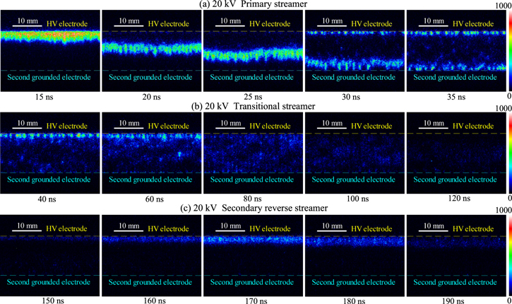
Figure 3. Spatial-temporal evolution of streamer propagation in three-electrode pulsed SDBD under 13 mm discharge gap and 20 kV. (a) Primary streamer, (b) transitional streamer, (c) secondary reverse streamer.
Download figure:
Standard image High-resolution image
Figure 4. Spatial-temporal evolution of streamer propagation in traditional two-electrode pulsed SDBD at 20 kV. (a) Primary streamer and (b) secondary reverse streamer.
Download figure:
Standard image High-resolution imageFigure 5 shows the electrical characteristics and average streamer luminous intensity of the traditional two-electrode pulsed SDBD and the three-electrode pulsed SDBD under 20 kV. It can be noted that the three-electrode pulsed SDBD enhances the discharge intensity, which can be reflected by the deposited energy and streamer optical emission intensity. The deposited energy of three-electrode pulsed SDBD is 3.52 mJ, which is about 2.21 times that of traditional pulsed SDBD (1.59 mJ). Furthermore, the positive current in three-electrode pulsed SDBD is larger than that in traditional pulsed SDBD, but the negative current is smaller. The average luminous intensity of secondary reverse streamer in three-electrode pulsed SDBD and traditional two-electrode pulsed SDBD also can confirm this phenomenon.

Figure 5. Comparison of traditional two-electrode pulsed SDBD and three-electrode pulsed SDBD under 20 kV for (a) electrical characteristics and (b) average streamer luminous intensity. (Dotted line is traditional two-electrode pulsed SDBD and solid line is three-electrode pulsed SDBD.)
Download figure:
Standard image High-resolution image3.2. Characteristics of three streamer phases
Figure 6 shows the streamer luminous phases in three-electrode single pulsed SDBD under different pulsed voltages. The single pulse discharge consists of the primary, transitional and secondary reverse streamers. The primary streamer shows obvious filament morphology and bridges the HV electrode and SG electrode. The transitional streamer emerges in the ionized channel which is left by the primary streamer, due to the roles of applied voltage and accumulated charges. When the primary streamer passes through the barrier dielectric surface, the passing region which accumulated charges can be regarded as a 'high-voltage point' [38, 39]. Meanwhile, the region which is not ionized by the primary streamer is set as a 'low-voltage point'. Thus, a streamer discharge can be generated from the 'high-voltage point' to the 'low-voltage point', which causes a more diffuse morphology for the transitional streamer than that of primary streamer. This similar phenomenon is also observed in charged barrier dielectric surface [40]. For the secondary reverse streamer, the applied pulsed voltage is lower than the electric potential formed by the charges accumulated on the barrier dielectric surface. Therefore the secondary reverse streamer is a negative streamer with a diffuse morphology and is also ignited from the edge of HV electrode. With the increase of pulsed voltage, the optical emission intensities of the primary, transitional and secondary reverse streamers increase.
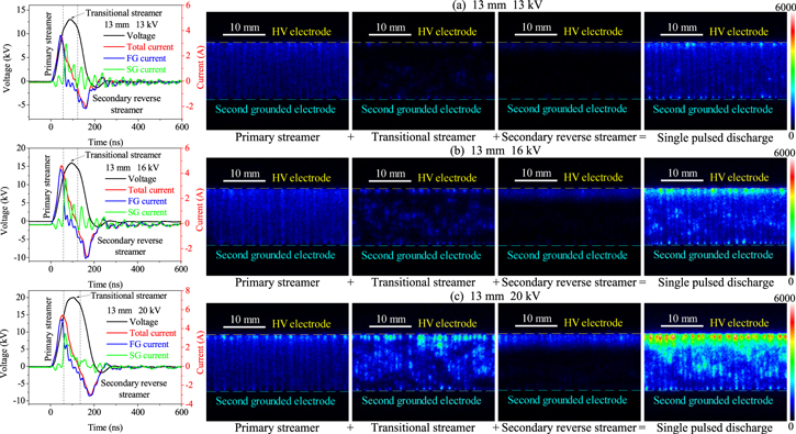
Figure 6. Primary streamer, transitional streamer and secondary reverse streamer in 13 mm discharge gap with the pulsed voltage of (a) 13 kV, (b) 16 kV, (c) 20 kV.
Download figure:
Standard image High-resolution imageThe three streamer phases marked in time evolution of the voltage and current are separated by the streamer images, as shown in the left images of figure 6. The primary streamer exists in the initial rising regime of pulsed voltage. The transitional streamer exists around the maximum pulse peak voltage regime from the later rising to the initializing decaying of pulsed voltage. For the secondary reverse streamer, it exists in the later decaying regime of pulsed voltage. Additionally, the measured FG current, SG current and total current increase with the increasing applied pulsed voltage. One can remark that positive current peak of total current and FG current mainly represents the intensity of primary streamer. Besides, the negative current peak of total current and FG current mainly indicates the intensity of secondary reverse streamer. The SG current reflects the excess positive ionized species produced by the primary, transitional and secondary reverse streamers [16]. Furthermore, a high SG current demonstrates that the discharge intensity is enhanced.
3.3. Evolution of streamer luminous phase
To have a further insight into the streamer behaviors, the evolutions of three streamer phases in different discharge gaps (5 mm and 19 mm) at 13 kV are presented in figure 7. It can be noted that the different discharge mode transition appears in the varying discharge gaps. When the discharge gap is set at a relative small value of 5 mm, a strong transitional streamer is produced because of the high electric field [41]. But the secondary reverse streamer becomes too weak to be captured due to the fact that the accumulated charges are consumed during the transitional streamer phase. However, at a relative large discharge gap of 19 mm, the transitional streamer becomes too weak to be captured due to the low electric field. At this time, the secondary reverse streamer appears, because fewer charges are consumed during the transitional streamer phase.
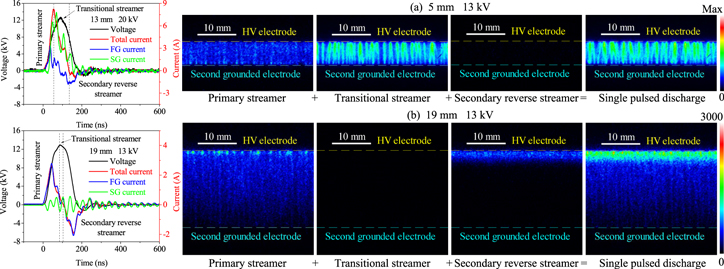
Figure 7. Evolution of streamer luminous phase under 13 kV with the discharge gap of (a) 5 mm (Noted that the Max for the transitional streamer and single pulsed discharge is 20 000, the else is 3000.) and (b) 19 mm.
Download figure:
Standard image High-resolution imageIt also can be noted that the discharge intensity varies with the different discharge gaps. A strong streamer luminous intensity of single pulsed discharge is obtained in a relative narrow discharge gap because the SG electrode can enhance the discharge intensity via a coupled electric field from the HV electrode, FG electrode and SG electrode. This phenomenon also can be reflected from the high positive current peak in a narrow discharge gap. However, the negative current peak is high in a relative large discharge gap because the secondary reverse streamer is enhanced via more accumulated positive ions. The decrease in measured SG current with larger discharge gap reveals that more positive charges are accumulated on the barrier dielectric surface, implying that less positive ionized species reaches the SG electrode.
3.4. Deposited energy in three streamer phases
Based on the detailed method introduced in section 2.2, the electrical characteristics of three-electrode configuration with a 13 mm discharge gap are performed. The measured pulsed voltage, total current, FG current and SG current are presented in figure 6. According to formulas (2), the deposited energy curves are plotted in figure 8 with solid lines. The dotted lines are obtained via the general method [35] which is based on the integration of the applied pulsed voltage and current crossing the FG electrode, SG electrode and total grounded electrode. It can be expressed as 
 and
and  These results show the deposited energy crossing the FG electrode, SG electrode and total grounded are consistent, which demonstrates the reliability of the equivalent circuit model. Comparing the deposited energy of each streamer phase obtained according to the duration time of the three streamer phases from the ICCD images, it is found that the energies of the primary, transitional and secondary reverse streamers are 0.64 mJ, 1.04 mJ and 0.46 mJ under 16 kV, respectively. It can be noted that the transitional streamer possesses almost one half of the single pulsed discharge energy.
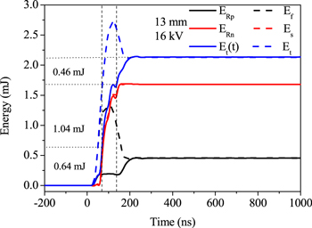
Figure 8. Deposited energy in 13 mm discharge gap at the pulsed voltage of 16 kV.
Download figure:
Standard image High-resolution imageBased on the charge transfer formula ( ), the electrical charges crossing the FG electrode and SG electrode are obtained, as displayed in figure 9. The electrical charge Q1 on FG electrode reflects the charge evolution on barrier dielectric surface. Besides, the electrical charge Q2 on SG electrode reflects the excess of positive ionized species emitted from the primary, transitional and secondary reverse streamers because the SG electrode is regarded as the cathode during the whole pulsed discharge process. Figure 9 shows that the electrical charges accumulated on barrier dielectric surface increase firstly and then decrease to the same value because the positive ions are generated and accumulated on the surface during the primary streamer phase, and then are consumed by the electron and negative ions during the transitional and secondary reverse streamers phases. For the electrical charge evolution in SG electrode, it lags behind the FG electrode because the positive ionized species need time to propagate from the HV electrode towards the SG electrode [16].

Figure 9. Charge evolution in 13 mm discharge gap from the FG electrode and SG electrode.
Download figure:
Standard image High-resolution image3.5. Numerical simulation of streamer propagation
To make a further understanding on the underlying mechanism of streamer behaviors in three-electrode pulsed SDBD, a 2D fluid model coupled with the continuity equation of particles, the electron energy conservation equation and the Poisson's equation is undertaken with the built-in plasma module of COMSOL Multiphysics.


here,  and
and  are the density of each species and electron energy density, respectively.
  is the time.
  and
and  represent the charged particles mobility and electron energy mobility, respectively.
  denotes the electric field vector.
  and
and  indicate the diffusivity coefficient of heavy species and electron energy, respectively.
  and
and  are the chemical source of species and electron energy, respectively.
  and
and  denote the vacuum dielectric constant and relative permittivity of the material, respectively.
  represents the space charge density.
The initial electron density is set to 1 × 10¹⁵ m−3. Different initial electron densities are employed in the model and the results show that the high electron density can reduce the calculation time without apparent effect on the streamer distribution [42]. Gas pressure is set to atmospheric pressure and the temperature is set to 293.15 K. Both of them are similar to that of experimental conditions. HV electrode is implemented with the pulsed voltage. The boundaries of FG electrode and SG electrode are set to grounded with the expression of  Due to the fact that the residual charges can be accumulated on barrier dielectric surface, the surface of barrier dielectric is set as surface charge accumulation, which can be expressed as
  Where
Where  is the surface charge density.
  and
and  represent the normal components of the total ion current density and the total electron current density, respectively. Charge conversation is set for the barrier dielectric. The boundaries of the left, top and right in gas domain are set of insulation. Moreover, the boundaries for the surface of HV electrode, barrier dielectric and SG electrode are set of wall. Considering that the heavy species can impact the wall and then induce the emission of secondary electron, the secondary processes on the surface of barrier dielectric and electrode are carried out in the numerical model. The corresponding expression is
  and
and  Where
Where  and
and  is the electron thermal velocity and electron density, respectively.
  is the secondary electron emission coefficient from species
  Surface reactions of excited species and ions impact the surface of electrode and barrier dielectric, and then turn into ground state species. As a result, the secondary electron with a probability of 0.01 and energy of 2.5 eV is emitted from the surface. Moreover, to make the calculation manageable and reliable, 61 chemical reactions and 25 species are included in the chemical reaction model.
Unstructured triangle mesh is employed to discretize the computational domain, as shown in figure 10. Considering the high gradient of species density and reduced electric field, a minimum cell size of 10 μm [32] is implemented for the wall of electrode and barrier dielectric. In addition, a coarse mesh is adopted in the other domain to reduce the computational resource. As a result, 47 225 nodes are obtained in the configuration. The time dependent solver and the time step of backward differentiation formula method are implemented in the numerical model. A relative tolerance of 0.01 is set in the case. The direct linear system solver of parallel sparse direct solver (PARDISO) is used to obtain the result. Further detailed explanation of the numerical model can refer to our previous paper [34].

Figure 10. Computational domain.
Download figure:
Standard image High-resolution imageFigure 11 shows the evolution of the primary, transitional and secondary reverse streamers (electron density, reduced electric field and electron impact ionization source) in the three-electrode pulsed SDBD. The numerical simulation results match the experimental observations and qualitatively reflect the experimental trend in streamer morphology and discharge current, which confirms the validity of the model. From figure 11, we can see that the primary streamer is ignited from the edge of HV electrode and propagates above the barrier dielectric surface with several micrometers due to the cathode layer [33]. When the primary streamer propagates close to the SG electrode, a high reduced electric field can be induced in the SG electrode surface, as shown in figure 11(b). The reason is that the primary streamer head is gathering a number of positive ions, which can be considered as an anode, leading to a great electric field between the primary streamer head and the SG electrode. This phenomenon is also observed in the experiment, where a brighter luminous streamer appears when it is close to the SG electrode. In addition, the streamer seems to be far away from the barrier dielectric surface, which can be attributed to the drift of electron resulted by the presence of the vertical component of electric field. However, the reduced electric field and electron impact ionization source are too weak to induce an obvious luminous phenomenon, resulting that there is no visual plasma channel observed far away from the surface of barrier dielectric (more than 1 mm) during the experiment.
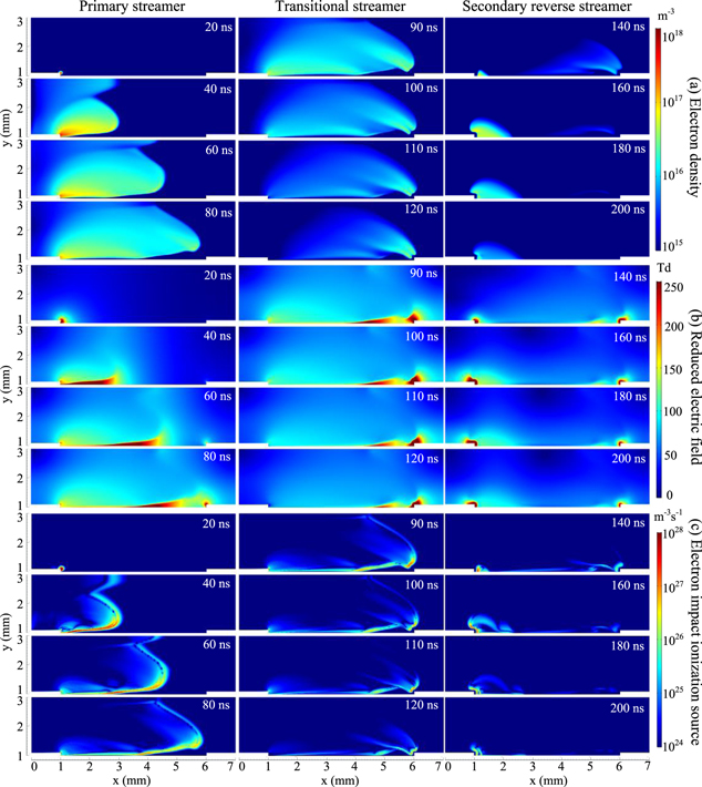
Figure 11. Streamer propagation in 5 mm discharge gap at 13 kV (a) electron density, (b) reduced electric field and (c) electron impact ionization source.
Download figure:
Standard image High-resolution imageDuring the transitional streamer phase, a number of positive charges accumulate on the surface of barrier dielectric and SG electrode (cathode layer), resulting in the production of electrons (high impact ionization source, see figure 11(c)) [33], and then the born electrons can be drifted to the HV electrode under the effect of electric field. The presence of cathode layer formed on SG electrode surface keeps the transitional streamer several micrometers away from the SG electrode. It also can be noted that the gathered positive ions in the primary streamer head does not move forward during the transitional streamer phase because the gathered positive ions in the primary streamer head and cathode layer formed on the SG surface show the same polarity. The remaining of primary streamer head causes the transitional streamer to propagate above the barrier dielectric surface with a relative large gap in the vicinity of the SG electrode.
At the falling edge of pulsed voltage, the secondary reverse streamer is generated from the HV electrode because the electric potential formed by the accumulated charges on barrier dielectric surface is larger than the applied pulsed voltage, which will induce a reverse electric field. However, the secondary reverse streamer is not observed obviously in the experiment, because the optical emission intensity of secondary reverse streamer is too weak to be captured. At this time, the cathode layer is also formed on the surface of HV electrode, leading to the secondary reverse streamer away from the HV electrode with tens micrometer.
The calculated total current and the current through the SG electrode are presented in figures 12(a) and (b), respectively. For the total current, the positive part of total current mainly consists of electron current, and the negative part is corresponding to the ion current. This is because that the electrons are generated from the cathode layer and drifted to the HV electrode during the primary streamer and transitional streamer phases. The reason for the negative part of total current is that electrons are generated from the cathode layer formed on the HV electrode surface, and then drifts to the barrier dielectric surface under the effect of the electric field. At this time, the positive ions are generated in the cathode layer and gets through the HV electrode. For the SG electrode current, the current getting through the SG electrode mainly consists of ion current, while the electron current is almost zero. This is because the cathode layer is formed on the SG electrode surface, resulting in a number of ionization reactions in this region. The generated electrons drift to the HV electrode and the generated ions flow through the SG electrode.
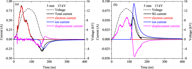
Figure 12. Calculated current for (a) total current and (b) SG electrode current.
Download figure:
Standard image High-resolution image3.6. Spatial-temporal distribution of charged species, oxygen atom and surface charge
Due to the fact that the charge has a significant effect on the formation and propagation of streamer, the species density and species source term of positive ions, negative ions and oxygen atom during the transitional streamer (100 ns) are displayed in figure 13. The positive ions with high density are generated in the cathode layer because the high reduced electric field in this region results in the ionization reactions. For the negative ions and oxygen atoms, both of them distribute above the barrier dielectric surface, which is similar to the distribution of electron, because they are mainly produced through the electrons drifted from the SG electrode to HV electrode under the effect of electric field.
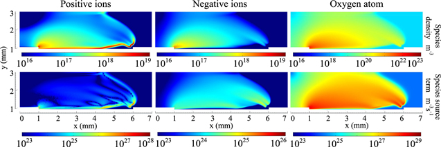
Figure 13. Spatial-temporal variations of positive ions, negative ions and oxygen atom during the transitional streamer (100 ns) in 5 mm discharge gap at 13 kV.
Download figure:
Standard image High-resolution imageBased on the numerical simulation, the temporal evolution of surface charge density on the barrier dielectric surface is shown in figure 14. The surface charge density increases with the development of primary streamer ranging from the time of 20 to 80 ns, then it decreases due to the transitional and secondary reverse streamers. After the discharge process, the maximum surface charge density appears in the middle of barrier dielectric surface. There is also a small peak value of surface charge near the SG electrode after the primary streamer arrives at the SG electrode. This is because a number of positive charges gather on the surface of SG electrode, which shows a same polarity with the primary streamer head.

Figure 14. Temporal distribution of surface charge density in 5 mm discharge gap at 13 kV.
Download figure:
Standard image High-resolution image
4. Conclusions
In this work, the streamer behaviors of three-electrode pulsed SDBD are experimentally and computationally studied. The main results are as follows:
- 1.Compared to the traditional two-electrode pulsed SDBD, the three-electrode pulsed SDBD induces stronger discharge in terms of electrical characteristics and average streamer luminous intensity. Besides the primary and secondary reverse streamer, a novel streamer phase (transitional streamer) characterized with a relative diffuse morphology and random propagation, is formed in the ionized channel after the primary streamer reaches the SG electrode. Based on the equivalent circuit model, the deposited energies of three streamer phases show that the transitional streamer possesses almost one half of electrical energy in a 13 mm discharge gap at 16 kV.
- 2.Under a relative narrow discharge gap of 5 mm, a transition from the primary streamer to the transitional streamer occurs in single pulsed discharge. An enlargement in the discharge gap will decrease the intensity of single pulsed discharge, especially for the transitional streamer. As a result, only the primary and secondary reverse streamers develop in a relative large discharge gap of 19 mm. Furthermore, the luminous intensity of secondary reverse streamer increases in a large discharge gap, because fewer charges are consumed during the transitional streamer phase.
- 3.The primary streamer propagates above the barrier dielectric surface and the secondary reverse streamer is formed away from the HV electrode surface with several micrometers due to the effect of cathode layer. During the transitional streamer phase, a cathode layer is formed on the surface of the SG electrode and barrier dielectric, resulting in the local enhancement of reduced electric field and the production of electrons, and then the generated electrons are drifted to the HV electrode under the effect of electric field.
- 4.When the primary streamer head is close to the SG electrode, a high reduced electrical field is induced on the SG electrode surface. Because the primary streamer head gathers a number of positive ionized species, which can be regarded as anode compared to the SG electrode. During the transitional streamer phase, the gathered positive ions in the primary streamer head does not move forward because the cathode layer with lots of positive ions forms on the SG electrode surface. This phenomenon causes the transitional streamer to propagate above the barrier dielectric surface with a relative large gap in the vicinity of the SG electrode.
Acknowledgments
This work was supported by the National Natural Science Foundation of China (Grant Nos. 51877027, 51477025, 21577011, 51977024).