

Abstract
Atmospheric pressure cold plasma technology has great application potential in the field of food safety. A novel atmospheric air dielectric barrier discharge device has been designed to generate plasma directly on the surface of spherical fruit. This device consists of the quartz tube, the high-voltage electrode attached to the outer wall of the quartz tube, and the fruit placed onto the inner surface of the quartz tube, acting as the ground electrode. The intensified charge-coupled detector images show that a uniformly scanning discharge channel is formed between the surface of treated substance and the inner wall of quartz tube. When the treated substance is rolled in the device, the uniform plasma is directly formed over the fruit surface. The bactericidal efficiency of plasma against pathogenic microorganisms on rolling fruit surface has been studied. The number of Staphylococcus aureus (S. aureus) on the surface of fruit treated by plasma for 15 s in rolling state is 1.57 log10 CFU less than that of the static state. Compared with the initial bacterial concentration, the number of S. aureus on the surface of 1 cm2 decreases by 5.9 log10 CFU after plasma treatment of rolling fruit for 15 s. In conclusion, the fruit surface is uniformly treated by the novel plasma device and S. aureus on the fruit surface was sterilized without causing thermal damage to the fruit surface.
Export citation and abstract BibTeX RIS
1. Introduction
Fruit is an indispensable part of human diet, with high vitamins and dietary fiber that helps digestion. However, fruit is also a carrier of foodborne pathogens, the proliferation of which may seriously threaten human health and the quality of the fruits. Food-borne pathogens may cause a variety of diseases, including diarrhea, nausea and other acute gastrointestinal diseases [1–3]. It therefore poses an urgent need to find a green technique to disinfect foodborne pathogens on the surface of fruits to ensure the food safety.
Atmospheric pressure cold plasma (ACP) has been widely used in agriculture [4, 5], sewage purification [6, 7], plasma medicine [8–10], etc [11, 12] due to its advantages of environmental-friendly and high sterilization efficiency. Food treatment with ACP can be classified in direct and indirect mode. The direct treatment implies immersing the food in the plasma region, and the indirect treatment implies that the foods are placed outside the plasma region. The indirect treatment of fruits by ACP has been widely reported, such as the use of activated gases produced by plasma [13, 14] or plasma activated liquids to treat foods [15–17]. Ziuzina et al [18] used ACP-generated plasma-activated gas to sterilize Escherichia coli (E.coli), Salmonella enterica Typhimurium (S. Typhimurium) and Listeria monocytogenes (LMO) on the surface of tomato and strawberry. Beyhan Gunaydin Dasan et al [19] studied the effect of plasma-activated gas generated by gliding arc discharge on the decontamination of stainless steel (SS), silicon (Si) and polyethylene terephthalate (PET) surfaces. When nitrogen was used as working gas for 5 min, the reduction of E. coli and Staphylococcus epidermidis on the surface of SS, Si and PET was 2.72 ± 0.82, 4.43 ± 0.14 and 3.18 ± 0.96 log10 CFU ml−1, 3.76 ± 0.28, 3.19 ± 0.31, and 2.95 ± 0.94 log10 CFU ml−1, respectively. Jayasena et al [20] found that after 10 min treatment with plasma-activated gas, LMO, E. coli and Salmonella decreased 2.04, 2.54, and 2.68 log10 CFU g−1 on the surface of pork butt sample, as well as 1.90, 2.57, and 2.58 log10 CFU g−1 on beef loin samples. Our previous studies showed that 1.8 log10 CFU g−1 S. aureus on the surface of fresh-cut kiwifruit was sterilized by plasma-activated water (PAW) treatment and the antioxidant capacity of fresh-cut kiwifruit was improved after PAW treatment [15]. The above studies suggest that the indirect treatment is an effective method for ACP to inhibit the number of microorganisms on fruit surface. However, indirect treatment still has several shortcomings such as low energy efficiency and sterilization time in minute scale. At present, the use of plasma jet and surface dielectric barrier discharge (DBD) is the main method of plasma direct treatment of fruit [21, 22]. Considering the practical application, the surface of fruit presents complex 3D structure, plasma jet and surface DBD are difficult to generate uniform plasma on the fruit surface. The plate-to-plate DBD with a large electrode gap is difficult to achieve at atmospheric pressure. Therefore, a new ACP device is urgently needed to solve the dilemma of ACP application in food field.
In this study, a novel atmospheric air DBD device is designed to generate plasma directly on the surface of the rolling fruit. The development of discharge is captured by a synchronized intensified charge-coupled detector (ICCD) camera. The applied Laplacian electric field distribution of the device is studied and the mechanism of the discharge development in rising slope and falling slope of the applied voltage are analyzed. Moreover, the sterilizing efficiency of plasma on pathogenic microorganisms on the surface of rolling fruit and the effect of plasma treatment on fruit surface temperature is studied.
2. Method and materials
2.1. Experimental setup
The schematic diagram of the plasma device and the corresponding experimental setup are shown in figure 1. The plasma device consisted of a copper mesh as H.V. electrode, a quartz tube (inner diameter: 4.6 cm, outer diameter: 5 cm, 40 cm, length: 40 cm) as dielectric barrier and a grounded copper foil (length: 40 cm, width: 1.0 cm). The fruit is placed on copper foil as a ground electrode. As shown in figure 1(a), the copper mesh is tightly attached to the outer wall of the quartz tube, and connected to DC nanosecond pulsed H.V. power supply. The copper mesh is 38.0 cm in length, 1.0 cm away from each end of the quartz tube, and its width is 12.4 cm, covering 85% of the outer circumference of the tube. Two electrical tapes with 1.0 cm width are affixed to both ends of the quartz tube to avoid redundant discharges. Inside the quartz tube, the copper foil is tightly attached to the inner wall.

Figure 1. The schematic diagram of (a) plasma device and (b) experimental setup.
Download figure:
Standard image High-resolution imageThe plasma device is driven by the DC nanosecond pulsed H.V. power supply (Xi'an Smart Maple Electronic Technology Co., Ltd HVP-20P). In this study, the values of applied voltage, frequency, and pulse width of the voltage are kept constant at 17 kV, 1 kHz, and 3 µs, respectively. The rising and falling slopes of the positive square wave H.V. pulse have a voltage slope of approximately 340 V ns−1. The development of plasma is captured by an ICCD camera (Andor iStar DH712). The detailed trigger method of the H.V. power supply and the camera has been described in our previous study [23]. The applied voltage and the discharge current are measured by an H.V. probe (Tektronix P6015A) and a current monitor (Pearson 4100), respectively. The waveforms are recorded by an oscilloscope (Tektronix MDO3104). In order to better study the development of plasma on the surface of the sphere and ensure the repeatability of discharge, the same size steel ball is used instead of the apricot for the diagnosis and analysis of the plasma development.
In order to better understand the development of plasma, the finite element method is used to calculate the distribution of applied Laplacian electric field distribution. The above calculations are implemented using COMSOL version 5.3 software [24], and the detail method has been described in our previous study [25]. The structure parameters of the model were consistent with those in the experimental configuration.
2.2. Sample preparation
Staphylococcal food poisoning is the most common bacterial food poisoning, which may lead to sudden severe nausea and vomiting, abdominal cramps, diarrhea and fever [26]. 20 µl of S. aureus solution with the concentration of 109 CFU ml−1 is inoculated on aseptic gauze with an area of 1 cm2. The distribution of the gauze pieces on the apricot surface is shown in figure 2. The five specific locations, named A, B, C, D and E from right to left (front view) are evenly distributed on the upper half of the fruit. The concentration of S. aureus inoculated on the gauze is calculated by following equation:

where C1 and C2 are the concentration of S. aureus inoculated on the gauze and the concentration of S. aureus solution, V represents the volume of inoculated S. aureus solution. In this study, the value of C1 was 2 × 10⁷ CFU cm−2.
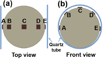
Figure 2. The distribution of the gauze pieces on the apricot surface (a) from top view; (b) from front view.
Download figure:
Standard image High-resolution imageApricots with good surface and no mechanical damage were purchased in Dalian local mall for microbial purification experiment. Five pieces of inoculated gauze were placed at A, B, C, D and E on the apricots surface, respectively. In this study, the apricot was treated by plasma in rolling and static states, respectively. After 15 s plasma treatment, the gauzes were vibrated in stroke-physiological saline solution for 5 min, and then 100 µl of liquid were absorbed and inoculated on LB medium. The inoculated LB medium was cultured for 24 h at 38 °C. The colonies were counted after the culture period. The gauze inoculated with S. aureus was placed on the surface of apricot as control and rolled for 15 s without the plasma device running, and then the number of S. aureus on the gauze was evaluated by the above method. The number of S. aureus in the control sample after rolling is about 1.5 ± 0.31  107 CFU cm−2. All data were obtained from three replicate experiments with a completely randomized design. Moreover, the surface temperature of the fruit under plasma treatment is measured by a thermal imager (Fluke Ti450).
3. Results and discussion
3.1. The characteristics of atmospheric pressure air DBD
The steel ball with a diameter of 45 mm was used as the ground electrode. The typical waveforms of the applied voltage and current are shown in figure 3(a). It should be point out that the measured current contains the displacement current and discharge current. The discharge power was calculated to be 48.4 W based on the data of applied voltage and discharge current given in figure 3(a).

Figure 3. The typical waveforms of applied voltage and discharge current (a) and time range of plasma generation in one pulse (b).
Download figure:
Standard image High-resolution imageBy comparison with the ICCD images, the discharge period in the rising and falling slopes during one H.V. pulse was marked in figure 3(b). In the rising slope, the plasma was generated between 80–140 ns, during which the applied voltage increases from 8.3 kV to 18.5 kV. In the falling slope, the plasma was generated between 3145–3210 ns.
The development of plasma was studied by using a steel ball with a diameter of 45 mm as the ground electrode. ICCD camera was used to capture the development of plasma from front and side views. The spatial-temporal evolution of discharge from the front view is given in figure 4. It is obvious from the ICCD images that the discharge at the rising slope was intense than that at the falling slope. However, no obvious plasma filaments were observed between the quartz tube and the surface of the steel ball from the ICCD images. From the front view, the uniform plasma was directly generated over the surface of the steel ball. The discharge was ignited on both sides of the lower part. With the increase of the applied voltage, the discharge developed from side to top along the electrode gap. The breakdown of the air gap at atmospheric pressure follows Paschen's law. The minimum value ((Pd)m) of the product of air pressure (P) and the gap distance between electrodes (d) is 75.6 × 10⁻² Pa·m and the P value at atmospheric pressure is 101.3 kPa. Therefore, the minimum gap with the lowest breakdown voltage (330 V) is 7.5 µm [27]. With the increase of the applied voltage, the breakdown gradually developed from the small to the large air gap region, which was consistent with the measurement in figure 4.
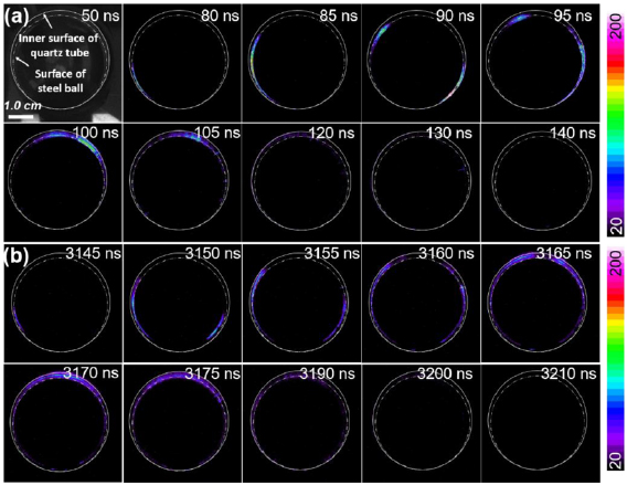
Figure 4. The spatial-temporal evolution of discharge (front view) during the (a) rising and the (b) falling slopes (solid line: inner surface of the quartz tube, dotted line: surface of steel ball). Single shot with the gate width of 5 ns.
Download figure:
Standard image High-resolution imageFigure 5 shows the spatial-temporal evolution of the discharge captured by the ICCD from the side view during the rising and falling slopes. The arrows indicated the development direction of the discharge. During the rising slope of the applied voltage, the discharge was ignited at the bottom of the device (at the small gap region) at ~80 ns and then developed upwards and sidewards (to the large gap region), which exhibited a uniformly 'scanning' pattern. Based on the ICCD measurements, the average development velocity of the discharge was calculated to be ~105 m s−1. The discharge was sustained about 60 ns and extinguished at 140 ns. During the falling slope of the applied voltage, the discharge was ignited at the bottom of the device at 3145 ns, the discharge pattern and the sustaining time were consistent with the discharge during the rising slope. It should be noted that there is a significant difference in the intensity of the discharge during its development. The difference could be explained as follows: with increasing the gap distance, strong electron avalanches were spawned, resulting in increased discharge intensity [28]. When the discharge developed to the top of the steel ball, the emission intensities of the discharge were integrated to the ICCD from the side view (90–130 ns in the rising slope, 3160 to 3210 ns in the falling slope). Different from the randomness of discharge channels generated by plate-to-plate DBD, the development of discharge channel was artificially controllable. Discharge channel was ignited in the place where the air gap was small. With the increase of the applied voltage, the discharge channels developed regularly from the small air gap to the large air gap.

Figure 5. The spatial-temporal evolution of discharge channels (side view) during the (a) rising and the (b) falling slopes (solid line: inner surface of the quartz tube, dotted line: surface of the steel ball). Each image was taken once with the gate width of 5 ns. The arrows indicate the development direction of the discharge.
Download figure:
Standard image High-resolution imageAn electric field simulation with the same structural parameters as the experiment was used to verify that the development of the discharge. The simulation showed that the development of the discharge was related to the distance of the electrode gap. The potential of the H.V. electrode was set to a constant value of 20.0 kV. It should be noted that, the calculation was carried out without plasma. In figure 6(a), a 3D distribution of the electric field in the space is given. The solid line represents the outer surface of the quartz tube and the dotted line represents the inner surface of the quartz tube. The electric field induced by the applied voltage showed an uneven distribution in the whole space, and the norm value of the electric field showed a rapid diminishing trend from the axis of the steel ball to the both sides of the space. In order to observe the distribution of the electric field over the surface of steel ball, the distribution of the electric field over the surface of steel ball from the side view is given in figure 6(b). The electric field over the surface of the steel ball in the axial direction gradually decreases from the bottom of the steel ball to the top of the steel ball, and the electric field was gradually reduced from the axis to both sides of the steel ball. As the distance of the air gap increased from 0 to 1 mm, the electric field significantly decreased since the gap distance greatly increases. The norm value of the surface electric field on the bottom of the steel ball was 7.7 log10 V m−1, which was 0.7 log10 V m−1 higher than that of the surface electric field on the top of the steel ball. From the side view, the minimum value of the surface electric field on both sides of the steel ball was 6.2 log10 V m−1, which was 1.5 log10 V m−1 lower than that of the maximum value. The discharge was firstly ignited in the small gap region where the electric field was relatively intense. With the increase of the applied voltage, the breakdown electric field was achieved and the discharge developed to the large gap region.
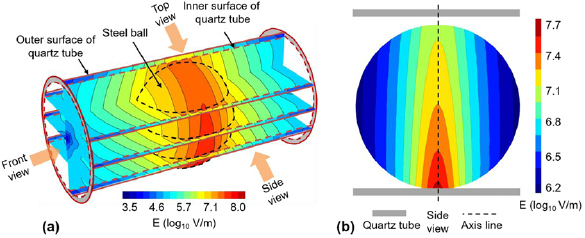
Figure 6. The distribution of electric field in the space (a) and over the surface of the steel ball (b) (solid line: outer surface of the quartz tube, dotted line: inner surface of the quartz tube).
Download figure:
Standard image High-resolution imageThe generation and extinction mechanism of discharge during rising and falling slopes is schematically shown in figure 7. In our case, when the applied voltage increased to 8.3 kV, the discharge was ignited in the small gap region (figure 7(a)). The electrons on the cathode surface drifted along the opposite direction of the E0 in the air gap. The electron avalanche multiplication occurred when electrons gained enough energy to ionize or excite neutral atoms or molecules in the air gap [24]. When the electron avalanche developed from the cathode to the surface of the quartz tube, a discharge channel was formed, and the space charge was transported to the quartz tube and accumulated on the surface of the tube. Due to the surface charge accumulation, an electric field was built in the opposite direction of the applied electric field (Region1, figure 7(b)). The establishment of the reverse electric field led to a rapid decrease of the electric field strength in the discharge channel. The discharge was extinguished when the superposed field cannot maintain the discharge. In the same position, a second breakdown occurred in the original position only when the voltage in the air gap rose again to the initial air gap breakdown voltage. In this study, the minimum voltage for igniting discharge during the rising slope was 8.3 kV, however, no secondary discharge was observed with increasing the applied voltage to 18.5 kV (figure 3(b)). The charge accumulated on the surface of quartz tube per unit area is defined as Q(s,t):

where Cd is the capacitance value of quartz tube, Q(s,t) is the amount of charge accumulated on the surface of quartz tube per unit area, Ua(t) is the applied voltage, Ug(s,t) is the voltage across the air gap. Q(s,t), Ua(t) and Ug(s,t) are functions of time.
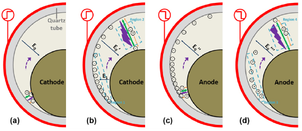
Figure 7. Generation and extinction mechanism of discharge channels during (a), (b) rising and (c), (d) falling slopes. (Front view; E0: direction of total electric field in air gap; E1: reverse electric field formed by surface charge accumulation.)
Download figure:
Standard image High-resolution imageFor the current design, Ug(s,t) was determined by the distance of air gap. After charges were accumulated, the capacitance of the quartz tube remained unchanged.  increased with increasing
  . At a given
  , the larger the air gap, the larger the
  , resulting in a smaller
  . Therefore, the smaller the air gap, the greater the amount of charge accumulated on the surface of quartz tube. The accumulation of surface charge on the surface of quartz tube was uneven. With the increase of air gap, the less charge accumulated on the surface of quartz tube per unit area (figure 7(b)). The accumulated charges which may flow along the surface would generate a strong reverse electric field. The reverse electric field would prevent the occurrence of secondary breakdown.
The micro-discharge of a unipolar high voltage pulse at falling slope was generally recognized as being caused by a reverse electric field generated by the charge accumulated on the surface of the dielectric [29, 30]. The former anode was 'converted' to be the cathode due to the negative surface charge. When the voltage provided by the E in the air gap reaches the breakdown voltage of the air gap, the discharge was ignited. Electrons accumulated on the surface of quartz tube were transferred to the anode under the action of E (figure 7(c)), and neutralized with the positive charge in space during development, which eventually led to the decrease of the number of negative charge accumulated on the surface of quartz tube, the reducing of the E intensity generated in the air gap, and finally the extinction of discharge (Region3, figure 7(d)). For unipolar positive pulse discharge, the length of pulse width has a significant effect on the generation of discharge channel at the falling slope, and the detailed work has been reported [29].
3.2. Control of pathogenic microorganisms on fruit surface by an atmospheric pressure air DBD system
As shown in figure 2, S. aureus was inoculated at five specific locations on the apricot surface. The inoculation concentration of S. aureus at each special location on the apricot surface was ~7 log10 CFU cm−2. The plasma treatment time of the fruit in static state and rolling state (Fruit rolls in one direction at a constant speed in the device) was 15 s. Due to the different discharge intensity on five specific locations, the bactericidal effects of the apricot induced by ACP may result in different performances. When the apricot was treated by plasma in static state, the survival numbers of bacterial on A, B, C, D and E decreased from 7 to 3.28, 2.11, 1.82, 2.83 and 3.19 log10 CFU cm−2, respectively (figure 8). When the apricot was treated by plasma in rolling state, the survival number of bacteria at different locations on the apricot surface was significantly decreased. The distance of air gap increased from location A (E), B (D) to C. The larger the air gap was, the longer the development of the electron avalanche, leading to the high the concentration of active species generated by plasma, such as singlet oxygen, super oxygen anion etc. Besides, the plasma treatment time was inconsistent for different locations of the apricot surface. As shown in figure 5, discharge was rarely generated in the middle position of the steel ball along the axial direction (A/E location). During the rising slope of the H.V. pulse, the ignition times of discharge at the location of A (E), B (D) and C were 5, 10 and 35 ns, respectively (figure 5). The treatment time play an important role in the plasma sterilization, the bactericidal efficiency of plasma increased with the increase of treatment time [8, 9, 31].
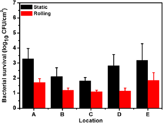
Figure 8. A comparison of the survival number of bacterial at different locations on the surface of the fruit when it is static or rolling.
Download figure:
Standard image High-resolution imageIn the rolling state, the bacterial survival numbers on different locations of A, B, C, D and E decreased from 7 to 1.71, 1.2, 1.1, 1.15 and 1.86 log10 CFU cm−2, respectively. When the apricot is treated by plasma in static state, the development of the plasma is limited by the distance and hence some areas on the gauze cannot be directly exposed to the plasma. With the apricots rolling in the device, uniform plasma could be generated over each part of the gauze, and the bactericidal efficiency was greatly improved.
Figure 9 presents the ICCD images captured while the steel ball with a diameter of 45 mm or 38 mm was rolling in the device. The relative sizes of the steel ball in the device are illustrated in figures 9(a) and (b). The ICCD images were taken in single shot mode with a gate width of 1.0 s. Figure 9(c) shows the corresponding discharge image with the steel ball of diameter of 45 mm. With the ball rolling in the device, plasma could be uniformly generated over the ball. The discharge image with the steel ball of diameter of 35 mm is shown in figure 9(d). The discharge was only generated at the bottom of the plasma device, and the discharge intensity was obviously decreased. By contrast, it was apparent that when large steel ball rolling in the plasma device, intense and uniform plasma could be generated. The size of the steel ball had a significant effect on the uniformity of the plasma in such a device. The more suitable the size of the steel ball, the smaller the air gap will be. According to Paschen's law, the smaller the distance of the air gap, the easier the breakdown occurred, thus the uniform plasma in the space could be obtained.

Figure 9. ICCD images of spatial uniformity of plasma produced by different steel ball sizes taken from side view in rolling state (a) diameter (D): 45 mm; (b) D: 38 mm (single shot with gate width of 1 s).
Download figure:
Standard image High-resolution imageFigure 10 shows the survival numbers of bacteria on apricot surface with different size treated by plasma in rolling state at five specific locations. When the height of the apricot is 4.4 cm and the width is 4 cm (larger one), the bacterial survival numbers on A, B, C, D and E decreased from 7 to 2.39, 1.79, 1.34, 1.86 and 2.47 log10 CFU cm−2, respectively. When it came to the apricot of 3.1 cm tall and 2.9 cm wide (smaller one), the bacterial survival numbers on A, B, C, D and E decreased from 7 log10 to 4.37, 3.31, 2.18, 3.46 and 4.14 log10 CFU cm−2, respectively. At the same location on the surface of apricot with different sizes, the survival numbers of bacteria were significantly different. For the same inoculated area, the survival number of bacteria on the surface of large apricot is significantly lower than that of small apricot. In the practical industrial application of the device, it is very important to select the appropriate inner diameter of quartz tube according to the size of apricot.
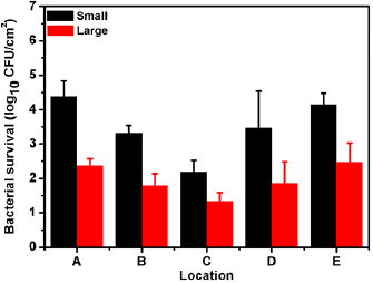
Figure 10. Effect of apricot sizes on the survival numbers of bacteria on apricot surface treated by plasma in rolling state.
Download figure:
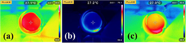
Standard image High-resolution imageFigure 11 shows the infrared thermal images of the apricot before, during and after the plasma treatment for 15 s in rolling state. The temperature of the apricot surface increased from 27.1 °C to 27.9 °C after the plasma treatment, showing that the plasma treatment had no vital impact on the apricot surface temperature. In figure 11(b), the discharge between the ground electrode and the surrounding high voltage electrode resulted in the temperature of 79.1 °C around the ground electrode. However, the change in the apricot surface temperature was not significant as the apricot kept rolling in the device within 15 s.
Figure 11. Infrared thermal imaging measurement of apricot surface temperature (a) before plasma treatment, (b) during plasma treatment, (c) after 15 s rolling plasma treatment.
Download figure:
Standard image High-resolution image
4. Conclusion
The characteristics of a novel atmospheric pressure air DBD device had been studied to generate plasma directly on the surface of fruit. A banded discharge channel was formed between the surface of steel ball and the inner wall of quartz tube, presenting a 'scanning' development along the steel ball surface. The breakdown occurred from the small gap region to the large gap region; meanwhile, the discharge was self-extinguished from the small gap region to the large gap region due to charge accumulation on dielectric surfaces. The development of discharge can be artificially controlled by controlling the distance of air gap. Plasma treatment can significantly reduce the survival number of pathogenic microorganisms on the surface of apricot under rolling state without causing thermal damage to the fruit surface. Compared with the initial bacterial concentration, the number of S. aureus on the surface of 1 cm2 decreases by 5.9 log10 CFU after plasma treatment of rolling fruit for 15 s. The plasma device designed in this study has the practical application for the rapid removal of pathogenic microorganisms on the surface of postharvest fruits.
Acknowledgment
This work was supported by the National Science Foundation of China under Grant No. 11905094 and scientific research funding of Liaoning Provincial Department of Education under Grant No. LQ2019021. Discussions with Professor Jialiang Zhang are gratefully acknowledged.