
Abstract
The flexural behavioral properties of ultra high performance concrete (UHPC) low-profile T-beams reinforced with a combination of steel fibers and steel reinforcing bars were investigated in this paper. Five large scale T-beams were tested and analyzed regarding their deflection, ductility, strain, curvature, load capacity and crack development. The experimental variables include the reinforcement ratio, the slenderness (length to diameter ratio) of the fiber reinforcements, and the fiber type. The experiments showed that all specimens exhibit flexural failure with the yielding of steel bars and excessive expansion of flexural crack, and the compression zone in the reinforced UHPC low-profile T-beam is not crushed because of the ultra high compressive strength and area of UHPC. In addition, it was concluded that using hooked-end fibers can effectively increase the specimen’s durability-based cracking load in comparison to straight fibers of same slenderness, whereas the reinforcement ratio and the slenderness of the fibers have little influence on this. Increasing the reinforcement ratio and using hooked-end instead of straight fibers increase the load capacity and bending stiffness of the specimen, as well as reduces the crack width at comparable applied load. A model was established to compute the ultimate capacity of UHPC low-profile T-beams and the prediction agrees well with the experimental results in the present and published investigations.
1 Introduction
Ultra high performance concrete (UHPC) is characterized by high particle packing density and low matrix porosity achieved by a low water-to-cementitious material ratio (generally below 0.25). UHPC is made of well graded cementitious materials and fine aggregate. The addition of superplasticizers allows for an effective dispersion of fine particles which is necessary to mix the concrete at a low water-to-cementitious material ratio. The addition of fibers with tailored tensile strength, bond properties and volume fraction significantly enhances the concrete’s tensile strength, ductility and toughness. Compared with normal concrete (NC) or high performance concrete (HPC), UHPC exhibits higher strength, toughness, and durability, and lower creep coefficient and shrinkage after heat curing (Graybeal 2005, 2006a, b). Fiber volume fraction, fiber shape, fiber slenderness (length to diameter ratio), fiber orientation affected by the concrete placing method and specimen dimension are most influential on the tensile behavior and thus on its ductility, fracture toughness, and energy absorption capacity (Kang et al. 2011; Nguyen et al. 2013; Wille and Parra-Montesinos 2012). As a result, fibers play an important role in affecting the mechanical properties of UHPC and thus its flexural behavior.
In the past decade, many researchers have investigated the effect of fiber properties [i.e., dosage (Yoo et al. 2013), aspect ratio (Yoo et al. 2014a, 2016b), shape (Kim et al. 2011; Wu et al. 2016), orientation (Kang et al. 2011), etc.] on the flexural behavior of UHPC, and most of them emphasize on the material level than the component level (Kim et al. 2011; Wu et al. 2016; Yoo et al. 2013, 2014a, 2016b). At the component level, the flexural behaviors of UHPC beams reinforced with rebars have also been widely studied up to now (Chen et al. 2018; Hasgul et al. 2018; Kahanji et al. 2017; Kamal et al. 2014; Randl et al. 2013; Yang et al. 2010, Yoo et al. 2016a). Yang et al. (2010) conducted an experimental study on the flexural behavior of UHPC beams with rectangular sections, taking the reinforcement ratio and the placing method into account, and they reported that all test beams exhibited ductile performances with ductility index ranging between 1.60 and 3.75. Yoo et al. (2016a), Chen et al. (2018) and Hasgul et al. (2018) have also conducted similar investigations to study the flexural behavior of UHPC beams with various reinforcement ratios, and found that the post-cracking stiffness and load carrying capacity were increased, whereas first cracking load was decreased. Randl et al. (2013) performed the study on the flexural performance of UHPC beams reinforced with different combinations of fibres (0% and 2% by volume) and high grade steel bars, and noted that the incorporation of 2% by volume of steel fibers increases the load bearing capacity by about 15% on average. They also concluded that the combination of steel fibers and high grade steel is promising. Kahanji et al. (2017) studied the structural performance of UHPC beams with different fiber content (1, 2 and 4% in volume). They reported that a minor difference was observed in the deformation and flexural behavior of beams with fiber contents of 1% and 2% in volume, whereas beams with 4% (in volume) fibers exhibited a higher flexural capacity. Moreover, Kamal et al. (2014) compared the effect of steel fiber and polypropylene fiber on the flexural behavior of UHPC beams and indicated that using fibers (steel fiber or polypropylene fibers) could enhanced the behaviors of the tested beams.
All of the foregoing studies on flexural behavior of UHPC beams at the component level are restricted to the effect of reinforcement ratio (Chen et al. 2018; Hasgul et al. 2018; Yang et al. 2010; Yoo et al. 2016a), fiber orientation (Yang et al. 2010) and fiber content (Kahanji et al. 2017; Randl et al. 2013). As far as we know, there are few works on the study about reinforced UHPC beams with various fiber lengths (Qi et al. 2018; Yoo and Yoon 2015) and fiber shapes (hooked-end fiber in special).
On the other hand, all the previous works about the flexural behaviors of UHPC beams only focus on the rectangular section and do not include T-section in general or low-profile T-shape section in specific. The low-profile T-shape beam is mainly used in the UHPC waffle deck panel, which consists of a thin slab cast integrated with concrete ribs in both transverse and longitudinal directions. Several applications (Aaleti et al. 2013; Kong et al. 2016; Park et al. 2012) indicate that the UHPC waffle deck slab has the similar ultimate load capacity, but 30% to 40% lighter than a solid full-depth panel made of conventional concrete, which is significantly beneficial to the application in large span bridges. Hence, it is quite necessary to fully understand the structural performance of low-profile T-shape beams.
The purpose of this paper is to experimentally investigate the flexural behavior of UHPC low-profile T-beams with rebars reinforcement. The experimental parameters under investigation include the ratio of steel rebars, the aspect ratio of fiber and the fiber shape. Lastly, to predict the ultimate loading capacity of UHPC low-profile T-beams, a simplified mechanical model was developed based on the experimental results.
2 Program of Experiment
2.1 Experimental Materials
In this investigation, the mixture proportions of UHPC are present in Table 1. Type I Portland cement, flyash, silica powder and silica fume are used as binders for the UHPC mix design. Quartz sand with particle sizes of smaller than 0.9 mm is added as fine aggregate. The apolycarboxylate-based high-range water-reducing admixture (HRWRA) is used at the amount equal to 2% of the binder mass to increase the workability of the concrete. In order to investigate the effect of the aspect ratio and shape of steel fiber on the flexural performance, three varied aspect ratios (i.e., 65, 81 and 83) for straight steel fibers (S) and one hooked-end steel fiber (H) with the aspect ratio of 65, are considered at volume fraction of 2%. The steel fibers are generally divided into two types: (1) straight steel fiber (SX) and (2) hooked-end steel fiber (HX). It should be noted that the notation S, H and X indicate the straight fiber, hooked-end fiber and fiber’s aspect ratio, respectively. For example, S65 is the UHPC mixture with straight steel fibers at an aspect ratio of 65. The detailed dimensions of the steel fibers are shown in Table 2.
2.2 Details of the Specimens
In this paper, five full-scale UHPC low-profile T-shape beams, whose dimensions are similar with UHPC deck slab in reference (Kong et al. 2016), are fabricated for the experimental program. In the reference (Kong et al. 2016), the scheme of steel-UHPC lightweight composite girders in Shengtian Bridge, a cable-stayed bridge with the span of 181.95 m + 450 m + 181.95 m, were proposed. In the scheme, the deck slab of composite girders was specially designed as the UHPC deck panel with low-profile ribs, as shown in Fig. 1. The height of the UHPC deck panel with low-profile ribs is 220 mm. The UHPC deck panel consists of a thin flat plate and low-profile ribs. The thickness of the thin flat plate is 80 mm. The height and transverse spacing of the ribs are 140 mm and 700 mm, respectively. The width of the ribs is set to be 180 mm at the bottom with a slight increase to 200 mm at the top of the rib at the interface of rib-to-plate.

Scheme of steel-UHPC composite girder [unit: mm, in reference (Kong et al. 2016)].
The details of dimension and reinforcement for the specimens are given in Fig. 2. To ensure the flexural failure mode for the specimens, adequate shear reinforcement with a diameter of 6 mm is arranged with the spacing and a clear cover of 150 mm and 20 mm, respectively. Meanwhile, the low-profile rib is also reinforced with longitudinal rebars at both the top and the bottom. The strength grade of all the rebars is accepted as HRB400.

Details of the specimens (unit: mm).
The details of the parameters, including the reinforcement ratio, the fiber length to diameter ratio and the shape of the fiber, are list in Table 3. It should be known that the specimens are distinguished with the fiber type and longitudinal reinforcement. For instance, B-S65-16 denotes the specimen including straight steel fibers with an aspect ratio of 65 and steel rebar with a diameter of 16 mm. The longitudinal rebars in the cross section are set at the distance of 35 mm from the bottom surface of the specimen.
2.3 Fabrication of the Specimens
The low-profile T-beams were fabricated in both groups. The first group (Group I) includes four specimens B-S65-16, B-S65-20, B-S81-20 and B-S83-20, while the second group (Group II) only contains B-H65-20. Taking the first group as an example, the process of specimen fabrication is given as follows:
-
1.
The metallic forms of the specimens were manufactured and assembled. After that, the rebars were arranged, as shown in Fig. 3.
Fig. 3 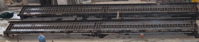
Assembly of the form and arrangement of the rebar.
-
2.
The UHPC was mixed using a forced mixer and then the concrete was placed. A high-frequency concrete vibrator was used to compact the UHPC. A covering membrane was used to aid in the curing process at normal temperature for 48 h, as displayed in Fig. 4.
Fig. 4 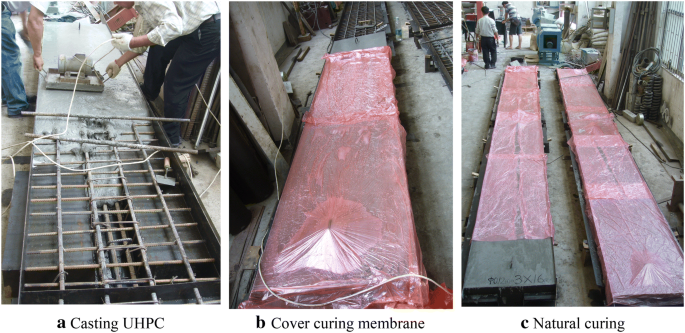
Process of casting UHPC and natural curing.
-
3.
After curing for 48 h, the metallic form was moved. Next, the beam specimens were steam cured at a temperature of 90–100 °C for another 48 h, as shown in Fig. 5.
Fig. 5 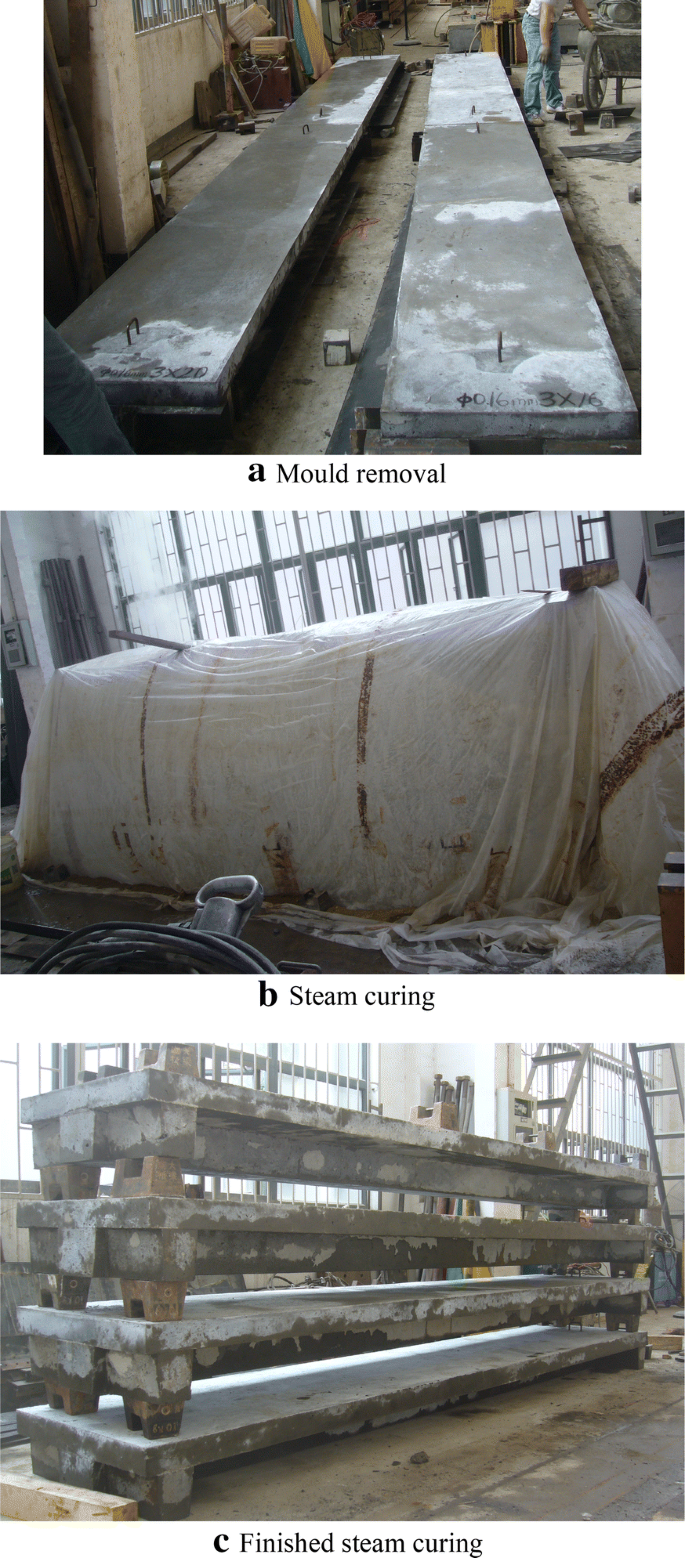
Process of steam curing.


2.4 Material Properties of UHPC and Reinforcement
Twelve cubic specimens with a side length of 100 mm were manufactured (three for each variable) and tested per Chinese code (GB/T 31387 2015). At the same time, 12 prismatic specimens with cross-sectional dimension of 100 mm × 100 mm and lengths of 400 mm, were cast (three for each variable) and tested in flexure per Chinese code (GB/T 31387 2015). In the bending test, the applied load and mid-span deflection were recorded. The loading setup and photograph of the material tests of UHPC are shown in Fig. 6. In addition, the direct tensile test of steel reinforcement was conducted per Chinese code (GB/T 228.1 2010).

Loading scheme and photographs of the UHPC material tests.
The average flexural load–deflection curve with a four-point bending test is illustrated in Fig. 7. The other material properties of UHPC and reinforcement are summarized in Tables 4 and 5, respectively.

Average flexural load–deflection curve.
2.5 Instrumentation and Loading Procedures
Figure 8 indicates the plan of instrumentation for the specimens. In order to measure the strain of steel rebars, six strain gauges with a length of 5 mm were placed at the surface of tension reinforcements. For the sake of obtaining the strain of concrete, 20 mm-long gauges were used to detect the strain of the concrete. In particular, six strain gauges were arranged on the top of the specimen at constant moment region to measure compressive strain, while six strain gauges were also set on the specimens’ bottom surface measuring concrete tensile strain. Meanwhile, two extensometers were positioned at the bottom of the specimens to obtain the tensile strain as well. In addition, three displacement sensors were placed to measure the deflection at mid-span and support. Furthermore, the development of the crack length and width were recorded during the process of the test.

Details of experimental program (unit: cm).
The test setup is illustrated in Fig. 8, and the arrangement of the test loading device and measuring instrument is shown in Fig. 9. The specimens, which are supported on rollers and pins, were loaded in four-point bending, using a single 500 kN jack for the specimens B-S65-16 and B-S65-20 and a PMS-500 digital pulsating fatigue tester under static load conditions for the specimens B-S81-20, B-S83-20 and B-H65-20. To obtain the force of the jack, a 250 kN load cell was installed on a transfer beam supported by rollers and pins. Rollers and pins of the specimen support were set at a distance of 100 mm from the ends of the specimen. The length of a pure bending part was 1.4 m. Each beam test was conducted loading controlled at first, and when the applied load approached to around 75% of peak load, the control method was switched to displacement-control.

Test loading setup.
In order to accurately obtain the cracking load and peak load, a smaller loading rate was set when the applied load approximates the cracking load and peak load. After cracking load, the loading rate was increased due to the UHPC members’ satisfactory post-cracking capacity. The loading procedure continued until the maximum crack width of UHPC beams is more than 4 mm or the specimen was found to be softened.
3 Experimental Results and Discussions
3.1 Load versus Deflection Response
3.1.1 General Flexural Behavior
The experimental load was plotted against the vertical displacement at mid-span of all reinforced UHPC low-profile T-shape beams in Fig. 10. In addition, the load and corresponding deflection at first cracking, yielding of rebars reinforcement and ultimate load are listed in Table 6.

Load mid-span displacement curves of the specimens.
As observed in Fig. 10, the load–displacement curve for the reinforced UHPC low-profile T-beams is divided into three stages: elastic stage, crack development stage and yield strengthening stage. In the elastic stage, the flexural stiffness of the specimen is provided by the un-cracked UHPC and the reinforcement, resulting in a linear load versus displacement curve. Increasing the load beyond the elastic limit at about 40 kN resulted in the sufficient development of micro-cracks in the UHPC. This cracking load appears as a linear deviation point on the load–displacement curve (Yang et al. 2010; Yoo and Yoon 2015; Chen et al. 2018), and visible cracks (crack width: 0.02–0.05 mm) appear in the weak zone of the constant bending moment section (Qi et al. 2018). Meanwhile, the decrease of the slope of the load–displacement curve is found, implying that the bending stiffness of the beam decreases, which indicates that the beam enters the crack development stage. This is confirmed by the observation that the cracks’ width and number increase. As the load increased to the yield load, a new inflection point is found in the load versus displacement response, defined as the yield load (Yang et al. 2010; Yoo and Yoon 2015; Chen et al. 2018), and the specimen starts the yield strengthening stage. At this stage, it is observed that the load increased slowly with significant increase in displacement. Meanwhile, some of the initial flexural cracks transformed into main localized cracks, followed by a rapid increase in the crack width. With the increase of the load, the displacement of the specimen continues to increase, which indicates the excellent ductility of the reinforced UHPC beam with a displacement ductility index (μ = Δu/Δy) of more than 1.27. Due to the ultra high compressive strength of UHPC and large flange area of T-beam, at the peak load, the specimen in the compression zone is not crushed and the corresponding compressive strain at the top flange of the specimen is about 1300 με (as shown in Fig. 12). The peak load is therefore taken as the ultimate load.
3.1.2 Reinforcement Ratio
Figure 11a depicts the load–displacement curves of the reinforced UHPC low-profile T-beams (B-S65-16 and B-S65-20) with the same fiber characteristics and different reinforcement ratios. In the elastic stage, the flexural stiffness of the beam specimens slightly increased when the ratio of reinforcement increased. As for the crack development stage, the effective bending moment of inertia (which was used to qualitatively express the post-cracking stiffness of the specimens) and the ultimate loading capacity of the specimens increased significantly with the increase of the reinforcement ratio. Compared with the specimen B-S65-16, an increase of 56.3% in the ratio of reinforcement resulted in an increase of yielding load by 60.2% and ultimate bearing capacity by 55.3% (B-S65-20), respectively. These results demonstrated that the longitudinal reinforcement not only played a significant role in the pre-cracking and post-cracking stiffness of reinforced UHPC low-profile T-beams but also as expected improves their yielding load and ultimate bearing capacity. However, when the reinforcement ratio increase from 0.73% to 1.14%, the cracking load slightly decreased by 6.5%. This is because higher reinforcement ratios could result in higher residual tensile stresses due to the constraint of autogenous shrinkage of UHPC (Yoo et al. 2014b; Yoo and Yoon 2015).

Load mid-span displacement curves of the specimens: (a) different reinforcement ratios; (b) different fiber lengths; (c) different fiber shapes.
3.1.3 Fiber Length
Figure 11b shows the load–displacement curves of reinforced UHPC low-profile T-beams (B-S65-20, B-S81-20 and B-S83-20) with the same reinforcement ratios and various ratios of fiber length to diameter. It can be found that the specimens with different length to diameter ratios all exhibit similar load versus displacement behavior across the three stages. This illustrates that the fiber ratio of length to diameter in the range investigated here has no noticeable effect on the stiffness and ultimate bearing capacity of the reinforced UHPC low-profile T-beams. This is different from the material level results in UHPC, where an increase in the fiber slenderness can increase the ultimate bending strength (Yoo et al. 2014a, 2016b). This might be explained that the limited change in UHPC tensile behavior due to the change in fiber slenderness has no significant effect on the reinforced UHPC behaviors.
3.1.4 Fiber Shape
In addition, the load–displacement curves of reinforced UHPC low-profile T-beams (B-S65-20, B-H65-20) with the same reinforcement ratios but different fiber shapes are plotted in Fig. 11c. In the elastic stage, the specimens exhibit with similar flexural stiffness. However, in the crack development stage, contrasted to the specimen with straight fibers (B-S65-20), the specimen with hooked-end fibers (B-H65-20) had a larger effective bending stiffness and a higher ultimate bending capacity, which was approximately 1.4 times that of the specimen with straight fibers. The results indicated that the fiber shape had little influence on the pre-cracking stiffness of UHPC beams but can effectively improve the post-cracking stiffness and ultimate bending capacity. The primary reason can be attributed to the additional mechanical anchorage and thus increased the bond strength of hooked-end fibers to the UHPC matrix in comparison to straight fibers (Wille and Naaman 2012; Yoo and Kim 2019), and thus the flexural strength and tensile behavior (i.e. ultimate tensile strength and corresponding strain) were effectively improved (Wu et al. 2016; Wille et al. 2011; Park et al. 2012), which was of great benefit to enhance the post-cracking stiffness and flexural capacity of the specimen.
3.2 Ductility
Conventionally, the ductility of flexural members is evaluated by a ductility index from the point of deflection ductility index (Qi et al. 2018; Yang et al. 2010; Yoo and Yoon 2015), curvature ductility index (Lee and Pan 2003), or rotational ductility index (Samir and Faisal 1993). The deflection ductility index would be preferred to be accepted due to its convenience. In this investigation, the deflection ductility index, as illustrated in Eq. (1), was adopted to determine the ductility of the specimens.
where Δu is the ultimate deflection and Δy is the yielding deflection.
Recently, Qi et al. (2018) also proposed the following formulation to evaluate post-cracking deflection ductility:
where Δcr is the cracking deflection.
The ductility indices of specimens obtained with Eqs. (1), (2) are listed in Table 6. Fiber length to diameter ratio had no considerable influence on the post-cracking ductility for reinforced UHPC low-profile T-shape beams. However, fiber shape showed a remarkable effect on the post-cracking ductility, which demonstrates the efficiency of the usage of hooked-end fibers. In addition, the effect of increasing reinforcement ratio resulted in the decrease of the deflection ductility index, which is in accordance with the other investigation by Yoo and Yoon (2015) and Qi et al. (2018).
3.3 Load Versus Strain Response
3.3.1 Concrete Strains
Figure 12 shows the strain of the extreme compression fiber and extreme tension fiber at the constant bending regions in relation to the experimental load. Positive values present extreme tension strains of the bottom surface of the specimens, and negative values denote the extreme compression strain of the top surface of the specimens. Before the appearance of visible flexural cracking (0.05 mm crack width), both extreme compression strain and extreme tension strain exhibited a small value and kept linearly. When the visible flexural cracks appear, the tensile strains increased significantly as expected. Interestingly, no extensively crushing was observed in the concrete at the extreme compression fiber of the specimen since the maximum compressive strains with about 1300 με are significantly less than the ultimate compressive strain of UHPC (fc/Ec ≈ 3000 με). As a result, it is acceptable to assume a simplified linear elastic behavior in the calculation of the bending capacity of the UHPC specimens (SIA 2052 2016).

Load versus top and bottom surface concrete strains of pure bending regions: (a) different reinforcement ratios; (b) different fiber lengths; (c) different fiber shapes.
Specifically, it can be found in Fig. 12a that the compressive and tensile strain at the post-cracking phase decreases significantly with the increase of reinforcement ratio, which is similar to regular reinforced concrete beams. Moreover, while Fig. 12b shows that fiber slenderness has no significant effect on the strain values at the same load, Fig. 12c indicates that the usage of hooked-end fiber can effectively reduce the compressive and tensile strain of the specimens at the post-cracking phase. This is due to the fact that the effective moment of inertia of the specimen at the crack development stage could be significantly enhanced by the usage of hooked-end fibers.
3.3.2 Reinforcement Strains
Figure 13 shows the load versus reinforcement strain curves of all specimens. The strain values were obtained by strain gauges, which were attached to the center of the rebar reinforcement in the tensile zone of the specimen in constant bending region. The load–reinforcement strain curves are also divided into three stages, which is similar to the load–displacement curves. At first, the load-strain relationship exhibited linear behavior before the generation of visible cracks. After visible cracking, the tensile strain of concrete was borne by the rebar reinforcement and the fibers bridging the cracked sections. The strain of reinforcement strain still increased linearly with the applied load, whereas the strain’s increase rate accelerated until the longitudinal reinforcement yielded. When the rebar reinforcement is yielding, the strains of rebar reinforcement increased significantly and deformation of the specimen also considerably increased, whereas the corresponding load nearly kept unchanged.

Load -reinforcement strains curves of the specimens.
In addition, Fig. 13 also displays the selected reinforcement strain (500 με, 1000 με, 1500 με and 2000 με) of all specimens. Specifically, it can be found from Fig. 13 that compared with specimen B-S65-16, the corresponding load of B-S65-20 with the same reinforcement strain increased by at least 38%. In another word, the stress of reinforcement, especially at the post-cracking phase, can effectively be reduced by increasing the reinforcement ratio, which is beneficial to control the crack width of the UHPC (NF P18-710 2016b). In addition, Fig. 13 indicates that the usage of hooked-end fiber leads to higher load values at the same strains, and thus reduces the reinforcement strain of the specimens after cracking at the same load. This is because the effective moment of inertia of the specimen at the crack development stage could be effectively improved by the utilization of hooked-end fibers. However, Fig. 13 illustrates that the reinforcement strain in the specimens with various fiber lengths is nearly similar, which demonstrates the fact that the fiber length has little influence on the reinforcement strain of the specimens. This might be attributed to the fact that little difference in UHPC tensile behavior, resulting from the change in fiber slenderness, has no significant effect on the reinforced UHPC behaviors.
3.4 Bending Moment Versus Curvature Relationship
To obtain the curvature of the specimens, the strain gauge values prior to severe cracking of the underlying concrete were applied to generate a strain distribution of the specimen. The strain distribution was used to determine the section’s curvature for the reason that the plane-section assumption was assumed to be valid.
Figure 14 indicates the moment–curvature curves at constant bending regions of the specimens. The moment versus curvature curves can be divided into three stages, which are similar to the load versus displacement curves. The moment–curvature relationship behaves linearly until about 1.5 × 10⁻⁶/m. At this curvature, with the appearance of visible cracks, the corresponding load and bending moment are about 40 kN and 21 kNm, respectively. The moment versus curvature curves exhibit nonlinear behavior over this curvature, and the curvature developed less significantly for the specimens with higher reinforcement ratio, as shown in Fig. 14a. Meanwhile, with the same values of moment, the curvature of specimen B-H65-20 was less than that of specimen B-S65-20, as displayed in Fig. 14c. However, Fig. 14b indicates that the curvatures of the specimen with different fiber lengths (B-S65-20, B-S81-20 and B-S83-20) were similar for the same level of bending moment.

Bending moment–curvature curves of the specimens: (a) different reinforcement ratios; (b) different fiber lengths; (c) different fiber shapes.
3.5 Crack and Failure Patterns
3.5.1 Cracking Performance and Failure Patterns
The typical crack patterns for the specimen (B-S65-20) at various stages are shown in Fig. 15. The first micro-crack appeared at the extreme tension fiber of the specimen at constant bending moment region, and the first cracks were barely visible. With the increase of the applied load, new micro-cracks were developed between the existing cracks, and Most of them slightly expanded towards the top surface of the specimen. Meanwhile, the cracks expanded with very limited increment, whose propagation rate is much lower than the flexural cracks in normal reinforced concrete beams (Borosnyoi and Balazs 2005; Chiu et al. 2018; Gribniak et al. 2016). This is attributed to the fact that the fibers, bridging the gap between the crack surfaces, are effectively restrained the expansion of flexural cracks width. The experiments also indicated that the specimen exhibit with multi-cracking behavior and flexural cracks formed with tight spacing.

Crack patterns of B-S65-20 at various stages (unit: cm).
As the experimental load was higher than the yield load of the specimen, the fibers located at one specific section were gradually pulled out, leading to the crack localization with significant increase of crack width. It is because of the local bond failure between fiber and the UHPC matrix as well as rebars yielding. When the applied load approached to the peak load of the specimen, the crack localization with excessive crack width (i.e. higher than 4 mm) and rebars yielding was observed, and thus the specimen was regarded as failure in this investigation.
3.5.2 Durability-Based Cracking Stress
According to the investigation of Rafiee (2012), when the crack width of UHPC is smaller than 0.05 mm, UHPC exhibits as a sound concrete in terms of durability. As a result, the design criteria with durability-based UHPC crack width may be more promising in actual structure application (Pan et al. 2016). The assumptions of linear elastic theory are still valid since the stiffness of the specimens nearly keeps unchanged in the micro-cracking stage (Pan et al. 2016; Chen et al. 2018). Hence, durability-based cracking stress is adopted to the nominal tensile stress with a crack width of 0.05 mm.
Figure 16 summarizes the nominal stress histogram for the specimens with a crack width of 0.02 mm (micro-crack) and 0.05 mm. In Fig. 16, when the crack width is 0.02 mm for all specimens, the nominal stress is between 7 MPa to 9 MPa, which approximate the elastic limit tensile strength of UHPC. This outcome indicates that the reinforcement ratio, the fiber length to diameter ratio and fiber shape have little influence on the cracking load of micro-cracks, which is consistent with other investigation (Yoo and Yoon 2015).

Nominal stresses of the specimens with 0.02 mm and 0.05 mm crack width.
The load at the critical crack width of 0.05 mm was approximately 40 kN for all straight fiber specimens B-S65-16, B-S65-20, B-S81-20, and B-S83-20, corresponding to the nominal cracking stress of approximately 10.5 MPa. However, the load of the hooked-end fiber specimens (B-H65-20) at a crack width of 0.05 mm was 65.2 kN, and the corresponding nominal stress was up to 17.31 MPa, which was increased by about 63% compared to the straight fiber specimens. This indicated that the reinforcement ratio and the length to diameter ratio of straight fibers of the UHPC beams have little effect on the durability-based cracking load of the UHPC low-profile T-beams, while the fiber shape, and thus the mechanical anchorage, has a significant effect on the durability-based cracking load of reinforced UHPC low-profile T-beams.
3.5.3 Propagation of Crack Width
Figure 17 indicates the load versus maximum crack width curves of the specimens. As previously mentioned, the maximum crack widths of the specimen increased linearly with the increase of the applied load initially, and the localization of cracking resulted in rapid increases of the maximum crack width after yielding of the reinforcement. As shown in Fig. 17, the propagation rate of crack width decreases with the increase of the reinforcement ratio and the employment of hooked-end fibers, whereas the length to diameter ratio of straight fibers has little effect on restricting the crack expansion of UHPC beams. This is mainly because increasing reinforcement ratio can significantly reduce the stress of reinforcement (as demonstrated in Fig. 13), and UHPC can bear more after cracking due to the fact that the hooked-end fibers have a stronger bonding force with the matrix. As a result, the strain difference between steel rebars and concrete could be significantly reduced and the development of crack width is able to be controlled.

Load-maximum crack width curves of specimens.
4 Prediction of the Ultimate Capacity
In the members of normal reinforced concrete, when calculating the ultimate bending capacity, the tensile strength of normal concrete is commonly ignored (fib 2013). However, UHPC exhibits superior post-cracking property since a mass of fibers are activated after the cracking of UHPC matrix, which enable guarantee stress transfer between the cracked surfaces (Yoo and Yoon 2016). As a result, the tensile strength of UHPC should be correctly taken into account in the computation of ultimate bending capacity of UHPC beams (NF P18-710 2016b; JSCE 2004; SIA 2052 2016; Yoo et al. 2016c). Hence, a simplified method is introduced to compute the ultimate bending capacity of reinforced UHPC low-profile T-beams, in which the tensile strength of UHPC is considered.
4.1 Constitutive Model for UHPC and Reinforcement
4.1.1 Compressive Behavior for UHPC
In this investigation, the maximum compressive strain of UHPC at the extreme compression fiber was less than 1400 με (Fig. 12) when the specimen achieved its ultimate load, which was less than the UHPC’s peak strain under compression (fc/Ec ≈ 3000 με). Hence, the distribution of compressive stress of UHPC satisfies a linear behavior in the calculation of ultimate load of UHPC’s beam.
4.1.2 Tensile Behavior for UHPC
In order to obtain the direct tensile stress–strain relationship of UHPC, the inverse analysis of four-point flexural test results (Fig. 7) was conducted based on a previous investigation (Wille et al. 2014), and the direct tensile stress–strain curves from inverse analysis were plotted in Fig. 18. The comparison between experimental and numerical simulation results of four-point flexural test results are given in Fig. 19. The numerical analyses, incorporating direct tensile stress–strain curves from backward analysis, showed a satisfying agreement with the test results. Compared with Figs. 12 and 18, the tensile strain at the bottom surface of the specimens was less than 4000 με (0.4%ε). In order to simplify the calculation of the ultimate capacity, an ideal bilinear stress–strain curve was assumed to conservatively calculate the ultimate capacity of the UHPC low-profile T-shape beams, as shown in Fig. 20.

Direct tensile stress–strain curves for all specimens from inverse analysis.

Inverse analysis and four-point bending test results (inner: direct tensile stress–strain curves from inverse analysis and outer: experimental and numerical results).

Tensile model of UHPC for the calculation of ultimate capacity.
4.1.3 Constitutive Model for Reinforcement
For steel rebars, an ideal elastic–plastic model was assumed to simplify the calculation, as presented in Fig. 21. The yielding strength of the steel rebars is listed in Table 5.

Material model for reinforcement.
4.2 Formulation of Ultimate Capacity
Based on above stress–strain relationships, the distributions of stress and strain at ultimate limit state are shown in Fig. 22. The compressive stress in compression zone is approximately regarded as a triangular distribution, which is consistent with other studies (Leutbecher and Fehling 2013; SIA 2052 2016). Therefore, the resulting force of UHPC in the compressive zone (Fc) acts at the third point from the top of compressive zone. The resulting steel rebars force (Fs) acts at the centroid of the steel rebars. As to the resulting concrete tension force in UHPC (Ft), a uniform tensile stress might be considered to act from the neutral axis to the bottom surface of the tensile zone. Previous investigation indicated that the addition of excessive rebar reinforcement might have a negative effect of fiber orientation and distribution in UHPC (Yoo and Yoon 2015; NF P 18-710 2016b). In addition, there is the elastic un-cracked zone at the real localized crack section. Moreover, in the real localized crack section, the tensile behavior of UHPC might have entered into the strain-softening stage because of the excessive crack width, and thus the ideal bilinear model might overestimate the tensile contribution of UHPC. Thus, in order to consider the aforementioned adverse effect, a strength reduction factor β is introduced, as shown in Fig. 22c. The compressive strength (fc) and direct tensile strength (ft) were taken as the values in Table 4, and the value of yielding strength (fy) of steel rebar was seen in Table 5.

Diagram of the calculation of ultimate load: a cross-section; b strain distribution; c equivalent stress distribution; d equilibrium of forces.
Therefore, when considering the contribution of tensile strength of UHPC, the equilibrium equations of force and moment are given as follows:
Equilibrium of force is
where \( F_{c} = 0.5b_{f} xf_{c} \), \( F_{t1} = \beta f_{t} \left( {b_{f} - b_{w} } \right)\left( {h_{f} - x} \right) \), \( F_{t2} = \beta f_{t} b_{w} \left( {h - x} \right) \), and \( F_{s} = f_{y} A_{s} \).
Equilibrium of moment is
where \( h_{t1} = h_{f} /2 - x/6,\quad h_{t2} = h/2 + x/6,\;{\text{and}}\;h_{s} = h_{0} - x/3 \).
In order to gain the value of the strength reduction factor (β), the experimental ultimate moment (Mu) was substituted into Eq. (4) at first. Then, both Eqs. (3) and (4) were solved in conjunction so that the value of β was obtained and listed in Table 7.
As a result, the following equation can be used to predict ultimate loading capacity of the specimen.
4.3 Experimental Verification
The comparison of experimental ultimate capacity (Mut) with predicted ultimate capacity (Eq. (5), Mup) are present in Table 8, in which β = 0.5 for straight fiber and β = 0.9 for hooked-end fiber. The predicted ultimate capacity agrees well with the experimental results of the UHPC low-profile T-beams, with a mean Mup/Mut of 0.95 and a standard deviation of 0.09. Hence, the proposed equation can well predict the experimental moments in this study.
To further verify the accuracy of the suggested equation for computing the ultimate capacity of UHPC low-profile T-shape beams with straight fiber, similar calculations were also conducted for beams tested in previous investigations (Chen et al. 2018; Qi et al. 2018; Solhmirzaei and Kodur 2017; Yang et al. 2010; Yoo et al. 2016a; Yoo and Yoon 2015). The detailed parameters of test beams in previous studies are tabulated in Table 9, and the calculated and experimental ultimate moments are given in Fig. 23. It can be found that the suggested models agree well with the measured results, with a mean of 0.95 and a standard deviation of 0.09. Therefore, introducing a strength reduction factor (β) to reasonably consider the tensile properties of the UHPC is simple and useful method at the macro level in the prediction of ultimate capacity of UHPC low-profile T-beams with straight fiber. The strength reduction factor β = 0.5 was suitable to the low-profile T-beam with various reinforcement ratio and steel fiber volume fraction of 2.0%. The effect of steel fiber fraction and shape of T-beam on the strength reduction factor (β) should be evaluated in further experimental investigations. However, there is no published literature related to UHPC beams with hooked-end fibers. As a result, the validity of β = 0.9 for hooked-end fiber should be performed in further experimental studies.

Comparison of experimental and predicted ultimate moments.
5 Conclusions
In this paper, static bending performance of the reinforced UHPC low-profile T-beams is investigated experimentally. A formulation was established to predict the ultimate capacity of reinforced UHPC low-profile T-beams. The following conclusions are drawn as follows:
- 1.
The static flexural experiments showed that the flexural behavior of the reinforced UHPC low-profile T-beams is divided into three stages: elastic stage, crack development stage and yield strengthening stage. All specimens exhibited flexural failure with the yielding of steel bars and excessive expansion of flexural crack. Due to the ultra high compressive strength and area of UHPC, the compression zone in the reinforced UHPC low-profile T-beam is not crushed.
- 2.
The increase of the reinforcement ratio can effectively improve the pre-cracking and post-cracking stiffness and bending capacity of the reinforced UHPC low-profile T-beams, and can effectively limit the development of the crack width. However, the reinforcement ratio indicates little influence on the cracking load of the reinforced UHPC T-beams.
- 3.
The length-to-diameter ratio of straight fibers in the range investigated here has little effect on the bending performance of reinforced UHPC low-profile T-beams, such as the cracking load, the pre-cracking and post-cracking stiffness, and the expansion of crack width. However, the fiber shapes with or without hooked-end have demonstrated a larger effect on the bending performance of the reinforced UHPC low-profile T-beams. In comparison to T-beam with straight fibers, the durability-based cracking load and load capacity of the T-beam with hooked-end fibers increase by 63% and 40%, respectively. In addition, the effect of hooked-end fibers on the enhancement of the bending stiffness and the restriction of crack propagation is more significant than that of straight fibers.
- 4.
A formulation was suggested to calculate the ultimate loading capacity of UHPC low-profile T-beams. A strength reduction factor β is introduced to consider the averaging actions of the tensile properties of the UHPC. The prediction models exhibit excellent agreement with the experimental results in the present study and previous literature study, with a mean of 0.95 and a standard deviation of 0.09.
Availability of data and materials
All data generated or analysed during this study are included in this published article.
Abbreviations
- f c :
-
compressive strength of UHPC
- f t :
-
direct tensile strength of UHPC
- f LOP :
-
limit of proportionality of UHPC in the flexural test
- f MOR :
-
flexural strength of UHPC
- f y :
-
yielding strength of steel rebar
- E c :
-
elastic modulus of UHPC
- A s :
-
yielding strength of steel rebar
- Δ cr :
-
deflection at first cracking load
- Δ y :
-
deflection at longitudinal steel rebars yielding
- Δ u :
-
ultimate deflection
- μ cr :
-
post-cracking deflection ductility
- μ u :
-
deflection ductility index
- P cr :
-
first cracking load
- P y :
-
load at longitudinal steel rebars yielding
- P u :
-
ultimate load
- F c :
-
resultant force of the concrete in the compressive zone
- F t :
-
resultant force of the concrete in the tensile zone
- F t1 :
-
resultant force of the concrete in the tensile zone (top flange)
- F t2 :
-
resultant force of the concrete in the tensile zone (web)
- F s :
-
resultant force of the steel rebars in the tensile zone
References
Aaleti, S., Petersen, B., & Sritharan, S. (2013). Design guide for precast UHPC Waffle Deck Panel System, including connections. FHWA-HIF-13-032.
Borosnyoi, A., & Balazs, G. L. (2005). Models for flexural cracking in concrete: The state of the art. Structural Concrete, 6(2), 53–62.
Chen, S., Zhang, R., Jia, L. J., & Wang, J. Y. (2018). Flexural behaviour of rebar-reinforced ultra-high-performance concrete beams. Magazine of Concrete Research, 70(19), 997–1015.
Chiu, C. K., Chi, K. N., & Ho, B. T. (2018). Experimental investigation on flexural crack control for high-strength reinforced-concrete beam members. International Journal of Concrete Structures and Materials, 12(1), 20.
GB/T 228.1-2010. (2010). Metallic materials-Tensile testing-Part 1: Method of test at room temperature, Beijing, China.
GB/T 31387-2015. (2015). Reactive powder concrete, Beijing, China.
Graybeal, B.A. (2005). Characterization of the behavior of ultra-high performance concrete. Ph.D. Thesis, University of Maryland, Maryland.
Graybeal, B.A. (2006a). Material property characterization of ultra-high performance concrete. FHWA-HRT-06-103, N. T. I. Service.
Graybeal, B.A. (2006b). Structural Behavior of Ultra High Performance Concrete Prestressed I-Girders. FHWA-HRT-06-115.
Gribniak, V., Pérez Caldentey, A., Kaklauskas, G., Rimkus, A., & Sokolov, A. (2016). Effect of arrangement of tensile reinforcement on flexural stiffness and cracking. Engineering Structures, 124, 418–428.
Hasgul, U., Turker, K., Birol, T., & Yavas, A. (2018). Flexural behavior of ultra-high-performance fiber reinforced concrete beams with low and high reinforcement ratios. Structural Concrete, 19(6), 1577–1590.
International Federation for Structural Concrete. (2013). fib Model Code for Concrete Structures 2010, Berlin.
JSCE. (2004). Recommendations for design and construction of ultra high strength fiber reinforced concrete structures (Draft), Japan.
Kahanji, C., Ali, F., & Nadjai, A. (2017). Structural performance of ultra-high-performance fiber-reinforced concrete beams. Structural Concrete, 18(2), 249–258.
Kamal, M., Safan, M., Etman, Z., & Salama, R. (2014). Behavior and strength of beams cast with ultra high strength concrete containing different types of fibers. HBRC Journal, 10(1), 55–63.
Kang, S. T., Lee, B. Y., Kim, J.-K., & Kim, Y. Y. (2011). The effect of fibre distribution characteristics on the flexural strength of steel fibre-reinforced ultra high strength concrete. Construction and Building Materials, 25(5), 2450–2457.
Kim, D. J., Park, S. H., Ryu, G. S., & Koh, K. T. (2011). Comparative flexural behavior of hybrid ultra high performance fiber reinforced concrete with different macro fibers. Construction and Building Materials, 25(11), 4144–4155.
Kong, L., Shao, X., & Liu, R. (2016). Finite element analysis of flexural performance of steel-UHPC lightweight composite girder deck. Journal of Highway and Transportation Research and Development, 33(10), 88–95.
Lee, T. K., & Pan, A. D. E. (2003). Estimating the relationship between tension reinforcement and ductility of reinforced concrete beam sections. Engineering Structures, 25(8), 1057–1067.
Leutbecher, T., & Fehling, E. (2013). A simple design approach for UHPFRC in bending. In Int. Symposium on Ultra-High Performance Fibre-Reinforced Concrete (UHPFRC-2013), Marseille, France.
NF P 18-470. (2016a). Concrete—ultra-high performance fibre-reinforced concrete—specifications, performance, production and conformity, Francis de Pressensé, France.
NF P 18-710. (2016b). National addition to Eurocode 2—design of concrete structures: Specific rules for ultra-high performance fibre-reinforced concrete (UHPFRC), Francis de Pressensé, France.
Nguyen, D. L., Kim, D. J., Ryu, G. S., & Koh, K. T. (2013). Size effect on flexural behavior of ultra-high-performance hybrid fiber-reinforced concrete. Composites Part B Engineering, 45(1), 1104–1116.
Pan, W. H., Fan, J. S., Nie, J. G., Hu, J. H., & Cui, J. F. (2016). Experimental study on tensile behavior of wet joints in a prefabricated composite deck system composed of orthotropic steel deck and ultrathin reactive-powder concrete layer. Journal of Bridge Engineering, 21(10), 04016064.
Park, S.Y., Cho, K., Cho, J.R., Kim, S.T., & Kim, B.S. (2012). Structural performance of prestressed UHPC ribbed deck for cable-stayed bridge. In Second International Symposium on Ultra High Performance Concrete, Kassel, Germany.
Qi, J., Wang, J., & Ma, Z. J. (2018). Flexural response of high-strength steel-ultra-high-performance fiber reinforced concrete beams based on a mesoscale constitutive model: Experiment and theory. Structural Concrete, 19(3), 719–734.
Rafiee, A. (2012). Computer modeling and investigation on the steel corrosion in cracked ultra high performance concrete. Ph.D Thesis, Kassel University, Kassel.
Randl, N., Simon, C, & Mészöly, T. (2013). Experimental investigations on UHP(FR)C beams with high strength reinforcement. In RILEM-fib-AFGC International Symposium on Ultra-High Performance Fibre-Reinforced Concrete, Marseilles, France.
Samir, A. A., & Faisal, F. W. (1993). Flexural behavior of high-strength fiber reinforced concrete beams. Structural Journal, 90(3), 279–287.
SIA 2052. (2016). Recommendation: Ultra-high performance fibre reinforced cement-based composites (UHPFRC) construction material, dimensioning und application.
Solhmirzaei, R., & Kodur, V. K. R. (2017). Modeling the response of ultra high performance fiber reinforced concrete beams. Procedia Engineering, 210, 211–219.
Wille, K., Dong, J. K., & Naaman, A. E. (2011). Strain-hardening UHP-FRC with low fiber contents. Materials and Structures, 44(3), 583–598.
Wille, K., & Naaman, A. E. (2012). Pullout behavior of high-strength steel fibers embedded in ultra-high-performance concrete. ACI Materials Journal, 109(4), 479–487.
Wille, K., & Parra-Montesinos, G. J. (2012). Effect of beam size, casting method, and support conditions on flexural behavior of ultra-high-performance fiber-reinforced concrete. ACI Materials Journal, 109(3), 379–388.
Wille, K., Tue, N. V., & Parra-Montesinos, G. J. (2014). Fiber distribution and orientation in UHP-FRC beams and their effect on backward analysis. Materials and Structures, 47(11), 1825–1838.
Wu, Z., Shi, C., He, W., & Wu, L. (2016). Effects of steel fiber content and shape on mechanical properties of ultra high performance concrete. Construction and Building Materials, 103, 8–14.
Yang, I. H., Joh, C., & Kim, B.-S. (2010). Structural behavior of ultra high performance concrete beams subjected to bending. Engineering Structures, 32(11), 3478–3487.
Yoo, D. Y., Lee, J. H., & Yoon, Y. S. (2013). Effect of fiber content on mechanical and fracture properties of ultra high performance fiber reinforced cementitious composites. Composite Structures, 106, 742–753.
Yoo, D. Y., Kang, S. T., & Yoon, Y. S. (2014a). Effect of fiber length and placement method on flexural behavior, tension-softening curve, and fiber distribution characteristics of UHPFRC. Construction and Building Materials, 64(12), 67–81.
Yoo, D. Y., Park, J. J., Kim, S. W., & Yoon, Y. S. (2014b). Influence of reinforcing bar type on autogenous shrinkage stress and bond behavior of ultra high performance fiber reinforced concrete. Cement & Concrete Composites, 48, 150–161.
Yoo, D. Y., & Yoon, Y. S. (2015). Structural performance of ultra-high-performance concrete beams with different steel fibers. Engineering Structures, 102, 409–423.
Yoo, D. Y., Banthia, N., & Yoon, Y. S. (2016a). Experimental and numerical study on flexural behavior of ultra-high-performance fiber-reinforced concrete beams with low reinforcement ratios. Canadian Journal of Civil Engineering, 44(1), 18–28.
Yoo, D. Y., Kang, S. T., & Yoon, Y. S. (2016b). Enhancing the flexural performance of ultra-high-performance concrete using long steel fibers. Composite Structures, 147, 220–230.
Yoo, D. Y., & Yoon, Y. S. (2016c). A review on structural behavior, design, and application of ultra-high-performance fiber-reinforced concrete. International Journal of Concrete Structures and Materials, 10(2), 125–142.
Yoo, D. Y., & Kim, S. (2019). Comparative pullout behavior of half-hooked and commercial steel fibers embedded in UHPC under static and impact loads. Cement & Concrete Composites, 97, 89–106.
Acknowledgements
The authors would like to acknowledge the following funders for their support to the studies in this paper: (1) the National Key R&D Program of China (No. 2018YFC0705406); (2) the National Natural Science Foundation of China (Grant No. 51778223); (3) the Major Program of Science and Technology of Hunan Province (Grant No. 2017SK1010); (4) the Major Program of Science and Technology of Guangdong Provincial Communications Department (Grant No. Science and Technology 科技-2017-01-002); (5) the Science and Technology Project of Guangdong Provincial Communications Department (Grant No. 2013-02-036); (6) the Hunan Provincial Innovation Foundation for Postgraduate (Grant Nos. CX2017B119, CX2018B217).
Funding
This investigation was supported by the following funders, and their role of the funding body was declared as follow:
1. The National Key R&D Program of China (No. 2018YFC0705406) and the National Natural Science Foundation of China (Grant No. 51778223): the design of the study;
2. The Major Program of Science and Technology of Hunan Province (Grant No. 2017SK1010) and the Hunan Provincial Innovation Foundation for Postgraduate (Grant No. CX2017B119, CX2018B217): collection of data;
3. The Science and Technology Project of Guangdong Provincial Communications Department (Grant No. 2013-02-036) and the Hunan Provincial Innovation Foundation for Postgraduate (Grant No. CX2017B119, CX2018B217): analysis and interpretation of data;
4. The Major Program of Science and Technology of Guangdong Provincial Communications Department (Grant No. Science and Technology 科技-2017-01-002): writing the manuscript.
Author information
Authors and Affiliations
Contributions
MQ made a contribution to conduct the experimental test, analysis the test results and drafted the manuscript. XS made a contribution to conception, design of the work and revised the manuscript. KW made a contribution to revise the manuscript deeply. BY made a contribution to revise the manuscript. JW made a contribution to conduct the experimental test. All authors read and approved the final manuscript.
Corresponding author
Ethics declarations
Competing interests
No competing interests exits in the submission of this manuscript, and manuscript is approved by all authors for publication. The author declare that the work described was original research that has not been published previously, and not under consideration for publication elsewhere, in whole or in part.
Additional information
Publisher's Note
Springer Nature remains neutral with regard to jurisdictional claims in published maps and institutional affiliations.
Journal information: ISSN 1976-0485 / eISSN 2234-1315
Rights and permissions
Open Access This article is licensed under a Creative Commons Attribution 4.0 International License, which permits use, sharing, adaptation, distribution and reproduction in any medium or format, as long as you give appropriate credit to the original author(s) and the source, provide a link to the Creative Commons licence, and indicate if changes were made. The images or other third party material in this article are included in the article's Creative Commons licence, unless indicated otherwise in a credit line to the material. If material is not included in the article's Creative Commons licence and your intended use is not permitted by statutory regulation or exceeds the permitted use, you will need to obtain permission directly from the copyright holder. To view a copy of this licence, visit http://creativecommons.org/licenses/by/4.0/.
About this article

Cite this article
Qiu, M., Shao, X., Wille, K. et al. Experimental Investigation on Flexural Behavior of Reinforced Ultra High Performance Concrete Low-Profile T-Beams. Int J Concr Struct Mater 14, 5 (2020). https://doi.org/10.1186/s40069-019-0380-x
Received:
Accepted:
Published:
DOI: https://doi.org/10.1186/s40069-019-0380-x