Feedback Bits Allocation for Guaranteed Bit Rate Services in Cooperative Cognitive Radio Networks


1
SK Telecom, Seongnam-si 13595, Korea
2
Department of Electronic Engineering, Sogang University, Seoul 04107, Korea
*
Author to whom correspondence should be addressed.
Sensors 2020, 20(2), 469; https://doi.org/10.3390/s20020469
Submission received: 7 November 2019
/
Revised: 8 January 2020
/
Accepted: 9 January 2020
/
Published: 14 January 2020
(This article belongs to the Section Sensor Networks)
Abstract
:As the number of users using multimedia sharing services increases, the need to ensure the minimum data rate of wireless users increases. Meanwhile, in the cooperative cognitive radio (CR) network, it is important to provide the quality-of-services for secondary users (SUs) while satisfying the inter-network interference constraint from secondary transmitters to primary users (PUs). Under the limited feedback resource constraint, this paper proposes a feedback bits allocation scheme for the guaranteed bit rate services of SUs while satisfying the inter-network interference constraint. This paper investigates how many feedback bits between the ST and PUs are required to guarantee the minimum data rate of SUs and then proposes a feedback bits allocation scheme that maximizes the average sum rate of SUs while reducing the outage probability of SUs.
1. Introduction
As the number of users using multimedia sharing services such as Youtube increases, it is important to use limited spectrum resources efficiently in order to ensure the minimum data rate for wireless users. Cognitive radio (CR) efficiently use the limited spectrum by sharing the the spectrum assigned for a primary network with secondary users (SUs) [1,2]. In particular, the primary users (PUs) and SUs can transmit data at the same time in underlay CR networks.
In the underlay CR network, it is important to keep the inter-network interference from the secondary network to the primary network below a certain value while providing the quality-of-services (QoS) for SUs [3,4]. The power control and beamforming in CR networks is a promising technique that suppresses the inter-network interference, where the secondary transmitter (ST) needs to obtain the channel direction information (CDI) between the ST and PUs through the cooperative feedback from PUs, which results in the increase of the feedback overhead [5,6,7,8]. In the practical CR network, the ST has the imperfect CDI because of the quantization procedure due to the limited feedback bits. However, the work of [5,7] assumed the perfect CDI at the ST for using the transmit beamforming vector. Other researchers of [4,9,10,11,12] have endeavored to increase the sum rate of SUs in the CR network with the limited number of feedback bits. However, they failed to provide the guaranteed bit rate (GBR) services for SUs.
Many researchers have focused on providing the QoS for the secondary users [8,13,14,15,16]. The work of [8] designed the power control and beamforming in CR networks to increase the sum rate of SUs while providing the minimum signal-to-interference-plus-noise ratio (SINR) for SUs. The work of [13,14] proposed a resource allocation scheme that meets the delay requirements of SUs in CR networks. The work of [15] proposed a joint admission control and packet scheduling scheme that reduces the outage probability of the streaming services in an ad hoc CR network with streaming traffic and non-real-time traffic. The work of [16] developed a robust distributed power control algorithm to provide the QoS requirements for both PUs and SUs. However, the previous studies of [8,13,14,15,16] did not consider the beamforming technique with limited feedback which is an outstanding technique to mitigate the interference while increasing the sum rate. The work of [17] adaptively allocated the feedback bits and controlled the transmit power at the same time when the total number of feedback bits is fixed in the cooperative CR network, where they applied the cognitive beamforming. However, they failed to guarantee the minimum data rate for SUs. Moreover, they considered a single secondary cell in the secondary network.
This paper aims to provide the GBR services for SUs while meeting the interference constraint by using the beamforming technique in the CR network with limited feedback. This paper contributes thee things as follows: First, we investigate the number of feedback bits between the ST and PUs required to ensure the minimum bit rate of the SUs. Whereas most previous work aimed to maximize the sum rate of SUs without taking the minimum data rate of SUs into consideration. Hence, the previous schemes may cause serious starvation problems that increase the number of SUs who do not receive services or receive very low data rate. Second, we formulate two optimization problems to provide the GBR services for SUs. One is to maximize the minimum SINR in the secondary network while keeping the average inter-network interference below a certain value. We derive a suboptimal number of feedback bits between the ST and PUs to guarantee the minimum data rate of SUs. The other optimization problem is to maximize the sum rate of SUs while reducing the outage probability of SUs. To solve the optimization problem, we develop an iterative algorithm to allocate feedback bits. Third, we consider inter-cell interference (ICI) as well as inter-user interference (IUI) in multiple secondary cells of the secondary network while keeping the inter-network interference from STs to PUs below a certain value. Hence, although the results of this paper seem to be an incremental extension of the results of [17], this paper has significant differences and enhancements as follows: First, the considered system model is different. This paper considers multiple secondary cells in the secondary network while the previous work of [17] considered a single secondary cell in the secondary network. Hence, the previous work of [17] did not consider the ICI. Second, the objectives are different. This paper aims to ensure the minimum data rate for SUs while satisfying the inter-network interference constraint while the previous work of [17] aimed to maximize the sum rate of SUs without considering the minimum data rate requirement of SUs. Third, the derived results are different because of different objectives. The results show that the proposed scheme of this paper outperforms the feedback bits allocation scheme of [17] in terms of meeting the minimum data rate requirement of SUs.
The rest of this paper is organized as follows: Section 2 presents the system model and investigates the effect of the number of feedback bits on the inter-network interference. Section 3 introduces the previous feedback bits allocation scheme that maximizes the sum rate of SUs and extends the previous result to the CR network with multiple secondary cells. Section 4 presents the proposed feedback bits allocation scheme for the GBR services of SUs. Section 5 shows the numerical results and, finally, Section 6 concludes this paper.
Notation: The bold lower and upper case letters respectively denote column vectors and matrices. We use , , , and to denote the transpose, the conjugate transpose, the absolute value, and the norm of a vector, respectively. and denotes the expectation of .
2. System Model
2.1. System Description
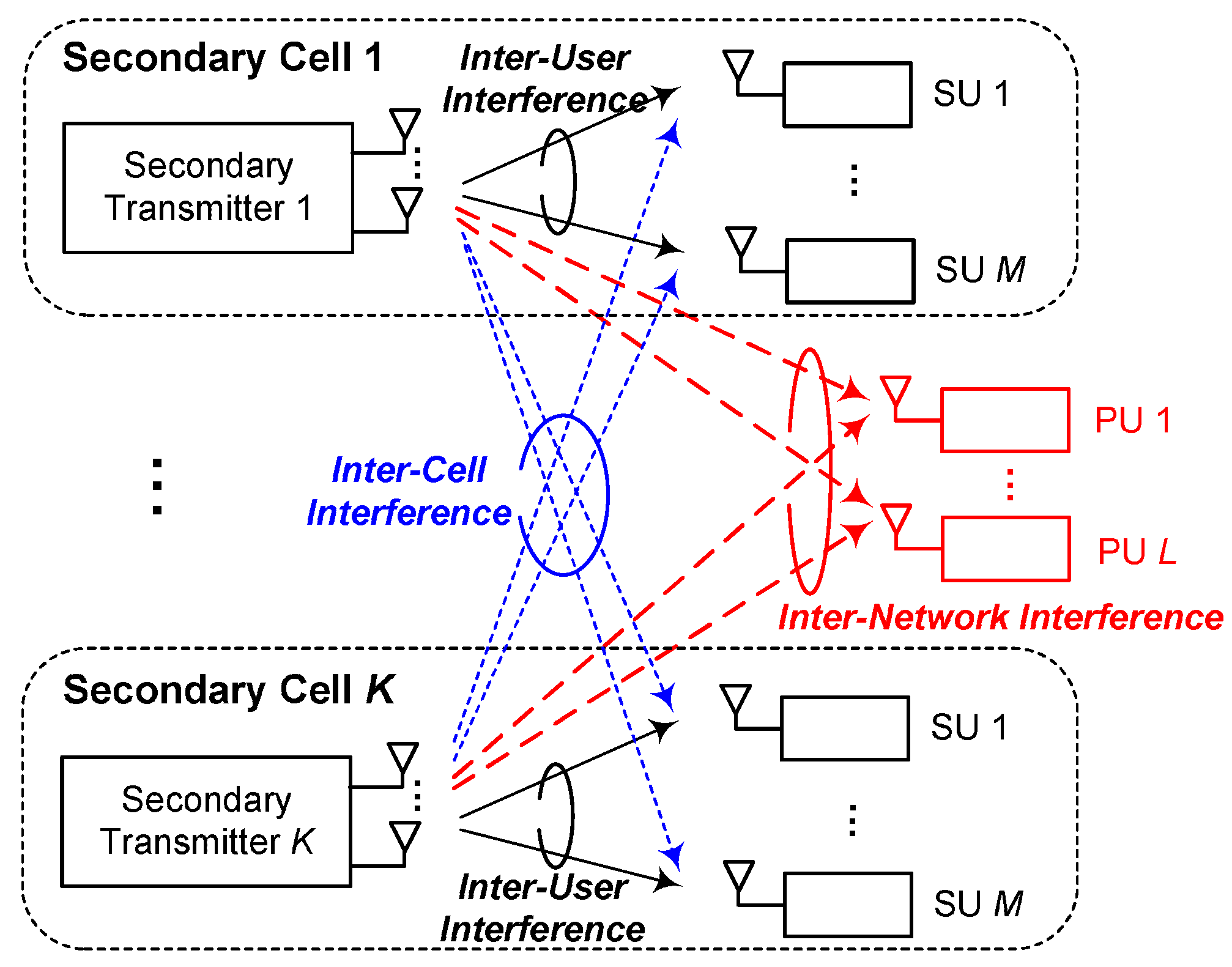
We consider an underlay CR network, as shown in Figure 1, which consists of a primary network and multiple secondary cells. The primary network serves L PUs indexed by . The secondary network consists of K cells. In each secondary cell, an ST with antennas serves M SUs with the inter-network interference constraint to PUs. Let the kth secondary cell be indexed by k, where , and the set of served SUs in the kth cell be denoted by , where the cardinality is . The intersection of all served SUs’ sets is an empty set, i.e., .
Let be the number of feedback bits between ST k and PU l; and is the sum of the feedback bits between ST k and L PUs, . The total number of feedback bits is assumed to be limited to . Furthermore, the total number of feedback bits per SU is limited to , where is the number of feedback bits between ST k and SU m.
The ST needs to know the CDI between the ST and PUs in order to use the beamforming technique for suppressing the inter-network interference from the ST to PUs. In addition, the ST also needs to know the CDI between the ST and SUs in order to use the beamforming technique for suppressing the ICI and IUI in the secondary network. Hence, under the constraint of a limited number of feedback bits, the objective is to determine the number of feedback bits, , between ST k and PU l and the number of feedback bits, , between ST k and SU m.
2.2. Inter-Network, Inter-User, and Inter-Cell Interference
Let be the transmit power of ST k. Assuming the equal power transmission at the ST, the received interference signal from ST k to PU l is given by
where is the path loss factor from ST k to PU l; is the channel vector from ST k to PU l; is the transmit beamforming vector from ST k to SU ; and denotes the transmitted symbol from ST k to SU m.
The instantaneous inter-network interference from ST k to PU l can then be expressed as follows:
There are two kinds of approaches on the inter-network interference constraint from the ST to the PU, the average interference constraint and the peak interference constraint. Many previous studies have considered that the average amount of interference remains below a certain value in order to increase the throughput of the secondary network [18,19]. This paper considers the average interference constraint in the underlay CR network. Hence, the average inter-network interference from ST k to PU l should be below the allowable threshold, , as follows:
The received signal from ST k to SU m is given by
where is the path loss factor from ST k to SU m; is the channel vector from ST k to SU m; and is the noise plus interference signal from the PT to SU m. We approximate to a Gaussian random variable with zero-mean and variance. All the channel elements are assumed to be drawn from independent and identically distributed (i.i.d.) complex Gaussian random variables with zero mean and unit variance. In Equation (4), the first term denotes the desired signal while the second and third terms are respectively the IUI and ICI signal.
The instantaneous SINR of SU m can be expressed as follows:
where and are respectively the IUI and the ICI, as follows:
2.3. Average Inter-Network Interference vs. the Number of Feedback Bits
The obtained CDI at the ST is not perfect because of the quantization error due to the limited feedback bits. We investigate the average inter-network interference according to the number of feedback bits.
Theorem 1.
Given , the average inter-network interference from ST k to PU l is upper bounded by
where we connote for the simplicity of notation.
Proof.
According to the theorem of the random vector quantization (RVQ), we decompose the channel vector as
where = is the amplitude of the quantization error; and is an i.i.d. unit vector. Because we design the transmit beamforming in order to null out the interference given the quantized CDI, we have
The transmit power of an ST is limited in order to meet the average inter-network interference constraint from ST k to PU l. From (3) and (8), the transmit power of ST k is limited as follows:
Given the transmit power of , we rearrange (11) in terms of the number of feedback bits between ST k and PU l, as follows:
The sum of the feedback bits between ST k and PUs, , can then be expressed as follows:
Hence, after rearranging (14) again, we obtain the upper bound of the transmit power of ST k, as follows:
3. Conventional Feedback Bits Allocation for the Sum Rate Maximizing of SUs
The objective of the conventional feedback bits allocation is to maximize the sum rate of SUs given the number feedback bits [17,21,22]. However, while the previous work of [17,21,22] considers a single secondary cell, this paper considers multiple secondary cells in the cooperative CR network. Hence, given the transmit power of STs, we derive the number of feedback bits for each SU to minimize the average rate loss in an underlay CR network with multiple secondary cells. Here, the average rate loss is defined as a difference between the achievable data rate at SU with the perfect CDI and with the limited feedback CDI.
According to the Theorem 1, in the limited feedback system, the average interference power at SU is upper bounded as follows:
Hence, the average rate loss of SU m is bounded as follows:
where and for .
From (18), we can formulate the feedback bits allocation problem that minimizes the average rate loss of SUs as follows:
where denotes the set of positive real numbers for relaxing the integer for into the continuous variables. Because the optimization problem in (19) is a convex function, we can apply the convex optimization technique. In the conventional scheme of [23], the suboptimal feedback bits allocation scheme was investigated for the optimization problem in (19) as follows:
for . Hence, we find that in order to minimize the average rate loss due to the quantization error, the CDI of the link with good channel condition should be more accurate [23].
4. Proposed Feedback Bits Allocation for the GBR Services of SUs
4.1. IUI, ICI, and SU’s SINR
By substituting (20) into (16), the upper bound of the average IUI can be expressed as follows:
where is the upper bound of .
Similarly, from (16), the upper bound of the average ICI is given by
where is the upper bound of .
4.2. Scaling Law of Feedback Bits for GBR Services
For the GBR services of SUs, the secondary cell guarantees the average data rate of each SU, , where is the minimum data rate of the SUs. Under the constraint with , from (23), we have
where is the SINR constraint for satisfying the minimum data rate of SUs. Hence, from (24), the required transmit power of ST k is given by
Additionally, from (15), the transmit power of ST k is bounded because of the average interference constraint at PUs. Hence, from (15) and (25), we obtain
After reformulating (26) in terms of , we obtain
where the scaled feedback bits is derived to guarantee the minimum data rate of SU taking the average inter-network interference constraint at PUs into consideration. Accordingly, to guarantee the minimum data rate of SUs served by ST k, the suboptimal number of feedback bits of ST k is given by
where is obtained from (27).
4.3. Feedback Bits Allocation for Maximizing the Minimum SINR
In the GBR services, we want to increase the minimum SINR in the secondary network in order to increase the data rate of the SU with the worst channel state. Hence, the problem of allocating feedback bits among multiple PUs is to maximize the minimum SINR in the secondary network while keeping the average inter-network interference below a certain value under the limited number of feedback bits for PUs, as follows:
where is the upper bound of the transmit power of ST k from (15) and therefore is the lower bound of of (23).
To provide an explicit solution with a low complexity for the above optimization problem in (29), we consider a suboptimal problem. The equivalent problem in (29) can be expressed as follows:
where a positive constant of is, for ,
Additionally, we have
Hence, for a large positive integer , we can approximate the optimization problem in (29) as follows:
However, for a finite value of , the optimization problem in (36) is suboptimal to that of (29) because of (35).
The optimization problem in (36) is convex since is a constant and the inside term is convex on . The Lagrangian function of (36) is given by
where is the Lagrangian multiplier. Hence, the suboptimal solution of the optimization problem in (36) should meet the Karush-Kuhun-Tucker (KKT) conditions as follows:
where a positive constant of is
Additionally, we have
From (41), we can know that as the value of increases, the CDI should be more accurate in order to increase the minimum data rate of the SUs.
4.4. Feedback Bits Allocation for the Sum Rate Maximization with GBR Services
The proposed scheme aims to increase the sum rate of SUs while guaranteeing the minimum data rate of SUs. Hence, the optimization problem of the feedback bits allocation can be formulated as follows:
where , which is the lower bound of the SINR of SU m, is obtained from (29).
A continuous relaxation technique can by applied to the integer constraint of the number of feedback bits to derive a closed form solution. The constraint of (C1) means the secondary network should guarantee the minimum SINR, , of SUs, in order to provide the GBR services for SUs. However, if the total number of feedback bits, , is not enough, the outage probability may occur. From (27), we can replace the constraint of (C1) with . That is, the number of feedback bits for ST k should be greater than or equal to in order to guarantee the minimum data rate of SU m served by ST k. Moreover, the constraint of (C2) means the total number of feedback bits is limited. We rewrite the integrated optimization problem as follows:
From (43), we find a tradeoff between and . That is, if the total number feedback bits is not enough, i.e., , the outage probability may occur and the minimum data rate of some SUs may not be guaranteed. We aim to reduce the outage probability of the GBR services for SUs while increasing the average sum rate of SUs. To solve the optimization problem of (43), we take a phased approach. First, in order to reduce the outage probability when the total number feedback bits is not enough, we find a pair of (SU m and ST k) with the minimum value of to reduce the required number of feedback bits. Then, we dynamically allocate the remaining feedback bits to STs in order to increase the sum rate of SUs. We develop a heuristic algorithm to allocate feedback bits to PUs, as shown in Algorithm 1.
| Algorithm 1 Proposed feedback bits allocation algorithm |
/* Initialization */
/* Feedback bits allocation for increasing the min SINR */
/* Feedback bits allocation for increasing the sum rate of SUs when */
|
The operation of Algorithm 1 is as follows: First, we set two initialization parameters, and , where is the number of required feedback bits between ST k and PUs to guarantee the minimum data rate for SUs served by ST k; and is the number of temporarily allocated feedback bits between ST k and PUs. From Step 3 to Step 15, we gradually increase the value of by using (27) in order to increase the number of SUs who receive the GBR services. If , the minimum data rate of some SUs may not be guaranteed due to the limitation of the total number of feedback bits; and the algorithm terminates at Step 15. Otherwise, i.e., if , the minimum data rate of all the SUs will be guaranteed. From Step 16 to Step 29, the algorithm allocates the remaining feedback bits, , to STs in order to maximize the average sum rate of SUs. In Algorithm 1, we assume there are two STs, . In line 21 of the algorithm, , which denotes the lower bound of the average data rate of SU m, is given by , where , which is a function of , is obtained from (29).
5. Numerical Results
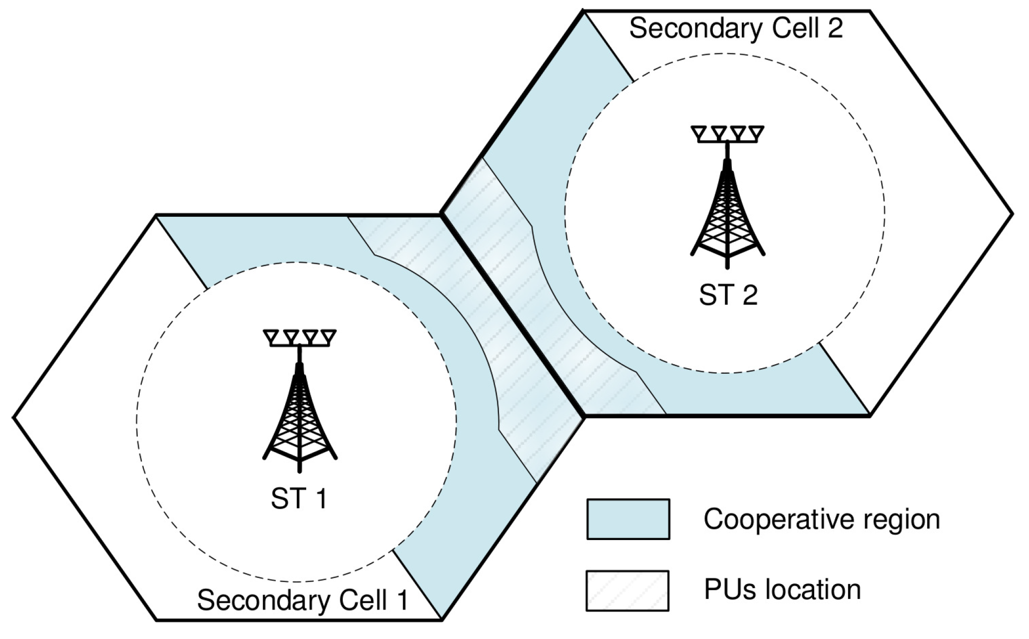
An underlay CR network with , , , and is considered. For all scenarios, is set as dB for , and the average inter-network interference constraint is dB. Additionally, we assume that the path loss coefficient is 3.8 and the standard deviation for large-scale shadowing is dB. We uniformly distributed the location of SUs according to the coordination area of [23]. As shown in Figure 2, all SUs lie in the region , where is the normalized distance from ST k to SU m. Meanwhile, all PUs are distributed in the region , where is the normalized distance from ST k to PU l. The numerical results are obtained by taking an average of 50,000 drop events of PUs and SUs. Here, the drop event means a simulation event that SUs randomly drop in the region and PUs randomly drop in the region ; and we ran simulations.
For the performance comparison, we consider two conventional schemes, the equal feedback bits allocation (EFA) and the adaptive feedback bits allocation (AFA). In the EFA scheme, the number of feedback bits allocated to each SU is the same and the number of feedback bits allocated each PU is also the same, i.e., for and for . In the AFA scheme, the number of feedback bits is adaptively allocated to SUs according to (20) in Section 3 in order to minimize the average rate loss while the number of feedback bits allocated to each PU is the same. Because the previous work of [17] considers a single secondary cell, K = 1, the proposed scheme of [17] belongs to the AFA scheme. Then, in the conventional EFA and AFA schemes, the transmit power of ST k is given by (11).
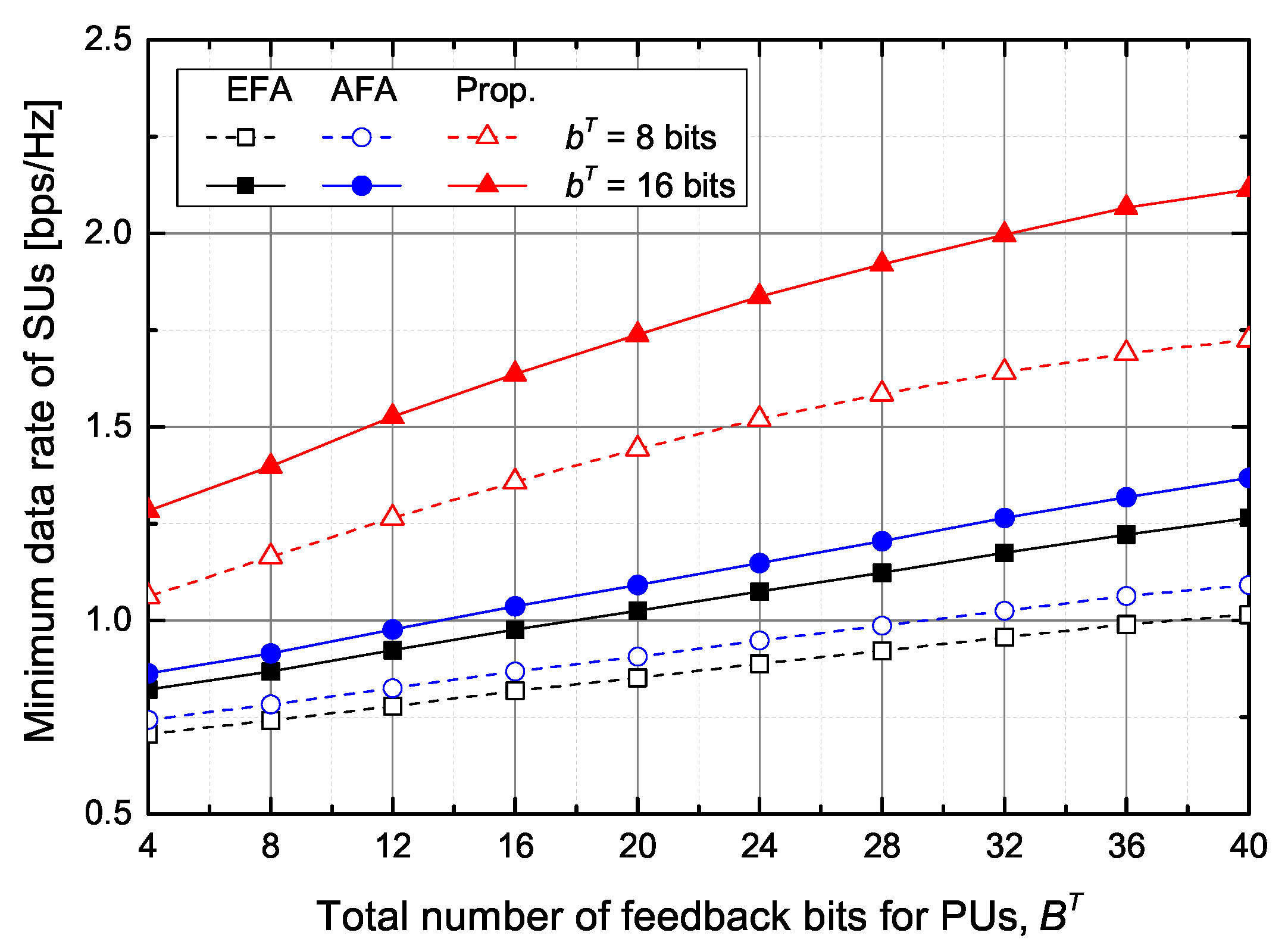
First, from Figure 3, Figure 4, Figure 5 and Figure 6, we evaluate the performance of the feedback bits allocation scheme proposed in Section 4.3, in terms of maximizing the minimum SINR among SUs. Figure 3 shows the supported minimum data rate of SUs according to the number of feedback bits for PUs and SUs under the average inter-network interference constraint at PUs. As the number of feedback bits for PUs, , increases, the ST can increase the transmit power while satisfying the interference constraint. Hence, the minimum data rate of SUs increases with the increase of . The proposed scheme outperforms the conventional EFA and AFA schemes. In particular, when bits and bits, the proposed scheme increases the minimum data rate of SUs by about and , respectively, in comparison with the EFA and AFA schemes. Although the AFA scheme adaptively allocates the feedback bits to SUs, it slightly increases the minimum data rate of SUs compared with the EFA scheme because the conventional AFA scheme does not adaptively allocate the feedback bits to PUs.
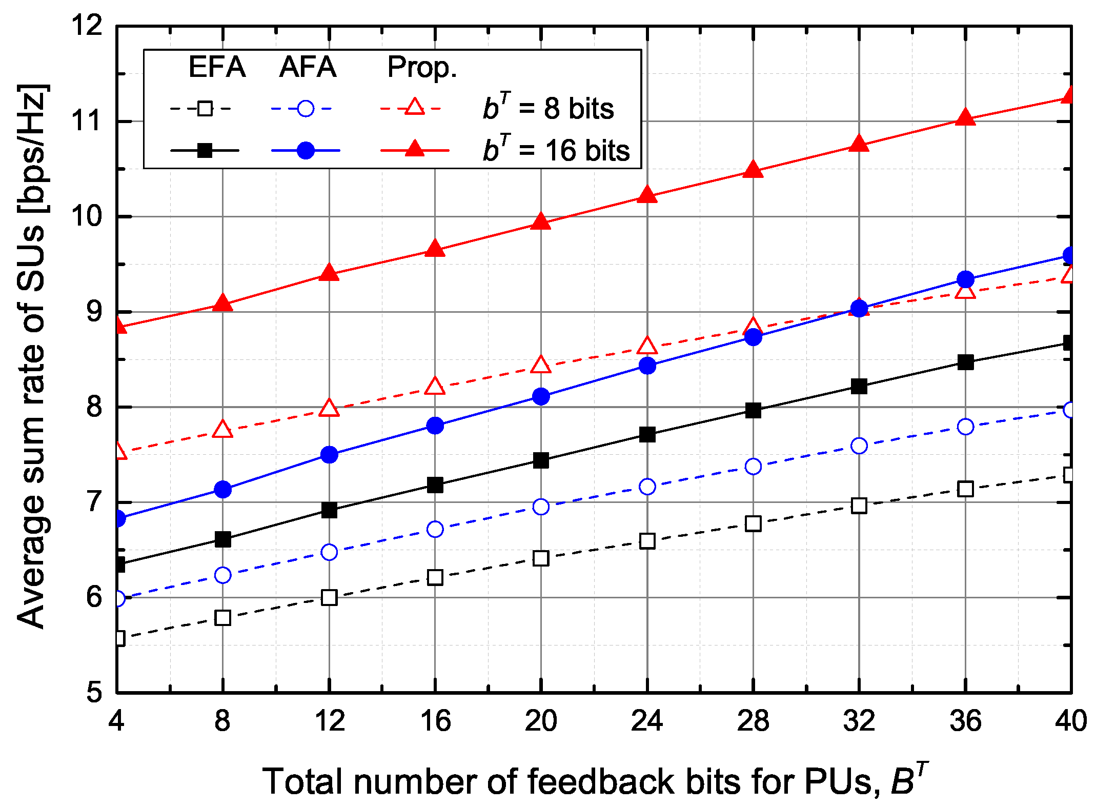
Figure 4 shows the average sum rate of SUs according to the number of feedback bits for PUs and SUs under the average inter-network interference constraint at PUs. As the number of feedback bits for PUs, , increases, the average sum rate of SUs increases thanks to the increase of the transmit power of STs. Similarly, as the number of feedback bits for SUs, , increases, the average sum rate of SUs also increases because IUI and ICI decrease due to more accurate beamforming vectors.
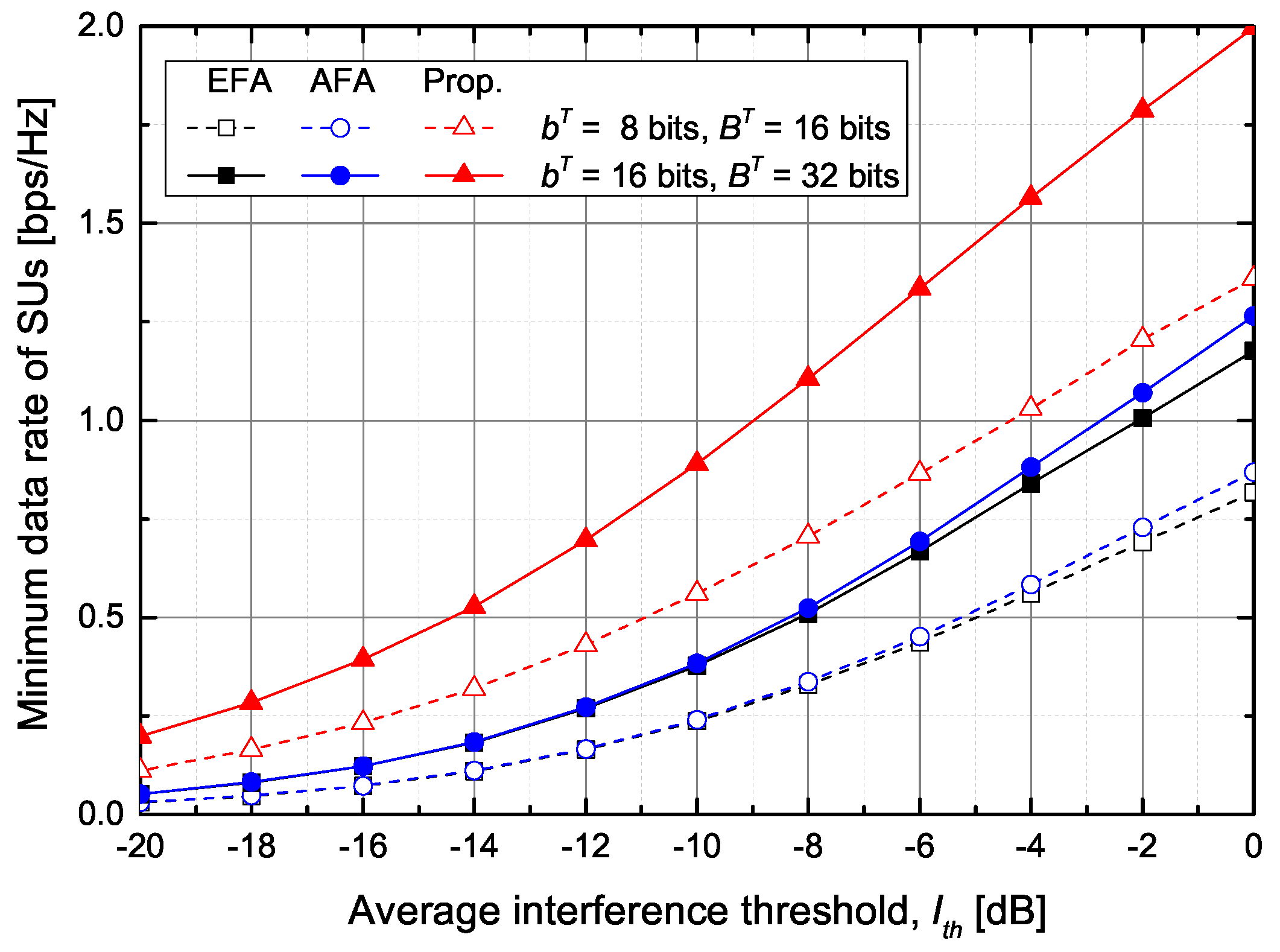
Figure 5 shows the supported minimum data rate of SUs according to the average inter-network interference threshold. As the average interference constraint is relaxed, the minimum data rate of the SUs increases because it increases the allowable transmit power of the ST. The conventional schemes show almost the same minimum data rate of SUs. When bits and bits, the proposed scheme increases the minimum data rate of SUs by about and , respectively, in comparison with the EFA and AFA schemes. In particular, when the minimum data rate is 1 bps/Hz, the average interference from the ST to PUs becomes about dB, dB, and dB in the EFA, AFA, and proposed schemes, respectively.
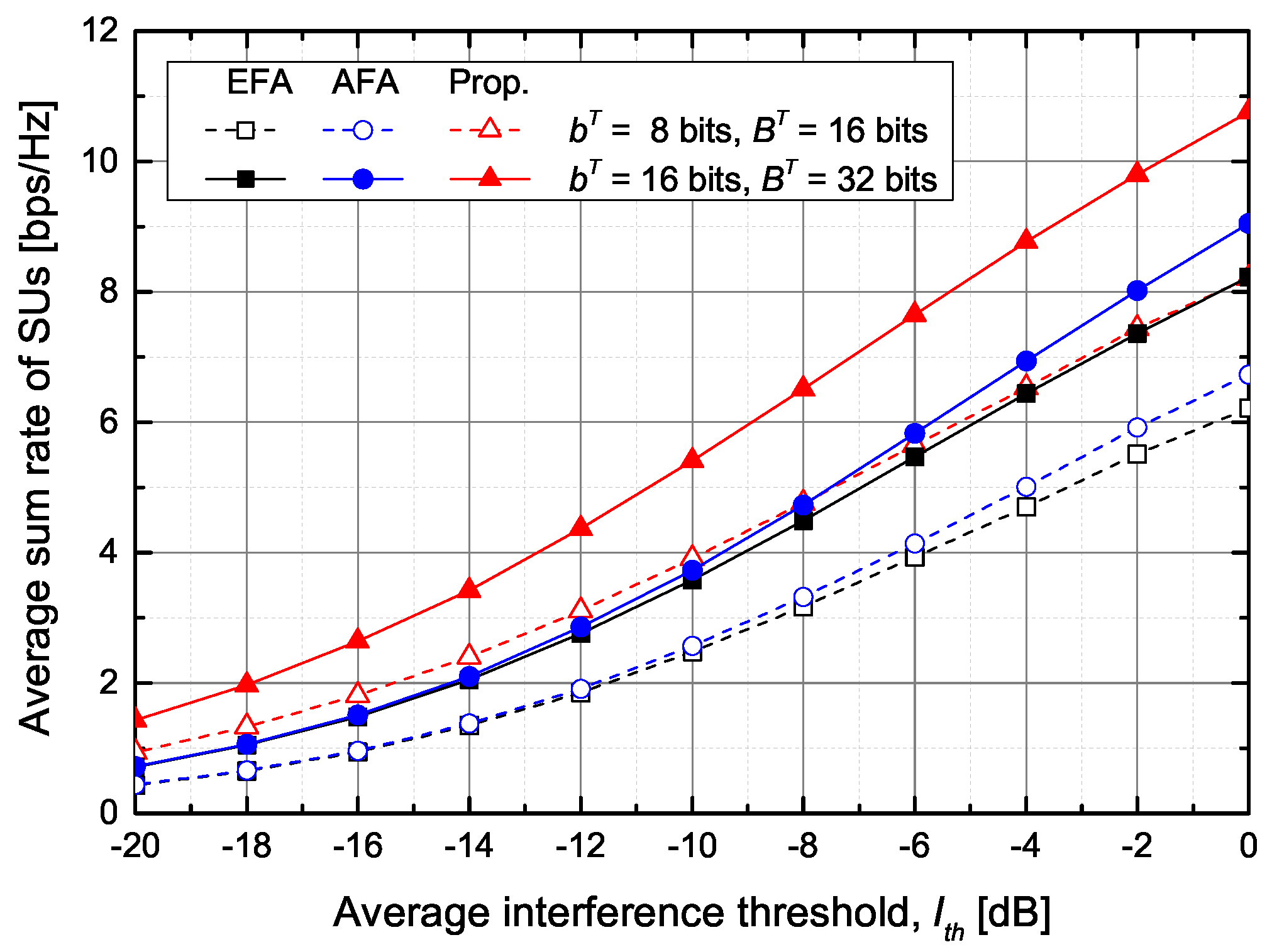
Figure 6 shows the average sum rate of SUs according to the average inter-network interference threshold. The proposed scheme shows that the average sum rate of SUs is higher than that of the conventional schemes. For example, when bits and bits, the proposed scheme improves the average sum rate of SUs by about and , respectively, in comparison with the EFA and AFA schemes.
Although the feedback bits allocation scheme proposed in Section 4.3 increases the minimum data rate of the SUs, it may not guarantee the minimum data rate of SUs because of the limited number of feedback bits. Hence, we need to determine if the number of feedback bits is sufficient to meet the minimum data rate constraint of SUs, by using (28) which is the scaling law of the number of feedback bits.
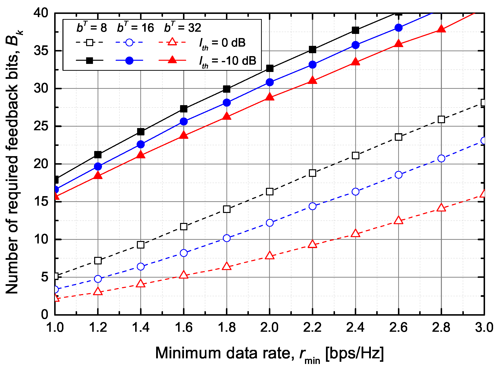
Figure 7 shows the average number of required feedback bits between ST k and PUs to guarantee the minimum data rate of SU when the total number of feedback bits is fixed to bits. As expected, the number of required feedback bits increases as the value of increases. However, even if the value of exceeds the total number of feedback bits, the minimum bit rate of SU m may not be guaranteed. For example, consider dB and bits. If the value of exceeds bps/Hz, the secondary network does not guarantee the minimum data rate even for a single SU. Furthermore, if the sum of exceeds , the secondary network will not meet the minimum data rate of multiple SUs. Accordingly, we aim to reduce the SU’s outage probability while maximizing the sum rate of SUs by using the proposed feedback bits allocation scheme described in Section 4.4.
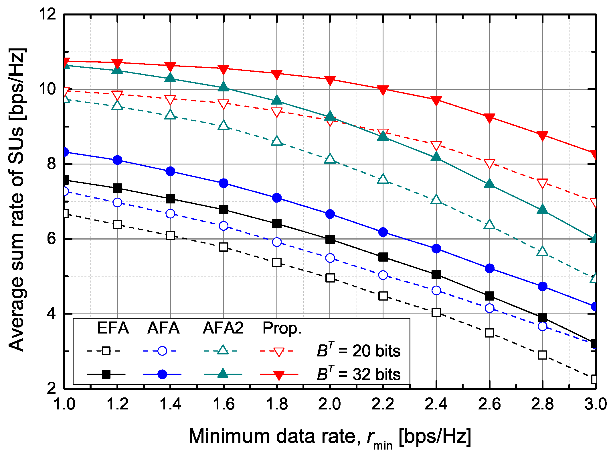
The performance of the proposed scheme is compared with three other schemes, such as the conventional EFA and AFA schemes and the AFA2 scheme. Here, the AFA2 scheme adaptively allocates the feedback bits to PUs according to (12) in Section 2.3. Table 1 summarizes the feedback bits allocation strategy.
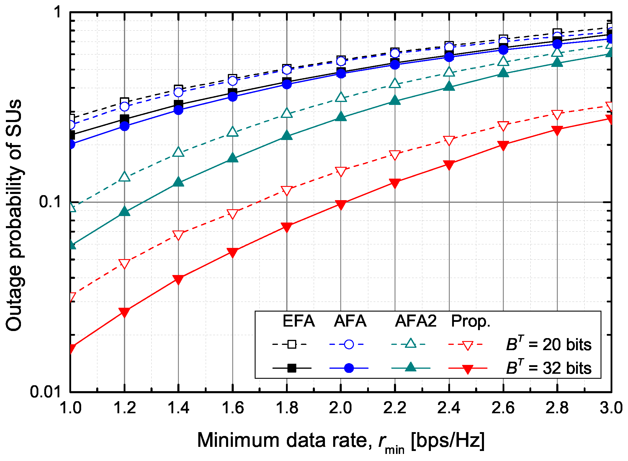
Figure 8 shows the outage probability of SUs according to the required minimum data rate of SUs when dB and bits. The outage probability is calculated by , where is the number of SUs that cannot attain the minimum data rate during simulations, K is the number of secondary cells in the secondary network, and M is the number of SUs in each secondary cell. The EFA and AFA schemes show nearly the same outage probability. That is, if the number of feedback bits allocated to the PUs is the same, it is difficult to guarantee the minimum data rate of SUs because the transmit power of STs cannot be adaptively adjusted. The AFA2 scheme outperforms the EFA and AFA schemes because it dynamically sets the value of under the fixed value of . The proposed scheme shows the best performance. In particular, when bits and the outage probability should be below 10%, the minimum guaranteed data rate is about bps/Hz in the proposed scheme and about bps/Hz in the AFA2 scheme, respectively.
Figure 9 shows the average sum rate of SUs according to the required minimum data rate of SUs when dB and bits. The proposed scheme outperforms the other schemes, the EFA, AFA, and AFA2 schemes. When bps/Hz and bits, the proposed scheme increases the achievable average sum rate of SUs by about , , and , respectively, in comparison with the EFA, AFA, and AFA2 schemes.
6. Conclusions
This paper proposed a feedback bits allocation scheme for the CR network that provides the GBR services for SUs. We first developed the optimization problem that maximizes the minimum data rate of SUs with the fixed number of feedback bits. We found the suboptimal number of feedback bits between STs and PUs as a closed-form by applying a continuous relaxation technique for the integer constraint. On the basis of the closed form of the achievable average data rate of SUs, we derived the required number of feedback bits, between the ST and PUs, needed to guarantee the minimum data rate of SUs. Moreover, we developed the integrated optimization problem that maximizes the sum rate of SUs while reducing the outage probability of SUs. The proposed feedback bits allocation scheme increases the minimum data rate of SUs, without sacrificing the average sum rate of SUs, in comparison with the conventional schemes.
Author Contributions
D.L. has contributed to design the algorithm, perform the simulations, and prepare the manuscript. J.S. has led the research project and supervised the activities as the corresponding author. All authors have read and agreed to the published version of the manuscript.
Funding
This research was supported by the National Research Foundation of Korea (NRF) grant funded by the Korea government (MSIT) (No. 2019R1F1A1058716).
Conflicts of Interest
The authors declare no conflict of interest.
References
- Liang, Y.C.; Chen, K.C.; Li, G.Y.; Mahonen, P. Cognitive radio networking and communications: An overview. IEEE Trans. Veh. Technol. 2011, 60, 3386–3407. [Google Scholar] [CrossRef]
- Kaushik, A.; Sharma, S.K.; Chatzinotas, S.; Ottersten, B.; Jondral, F.K. On the Performance Analysis of Underlay Cognitive Radio Systems: A Deployment Perspective. IEEE Trans. Cogn. Commun. Netw. 2016, 2, 273–287. [Google Scholar] [CrossRef] [Green Version]
- He, Y.; Dey, S. Throughput maximization in cognitive radio under peak interference constraints with limited feedback. IEEE Trans. Veh. Technol. 2012, 61, 1287–1305. [Google Scholar] [CrossRef]
- He, Y.; Dey, S. Power allocation for secondary outage minimization in spectrum sharing networks with limited feedback. IEEE Trans. Commun. 2013, 61, 2648–2663. [Google Scholar]
- Zhang, L.; Liang, Y.C.; Xin, Y. Joint beamforming and power allocation for multiple access channels in cognitive radio networks. IEEE J. Select. Areas Commun. 2008, 26, 38–51. [Google Scholar] [CrossRef]
- Zhang, R.; Gao, F.; Liang, Y.C. Cognitive beamforming made practical: Effective interference channel and learning-throughput tradeoff. IEEE Trans. Commun. 2010, 58, 706–718. [Google Scholar] [CrossRef] [Green Version]
- Choui, S.; Park, H.; Hwang, T. Optimal beamforming and power allocation for sensing-based spectrum sharing in cognitive radio networks. IEEE Trans. Veh. Technol. 2014, 63, 412–417. [Google Scholar] [CrossRef]
- Xu, Y.; Zhao, X.; Liang, Y.C. Robust power control and beamforming in cognitive radio networks: A survey. IEEE Commun. Surveys Tuts. 2015, 17, 1834–1857. [Google Scholar] [CrossRef]
- Chen, X.; Zhang, Z.; Wang, C. Dual QoS driven power allocation in MIMO cognitive network with limited feedbacks. In Proceedings of the IEEE WCNC, Cancun, Mexico, 28–31 March 2011; pp. 1829–1833. [Google Scholar]
- Chen, X.; Zhang, Z.; Yuen, C. Adaptive mode selection in multiuser MISO cognitive networks with limited cooperation and feedback. IEEE Trans. Veh. Technol. 2014, 63, 1622–1632. [Google Scholar] [CrossRef] [Green Version]
- Dahlberg, C.; Liu, Z.; Pradini, A.; Sung, K.W. A techno-economic framework of spectrum combining for indoor capacity provisioning. In Proceedings of the IEEE 24th Annual International Symposium on Personal, Indoor, and Mobile Radio Communications (PIMRC), London, UK, 8–9 September 2013; pp. 2759–2763. [Google Scholar]
- Voicu, A.M.; Simic, L.; Petrova, M. Survey of spectrum sharing for inter-technology coexistence. IEEE Commun. Surveys Tuts. 2018, 21, 1112–1144. [Google Scholar] [CrossRef] [Green Version]
- Wang, Y.; Ren, P.; Du, Q.; Su, Z. Resource allocation and access strategy selection for QoS provisioning in cognitive networks. In Proceedings of the 2012 IEEE International Conference on Communications (ICC), Ottawa, ON, Canada, 10–15 June 2012; pp. 4637–4641. [Google Scholar]
- Wang, Y.; Ren, P.; Gao, F.; Su, Z. A hybrid underlay/overlay transmission mode for cognitive radio networks with statistical quality-of-service provisioning. IEEE Trans. Wireless Commun. 2014, 13, 1482–1498. [Google Scholar] [CrossRef]
- Wang, B.; Zhao, D.; Cai, J. Joint connection admission control and packet scheduling in a cognitive radio network with spectrum underlay. IEEE Trans. Wireless Commun. 2011, 10, 3852–3863. [Google Scholar] [CrossRef]
- Xu, Y.; Zhao, X. Robust power control for multiuser underlay cognitive radio networks under QoS constraints and interference temperature constraints. Wireless Pers. Commun. 2014, 75, 2383–2397. [Google Scholar] [CrossRef]
- Lee, D.; So, J. Cooperative feedback bits allocation and transmit power control in underlay cognitive radio networks. Sensors 2018, 18, 1809. [Google Scholar] [CrossRef] [PubMed] [Green Version]
- Zhang, R. On peak versus average interference power constraints for protecting primary users in cognitive radio networks. IEEE Trans. Wireless Commun. 2009, 8, 2112–2120. [Google Scholar] [CrossRef]
- Wang, C.X.; Hong, X.; Chen, H.H.; Thompson, J. On capacity of cognitive radio networks with average interference power constraints. IEEE Trans. Wireless Commun. 2009, 8, 1620–1625. [Google Scholar] [CrossRef] [Green Version]
- Yoo, T.; Jindal, N.; Goldsmith, A. Multi-antenna downlink channels with limited feedback and user selection. IEEE J. Sel. Areas Commun. 2007, 25, 1478–1491. [Google Scholar] [CrossRef]
- Kibria, M.G.; Yuan, F.; Kojima, F. Feedback bits allocation for interference minimization in cognitive radio communications. IEEE Wireless Commun. Lett. 2016, 5, 104–107. [Google Scholar] [CrossRef] [Green Version]
- Noh, J.H.; Oh, S.J. Beamforming in a multi-user cognitive radio system with partial channel state information. IEEE Trans. Wireless Commun. 2013, 12, 616–625. [Google Scholar] [CrossRef]
- Lee, N.; Shin, W. Adaptive feedback scheme on K-cell MISO interfering broadcast channel with limited feedback. IEEE Trans. Wireless Commun. 2011, 10, 401–406. [Google Scholar] [CrossRef]
Figure 1.
The system model.

Figure 2.
A cooperative region in the simulation.

Figure 3.
The minimum data rate of SUs versus the total number of feedback bits for PUs.

Figure 4.
The average sum rate of SUs versus the total number of feedback bits for PUs.

Figure 5.
The minimum data rate of SUs versus the average inter-network interference threshold.

Figure 6.
The average sum rate of SUs versus the average inter-network interference threshold.

Figure 7.
The average number of required feedback bits between ST k and PUs.

Figure 8.
The outage probability versus the minimum data rate.

Figure 9.
The achievable average sum rate of SUs versus the minimum data rate.


Table 1.
Comparison of the feedback bits allocation strategy.
| Parameter | EFA | AFA [17] | AFA2 | Proposed |
|---|---|---|---|---|
| Fixed | Fixed | Fixed | Adaptive | |
| Fixed | Fixed | Adaptive | Adaptive | |
| Fixed | Adaptive | Adaptive | Adaptive |
© 2020 by the authors. Licensee MDPI, Basel, Switzerland. This article is an open access article distributed under the terms and conditions of the Creative Commons Attribution (CC BY) license (http://creativecommons.org/licenses/by/4.0/).
Share and Cite
MDPI and ACS Style
Lee, D.; So, J. Feedback Bits Allocation for Guaranteed Bit Rate Services in Cooperative Cognitive Radio Networks. Sensors 2020, 20, 469. https://doi.org/10.3390/s20020469
AMA Style
Lee D, So J. Feedback Bits Allocation for Guaranteed Bit Rate Services in Cooperative Cognitive Radio Networks. Sensors. 2020; 20(2):469. https://doi.org/10.3390/s20020469
Chicago/Turabian StyleLee, Deokhui, and Jaewoo So. 2020. "Feedback Bits Allocation for Guaranteed Bit Rate Services in Cooperative Cognitive Radio Networks" Sensors 20, no. 2: 469. https://doi.org/10.3390/s20020469
Note that from the first issue of 2016, this journal uses article numbers instead of page numbers. See further details here.