Efficient Estimator of Rotor Temperature Designing for Electric and Hybrid Powertrain Platform

Division of Development of Electric Powertrain, Renault, Technocentre, 78280 Guyancourt, France
*
Author to whom correspondence should be addressed.
Electronics 2020, 9(7), 1096; https://doi.org/10.3390/electronics9071096
Submission received: 3 June 2020
/
Revised: 26 June 2020
/
Accepted: 1 July 2020
/
Published: 4 July 2020
(This article belongs to the Special Issue Analysis and Optimal Design Method for Electric Machine and Devices)
Abstract
:This paper presents an efficient method of estimation of rotor cage temperature for induction machine design, applied for electric and hybrid vehicles. This factor influences the torque produced by the induction machine with a field-oriented control algorithm. Equipping sensors to measure the temperature of a rotation component is expensive and is not representative of mass production. The approach of estimation of rotor cage temperature is based on the good knowledge of motor parameters and the estimation of the flux of the machine. For an accuracy inductance taking account of the saturation, the no-load test can be performed. The machine flux will be estimated taking account of the voltage drop of the system on the test-bench. The rapid prototyping in a real-time motor control platform will be presented that integrates this estimator of rotor temperature. We finally show the experimental testing results compared to the measurement of the rotor cage on a prototype asynchronous low-cost motor designing for battery electric city cars.
1. Introduction
In the recent 10 years, the development and commercialization of electric vehicles have been dramatic. The battery, the main cost of electric vehicles has seen a significant reduction of its price. In 2018, the global stock of passenger electric cars including BEV (battery electric vehicle) and PHEV (plug-in hybrid electric vehicle) surpassed five million vehicles worldwide after exceeding the one million thresholds in 2015 [1]. Every manufacturer proposes electric vehicles in its product portfolio. Many electric and hybrid vehicle motors currently on the market use permanent magnet synchronous machine (PMSM) like Toyota Prius, Nissan Leaf, Tesla Model 3, BMW i3, or externally excited synchronous motor (EESM) like Renault Fluence, Zoé and others integrate induction machines (IM) like Cadillac CT6, Tesla Model S, X, Y, Renault Twizy, Mercedes-Benz EQC, Audi Q6 [1,2,3]. Because of a severe pollution problem, in Europe, several cities have begun planning to forbid internal combustion engine (ICE) cars [1] in the coming years such as Paris, London, Oxford, Oslo, Hamburg, etc.
The induction motor (IM) is well-known for its low-cost, reliability and simple manufacturing compared to the synchronous machines like permanent magnet synchronous machine (PMSM) and electrically excited synchronous machine (EESM) in traction applications [1,2,3,4,5,6,7,8,9,10]. The lower efficiency and power per volume of the rotor aluminum die-casting cage IM, compared to EESM and PMSM technologies [5,6,7,8,9,10,11], can be solved using copper cage [12,13] and water or oil cooling system [3,4,14,15]. Nevertheless, the torque accuracy of the rotor cage induction machine depends on the rotor temperature, particularly for electric vehicles that request a large torque-speed range. In terms of derating mode in the control system, the winding stator can be protected by silicon temperature sensors directly installed in manufacturing. The rotor is also needed to be protected in order to avoid the demagnetization of the magnet (PMSM) or breakage of the rings and the rotor cage bars (IM) when operating at high temperature and speed. However, the measurement of the temperature of the rotation rotor will require a huge cost that is not representative of mass production. Several studies have been conducted on the estimation of rotor temperatures and cascading motor parameters method [16]. This method needs only the stator resistance but limited for small- and medium-sized industrial applications, establishing a mathematical high-frequency (HF) model for rotor bar [17], using superheterodyne receivers [18] or measuring the reactive power [19]. However, the validations with these proposed methods were realized only compared to the stator temperatures at low-speed operations; no experiments with measurement of rotor temperature were achieved.
This research work focuses on the direct estimator of the rotor temperature of an induction machine designing traction motor for a city battery electric vehicle (BEV). In the first section, the dynamic model of the induction machine, the indirect flux-oriented control algorithm and a novel method of estimation of rotor temperature will be presented. The following section will a describe rapid prototyping control platform. In the last section, the experimental results on a prototype induction machine for electric battery city cars comparing the estimator and the pyrometer will be detailed.
2. Model of Estimator of Rotor Temperature
2.1. Dynamic Model of the Induction Machine
The dynamic model of the induction machine with the synchronous reference reliant to the rotation field is based on nine equations:
- Four equations of flux and current;
- Four equations of flux and voltage;
- One equation of electromagnetic torque.
The equations of flux in the reference dq-axis can be expressed:
The equations of stator voltage in the reference dq-axis are shown in (2):
The equations of rotor voltage in the reference dq-axis are shown in (3):
The electromagnetic torque is expressed by the transient model of the induction machine:
with
- p—number of pole pairs
- Lm—magnetizing inductance
- LIs, LIr—stator and rotor leakage inductances
- Ls, Lr—total inductances of stator and rotor: Ls = Lm + LIs; Lr = Lm + LIr;
- Rs, Rr—resistance of stator and rotor
- ωs—stator electric pulsation
- ωm—rotor mechanical pulsation
- ϕsd, ϕsq—stator flux in the reference dq-axis
- ϕrd, ϕrq—rotor flux in the reference dq-axis
- isd, isq—stator currents in the reference dq-axis
- ird, irq—rotor currents in the reference dq-axis
2.2. Indirect Flux-Oriented Control (IFOC)
Using the control algorithm Indirect Flux-Oriented Control (IFOC) [20] consists of orienting the dq-axis to cancel the quadrature flux component. Therefore, the electromagnetic torque of the induction motor in Equation (4) becomes:
The rotor flux is estimated by:
with is the rotor time constant and s is the Laplace transform variable.
The current isd is obtained by the Park transformation. The electric angle of the Park transformation is the integral of the electric pulsation:
where the pulsation of the motor is a product of the number of pole pairs and the speed of the motor that is measured by a speed sensor.
The pulsation of the slip is calculated as:
The two most influential parameters for the IFOC control of the asynchronous motor are the magnetizing inductance (considering the magnetic saturation state of the machine), and the rotor resistance. The latter is not directly measurable and evolves with the heating of the machine. Without the compensation of the rotor resistance strategy in the motor control, the torque produced will not be close to the demand. Therefore, there are three types of thermal compensation of the rotor resistance that can be envisaged:
- Indirect rotor temperature estimator based on stator winding temperature experimental measurement which is the least accurate;
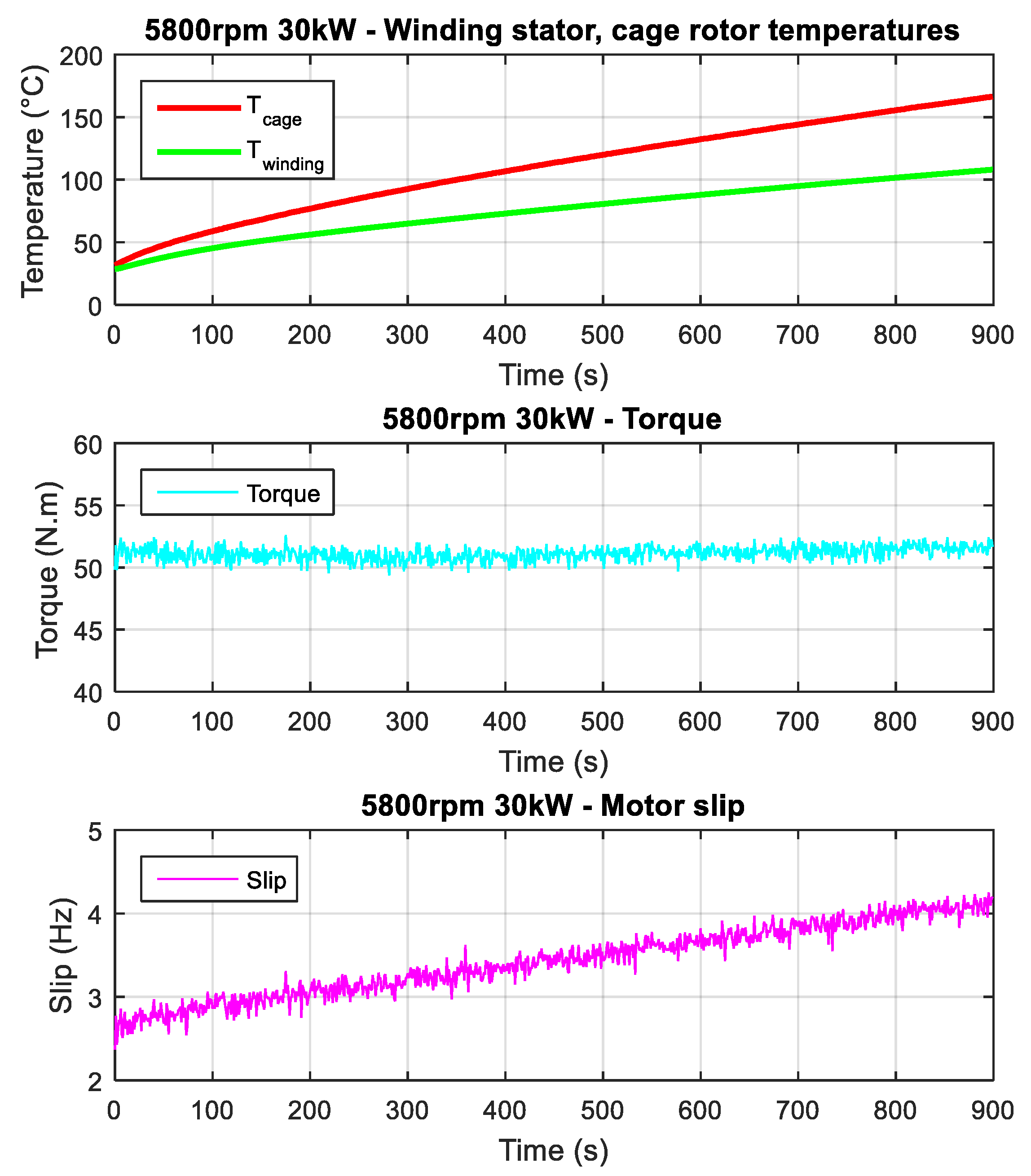
- Direct measurement of the temperature infrared pyrometer (Figure 1). This solution is accurate but expensive in mass production and needs the space to install it;
- Direct rotor temperature estimator via current flow estimation. This needs sophisticated calculations and tuning.
Figure 1 shows the compensation of the rotor resistance thanks to the measurement of the rotor cage temperature using the infrared pyrometer, at 5800 rpm. The torque (or power of 30 kW) is kept constant with 51 N·m demand for 15 min even when the temperatures of the rotor rise from 30 °C to 162 °C. Automatically increasing slip in the control algorithm allows us to ensure this operation.
2.3. Direct Estimator of Rotor Temperature
From (3), the rotor resistance can be expressed in steady state as:
Using the matrix of flux in (1), the rotor flux in d axe is calculated as:
Using (10), (11) and (1), the rotor resistance is now:
were and are given by (2):
Finally, the rotor temperature of the rotor cage is shown as:
with
- —resistance of rotor at 20 °C.
- α—variation coefficient of temperature of the rotor die-casting cage (alu. or copper)
To obtain the correct accuracy of this estimator, it is necessary to correct the voltages vsd and vsq. Indeed, the control voltages are entangled with double errors:
- Phase shift error due to the delay in applying the control voltage to the phases of the machine.
- Amplitude deviation due to idle time and inverter losses (internal voltage drops).
To compensate for these differences, we have identified a model of alteration of the voltage. For the amplitude difference, we used a phase voltage instrumentation (power analyzer) connected to the CAN bus prototyping platform, allowing us to use in the real-time software a reference measurement, and then compare to the estimated voltage using the control variables.
By scanning the operating points at various temperatures, we observed that a simple offset on the 10 V voltage amplitude compensated for amplitude differences quite well.
For the phase shift error, we implemented a calibrated angular correction with respect to the estimated voltage using the control voltage variables. This angular compensation has been provided proportional to the speed since the delay of application of the voltage to the phases by the inverter is a constant time delay related to the switching frequency. The calibration used is a cartography on the regime.
Phase current measurements are also out of phase due to sampling. An angular correction has therefore also been implemented to guarantee the coherence between estimated flows and currents in the calculation of the estimator.
Using the voltage reference measurement, to overcome the amplitude difference, we set this compensation to center the temperature estimation error on a set of operating points.
3. Rapid Control Prototyping Platform
To ensure the development of the motor control, its validation and its development on the test-bench, we used a rapid prototyping solution to implement the Matlab/Simulink schema-block software in real-time. This allows a “model-based design” approach through short development loops, upstream of an industrial development phase.
The principle is to set up a software architecture and control strategies (Figure 2, Figure 3 and Figure 4) using a system design model, and then translate these strategies in real-time on the real system, in test tanks. Throughout development, we maintain the porting of strategies on both the system model and the real-time prototyping. So that we ensure functional justification and prevalidation of software evolutions.
For rapid prototyping, we have adopted the dSpace solution which offers a modular set of control cards integrated into a chassis provided with a power supply, a PHS communication bus and a real-time remote measurement and calibration software, as well as driver libraries in Simulink schema-block format. We use the DS5202 ACMC solution (Alternative Current Motor Control) which offers the possibility of prototyping the entire control, including various PWM variants calculated and realized by a Field Programmable Gate Array (FPGA).
This software prototyping device is itself coupled, for the electronic power part, to an inverter consisting of the following elements:
- A 230 Vac power supply providing the different voltage levels necessary for sensors and drivers: +5 V, +8 V, +15 V, −15 V;
- A module Infineon HP1 250 Arms, 400 V three-phase IGBT inverter module on a cold-water plate;
- A concepts driver board with HW protection stage (minimum dead time, over-current protection (OCP), over-voltage protection (OVP));
- Three-phase current sensors and their conditioning stage (power supply and filtering), voltage interfaces.
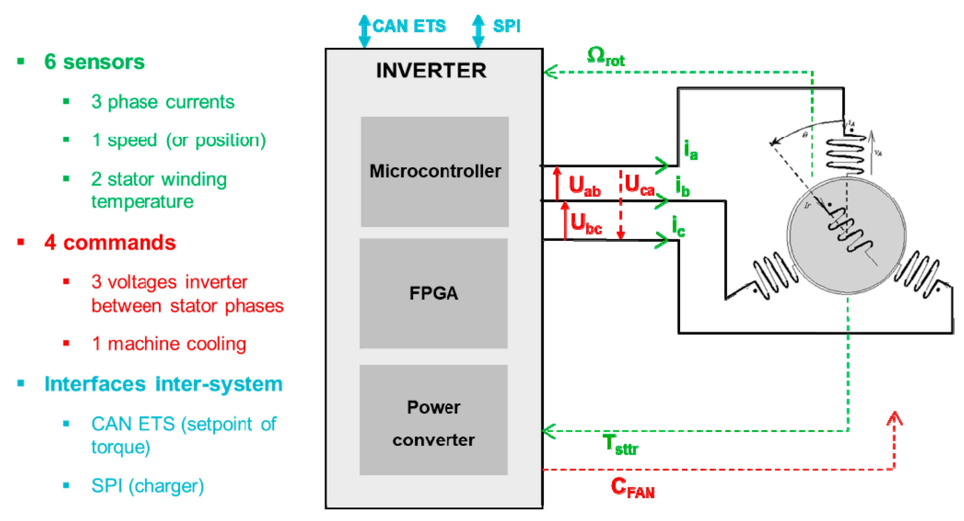
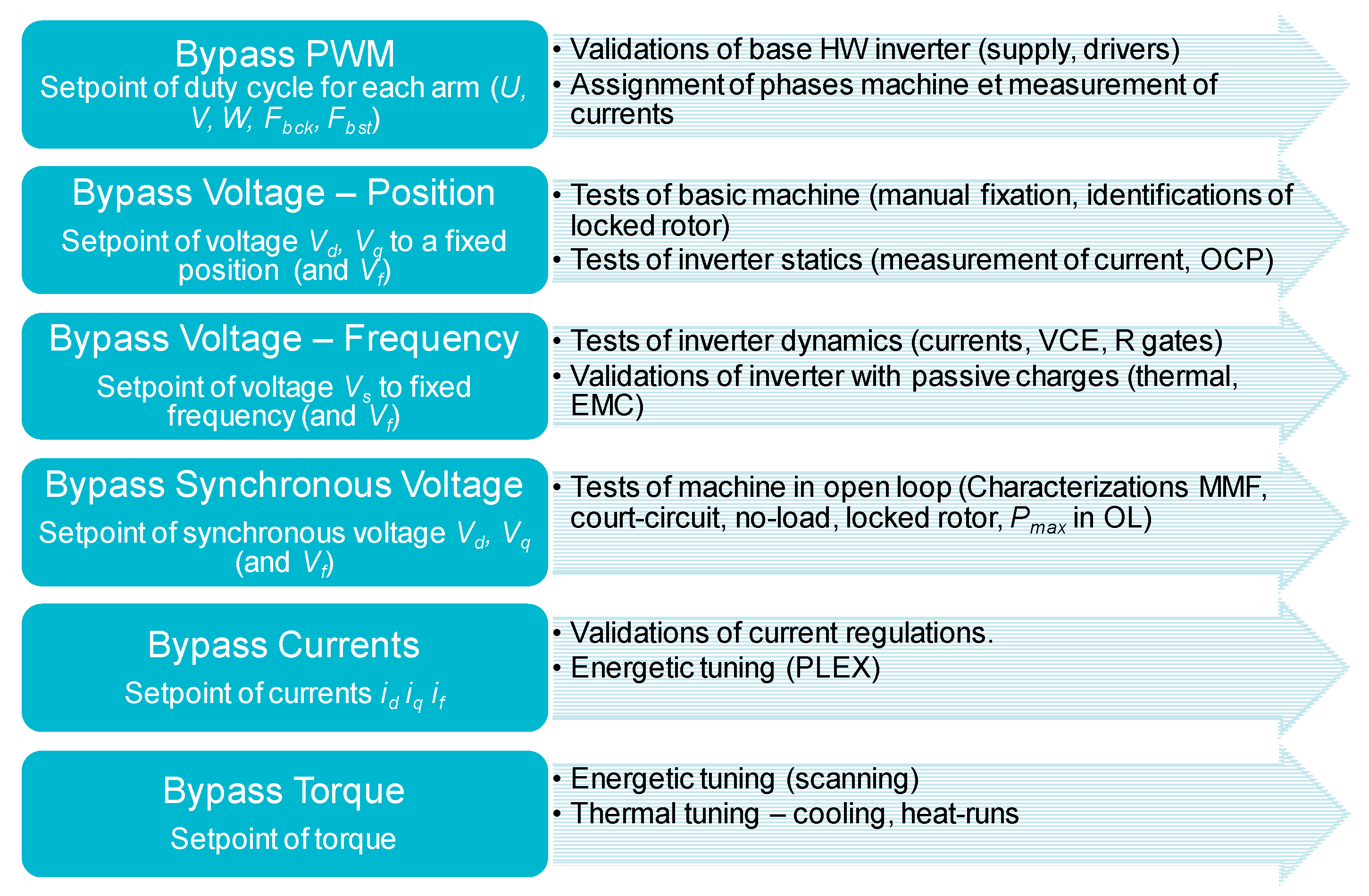
This platform includes the different control modes required for validation and debugging (Figure 3). For each control mode, the necessary interfaces are also defined.
It is then possible to build the architecture of the model-based design platform and build the model of the system.
Integrated into the platform, we have two assembly versions of the software:
- The simulation assembly coupled with the physical design model (environmental load model), the simulated Model in the Loop (MIL).
- The prototyping assembly coupled to the dSpace platform driver interfaces, the computable HIL (Hardware in the Loop) model.
This rapid motor control prototyping platform is focused on being 100% open and editable:
- Interface observing all types of sensors: speed/position sensor, temperature sensor (thermocouple, an infrared sensor for rotor cage instrumentation);
- Modification of the regulation parameters, energy parameters in real-time, no need to flash the inverter (time-saving);
- Soft highly flexible open/modifiable to improve motor control.
4. Experimental Testing Results
4.1. Test-Bench and E-Motor Prototype
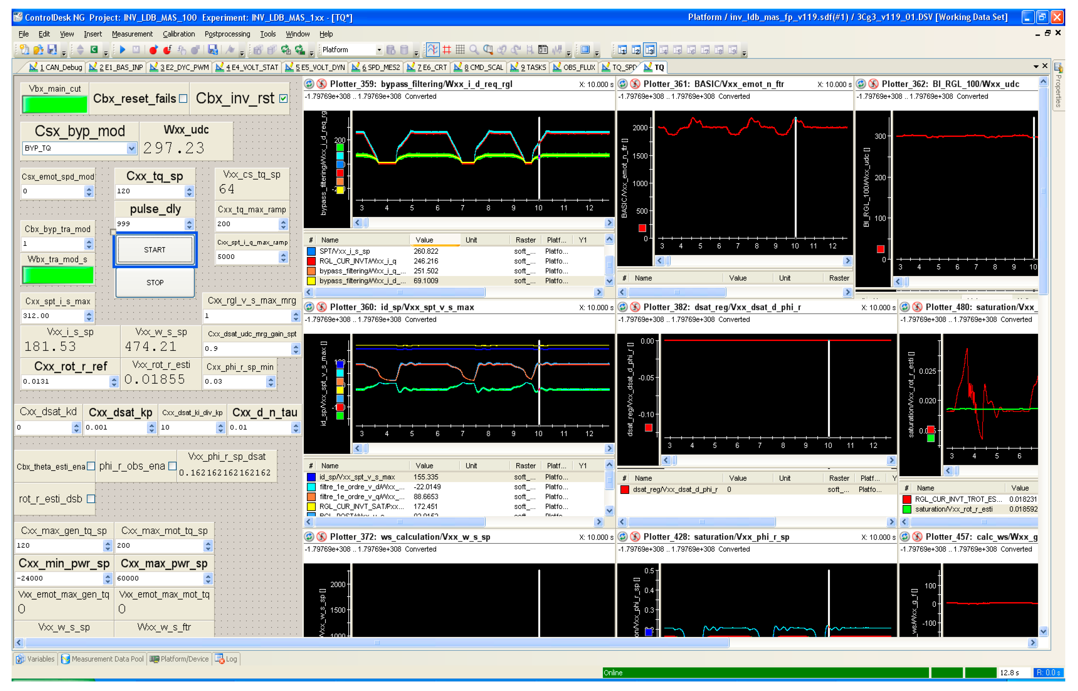
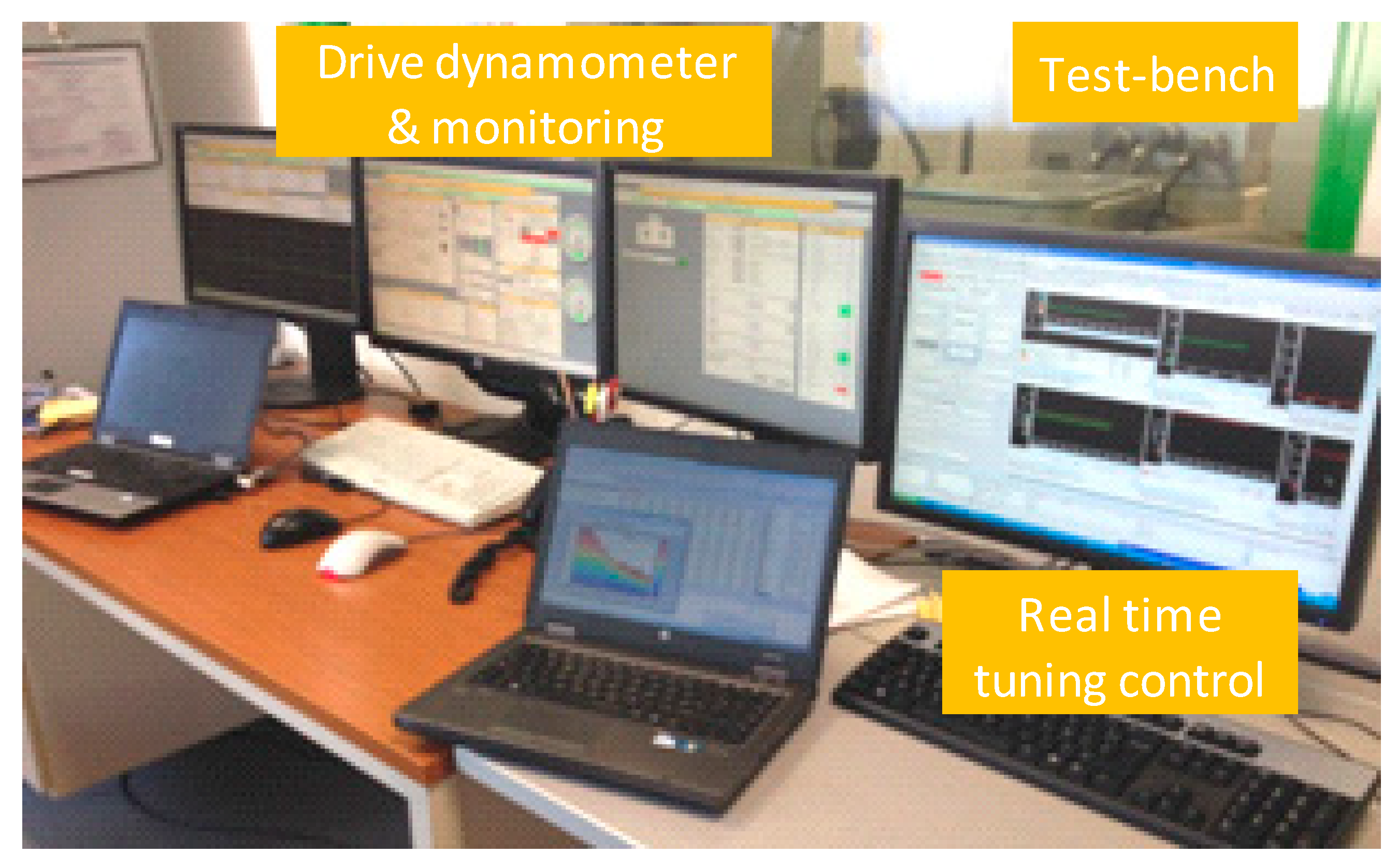
Figure 5 and Figure 6 show the control interface of the rapid prototype platform and the test-bench with installing the prototype. The control area is well protected because of high-speed test-bench with a maximum speed of 15 krpm.
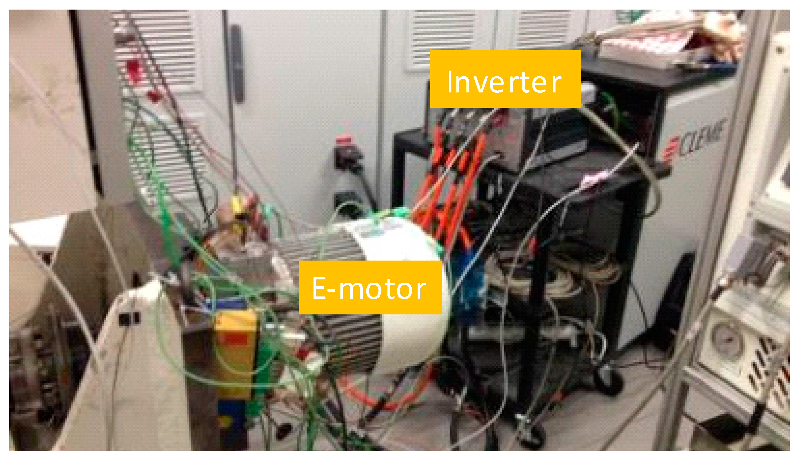
We tested the estimator of rotor cage temperature on a prototype induction machine (Figure 6) with aluminum die-casting rotor cage and totally enclosed fan cooled designed for: 60 kW peak power and 12 krpm top speed, applied for a small battery electric city car [21]. The pyrometer installed on the rear housing is used to measure the online rotor cage temperature.
The motor control calibration is tuned on a test-bench using IFOC model in real-time developed in-house in the Matlab/Simulink environment. No-load and locked rotor tests are performed in order to determine finely the motor parameters (stator and rotor resistances, leakage inductances, magnetizing inductance including the magnetic saturation). The motor control criteria are required in the soft map:
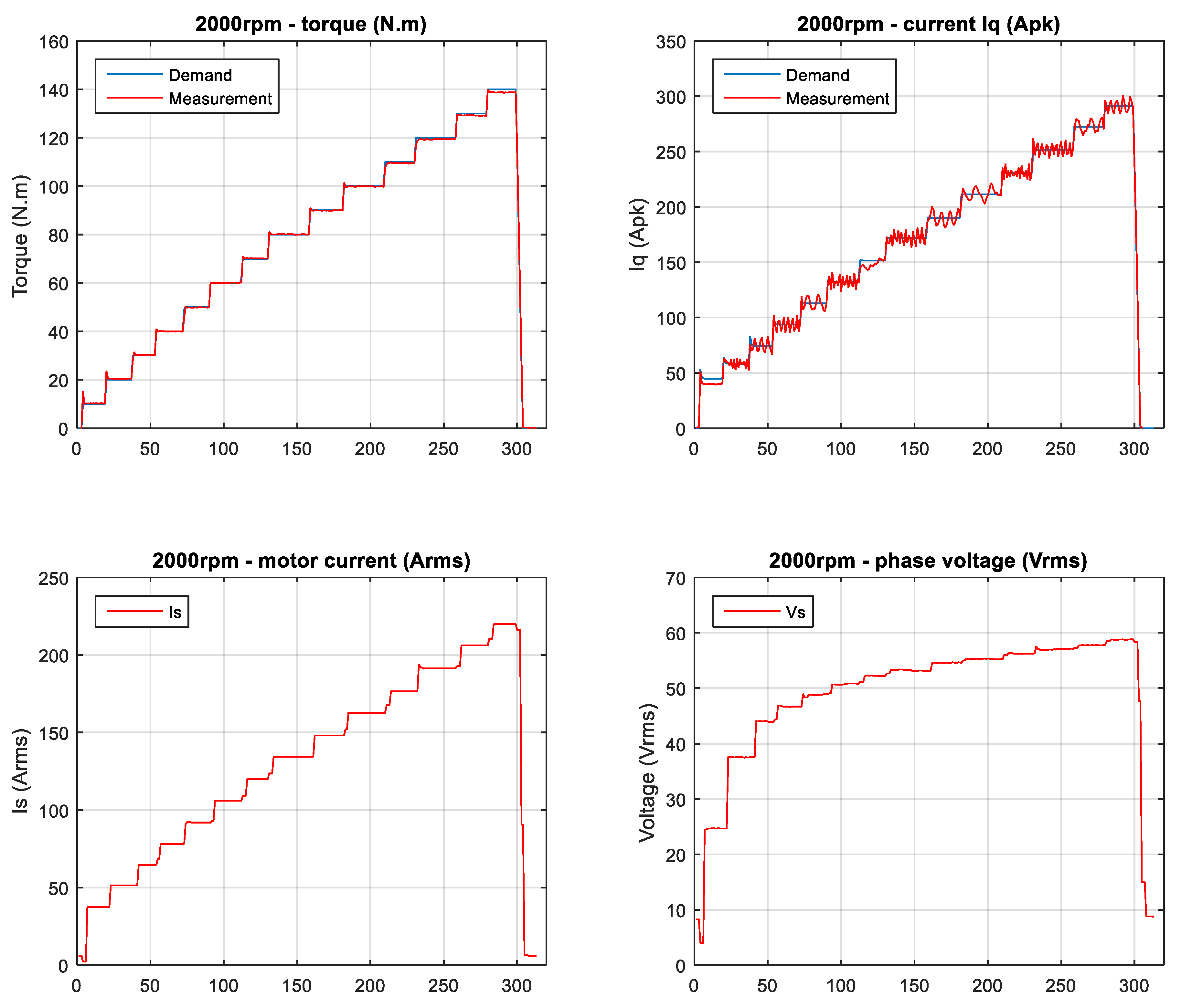
- Ensuring torque responses ± 5% comparing to torque demand in every step, in torque-speed range as shown in Figure 7;
- Including field weakening strategy that consists to reduce automatically the flux when operating at high speed;
- Optimizing the efficiency at every grid point in the whole torque-speed range;
- Taking into account the variation of rotor resistance when motor temperatures increased (Figure 1);
- Realizing the derating mode when the temperature of stator winding or of rotor cage exceeds its limit, by decreasing the power.
4.2. Experimental Results of Estimator of Rotor Temperature
Firstly, the estimator of rotor temperature is experimentally tuned to estimate the right machine flux considering the voltage drop of the whole system on the test-bench (dead time of IGBT, DC/AC cables, connection points).
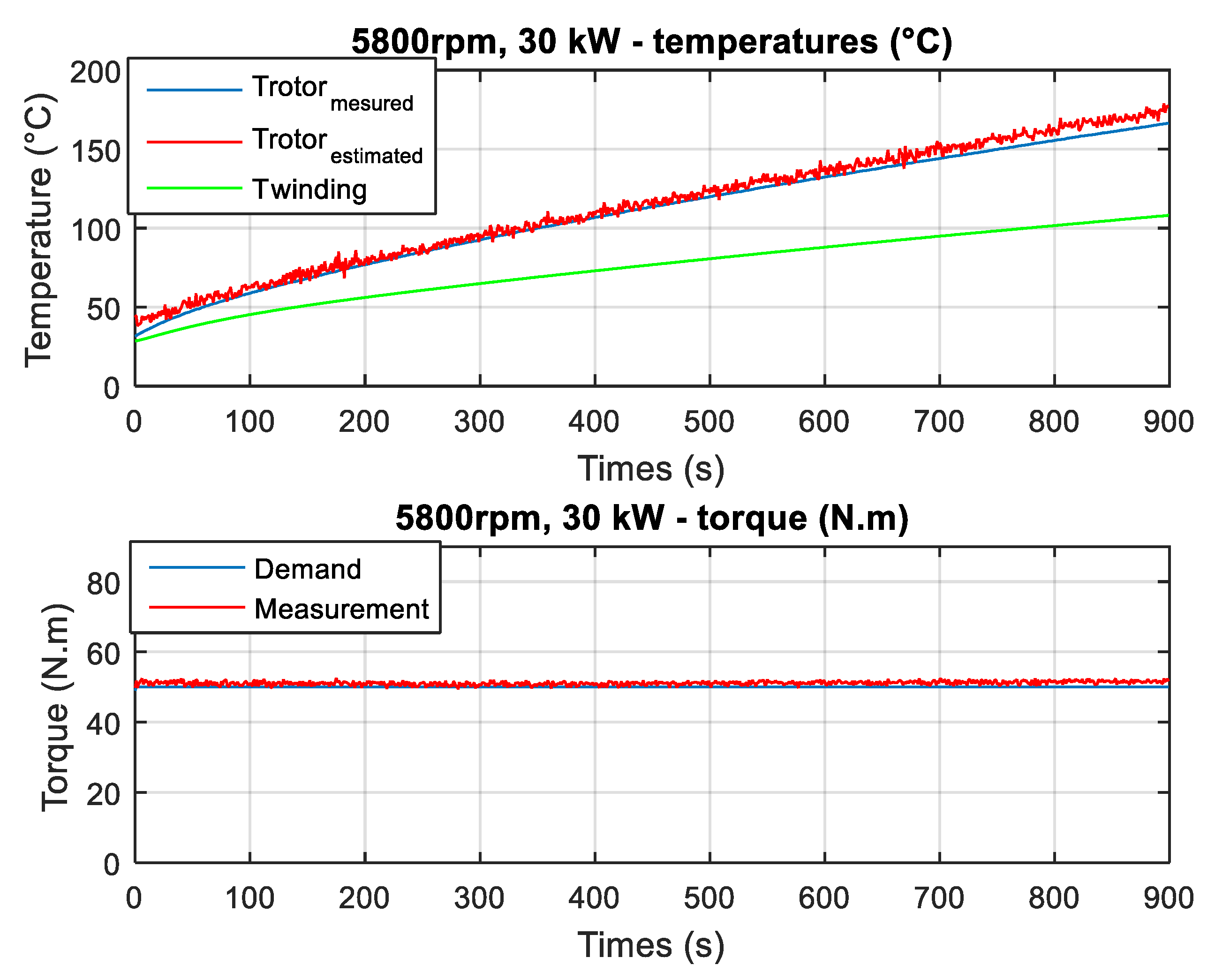
Figure 8 shows a comparison between the results obtained by the measurement of the infrared pyrometer and the ones achieved by the estimator of rotor cage temperature at an operating point of 30 kW at 5800 rpm in field weakening area, during 15 min. The temperature found by the estimator (red color) follows the measured one (blue color). The gap is very close even to a large evolution between 30 °C and 170 °C.
We also note that the temperature of the rotor is higher than the one of stator winding (green color) in this continuous performance for totally enclosed fan cooled (TEFC) with aluminum rotor cage induction machine. The torque produced by the prototype considering the estimator is kept constant in 900 seconds thanks to the compensation of the rotor resistance control technique. This average value is measured of 51.1 N·m, very close (only +2.2%) to the torque demand in Figure 8 (second one).
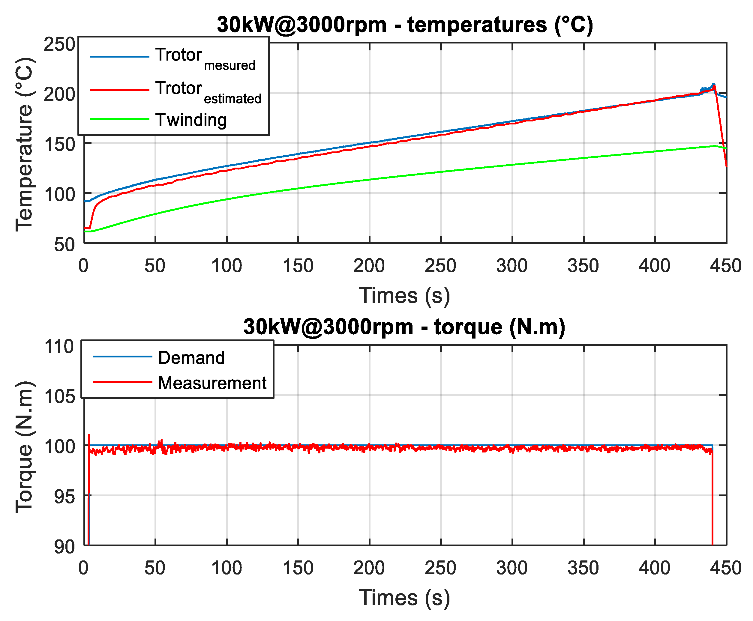
The same things are observed on another operating point at lower speed 3000 rpm and higher torque 100 N·m in Figure 9. The rotor temperature rises between 90 °C and 200 °C for more than 7 min. Even at a quite high initial temperature (90 °C), the estimator quickly follows the real rotor cage temperature. The average torque is measured at 96.6 N·m, only a −3.4% gap compared to the torque request during 450 s in Figure 9 (second). Using TEFC, on equivalent power performance of 30 kW at lower speed of 3000 rpm, the duration is shorter compared to higher speed operating point of 5800 rpm which is higher air flow cooling and lower torque, 51 N·m against 96.6 N·m, consequently fewer joule losses.
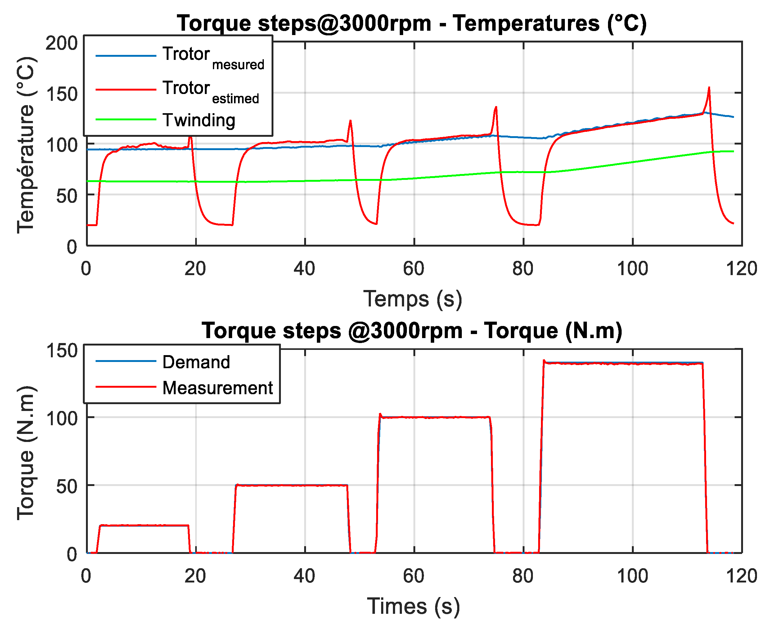
Finally, this estimator is tested on the torque-steps (20/50/100/140) N·m as shown in Figure 10. The torque responses and the temperatures given by the estimator are very close to the demand and heating reality of the machine.
These good results at low speed and high speed in the field weakening region for continuous performances with long durations confirm the effectiveness of the development estimator for rotor cage temperature of induction machine control drive design for electric and hybrid powertrains.
5. Conclusions
In applications of electric and hybrid vehicles, without information on the rotor cage temperature, no protection for the thermomechanical strength of the rotor can be implemented in the control system software. The gap of request torque by the driver’s pedal and produced torque of the induction machine is large and random.
The efficient direct estimator of the rotor cage temperature of the induction machine based on the estimation of machine flux is detailed. This method is suitable for applications of the motor operating in a large torque-speed range. The algorithm is implemented in the rapid control prototyping for electric and hybrid powertrain platforms, developed in-house. The experimental testing results compared to the measurement by a pyrometer on a prototype asynchronous motor of 60 kW peak for city battery electric vehicles in continuous performances of 30 kW at low and high speeds and in torque-steps have validated the proposed method. In any study case, the estimator has found the rotor temperature close to the measurement by pyrometer and the real torque realized by the prototype is very near to the request with a maximum gap of 3.4%. These experimental results and methodology can play a role in the benchmarking for other developments in the community involved in the control design drives and testing of electrical machines.
6. Patents
This research work reported in this manuscript is related to the patent, number of FR3033961B1 [22] written by both authors (T.-V.T. and E.N.).
Author Contributions
This article presents the collective work of both authors (T.-V.T. and E.N.). Both authors have read and agreed to the published version of the manuscript.
Funding
This research work received no external funding.
Conflicts of Interest
The authors declare no conflicts of interest.
Nomenclature
| p | number of pole pairs |
| Lm | magnetizing inductance |
| LIs, LIr | stator and rotor leakage inductances |
| Ls, Lr | total inductances of stator and rotor |
| Rs, Rr | resistance of stator and rotor |
| Rr20 | resistance of rotor at 20 °C |
| ωs | stator electric pulsation |
| ωm | rotor mechanical pulsation |
| ωg | slip pulsation |
| ϕsd, ϕsq | stator flux in the reference dq-axis |
| ϕrd, ϕrq | rotor flux in the reference dq-axis |
| isd, isq | stator currents in the reference dq-axis |
| ird, irq | rotor currents in the reference dq-axis |
| vsd, vsq | stator voltages in the reference dq-axis |
| vrd, vrq | rotor voltages in the reference dq-axis |
| Tem | electromagnetic torque of the motor |
| Ωm | motor speed angular |
| |ϕr|est | estimated rotor flux |
| τr | rotor time constant |
| s | Laplace transform variable |
| θ | electric angle of the Park transformation |
| Trotor | estimated rotor temperature |
| α | variation coefficient of temperature of the rotor die-casting cage (alu. or copper) |
References
- International Energy Agency. Global EV Outlook 2019. Scaling up the Transition to Electric Mobility; Technology Report; OECD Publishing: Paris, France, 20 June 2019. [Google Scholar]
- Un-Noor, F.; Padmanaban, S.; Mihet-Popa, L.; Mollah, M.N.; Hossain, E. A comprehensive study of key electric vehicle (EV) components, technologies, challenges, impacts, and future direction of development. Energies 2017, 10, 1217. [Google Scholar] [CrossRef] [Green Version]
- Doerr, J.; Attensperger, T.; Wittmann, L.; Enzinger, T. The new electric axle drives from Audi. ATZelektron. Worldw. 2018, 13, 16–23. [Google Scholar] [CrossRef]
- Kim, B.; Lee, J.; Jeong, Y.; Kangi, B.; Kim, K.; Kim, Y.; Park, Y. Development of 50 kW traction induction motor for electric vehicle (EV). In Proceedings of the IEEE 2012 Vehicle Power and Propulsion Conference, Seoul, Korea, 9–12 October 2012; pp. 142–147. [Google Scholar]
- Widmer, J.D.; Martin, R.; Kimiabeigi, M. Electric vehicle traction motors without rare earth magnets. Sustain. Mater. Technol. 2015, 3, 7–13. [Google Scholar] [CrossRef] [Green Version]
- Frias, A.; Pellerey, P.; Lebouc, A.K.; Chillet, C.; Lanfranchi, V.; Friedrich, G.; Albert, L.; Humbert, L. Rotor and stator shape optimization of a synchronous machine to reduce iron losses and acoustic noise. In Proceedings of the IEEE 2012 Vehicle Power and Propulsion Conference, Seoul, Korea, 9–12 October 2012; pp. 98–103. [Google Scholar]
- Dorrell, D.G.; Popescu, M.; Evans, L.; Staton, D.A.; Knight, A.M. Comparison of permanent magnet drive motor with a cage induction motor design for a hybrid electric vehicle. IEEE Trans. Ind. Electron. 2012, 59, 3690–3699. [Google Scholar] [CrossRef]
- Pellegrino, G.; Vagati, A.; Boazzo, B.; Guglielmi, P. Comparison of Induction and PM Synchronous Motor Drives for EV Application Including Design Examples. IEEE Trans. Ind. Appl. 2012, 48, 2322–2332. [Google Scholar] [CrossRef] [Green Version]
- Guan, Y.; Zhu, Z.Q.; Afinowi, I.A.A.; Mipo, J.C.; Farah, P. Comparison between induction machine and interior permanent magnet machine for electric vehicle application. COMPEL Int. J. Comput. Math. Electr. Electron. Eng. 2015, 35, 572–585. [Google Scholar] [CrossRef]
- Yang, Z.; Shang, F.; Brown, I.P.; Krishnamurthy, M. Comparative study of interior permanent magnet, induction, and switched reluctance motor drives for EV and HEV applications. IEEE Trans. Transportation Electrific. 2015, 1, 245–254. [Google Scholar] [CrossRef]
- Seo, J.M.; Ro, J.; Rhyu, S.; Jung, I.; Jung, H. Novel hybrid radial and axial flux permanent-magnet machine using integrated windings for high-power density. IEEE Trans. Magn. 2015, 51, 1–4. [Google Scholar] [CrossRef]
- Tang, Y.; Tesla Inc. Induction Motor with Improved Torque Density. U.S. Patent 7741750B1, 30 June 2010. [Google Scholar]
- Ahmed, F.; Kar, N.C. Analysis of end-winding thermal effects in a totally enclosed fan-cooled induction motor with a die cast copper rotor. IEEE Trans. Ind. Appl. 2017, 53, 3098–3109. [Google Scholar] [CrossRef]
- Davin, T.; Pell, J.; Harmand, S.; Yu, R. Experimental study of oil cooling systems for electric motors. Appl. Therm. Eng. 2015, 75, 1–13. [Google Scholar] [CrossRef]
- Assaad, B.; Mikati, K.; Tran, T.V.; Negre, E. Experimental study of oil cooled induction motor for hybrid and electric vehicles. In Proceedings of the 2018 XIII International Conference on Electrical Machines (ICEM), Alexandroupoli, Greece, 3–8 September 2018; pp. 1195–1200. [Google Scholar]
- Gao, Z.; Habetler, T.G.; Harley, R.G.; Colby, R.S. A novel online rotor temperature estimator for induction machines based on a cascading motor parameter estimation scheme. In Proceedings of the 5th IEEE International Symposium on Diagnostics for Electric Machines, Power Electronics and Drives, Vienna, Austria, 7–9 September 2005; pp. 1–6. [Google Scholar]
- Cho, K.-R.; Seok, J.-K. Induction motor rotor temperature estimation based on a high-frequency model of a rotor bar. IEEE Trans. Ind. Appl. 2009, 45, 1267–1275. [Google Scholar]
- Gao, Z.; Colby, R.S.; Turner, L. Induction-motor rotor temperature estimation using superheterodyne receivers. IEEE Trans. Ind. Appl. 2012, 48, 1267–1278. [Google Scholar] [CrossRef]
- Mapelli, F.L.; Tarsitano, D.; Cheli, F. A rotor resistance MRAS estimator for EV induction motor traction drive based on torque and reactive stator power: Simulation and experimental results. In Proceedings of the 2014 International Conference on Electrical Machines (ICEM), Berlin, Germany, 2–5 September 2014; pp. 31–37. [Google Scholar]
- Wang, F.; Zhang, Z.; Mei, X.; Rodríguez, J.; Kennel, R. Advanced control strategies of induction machine: Field oriented control, direct torque control and model predictive control. Energies 2018, 11, 120. [Google Scholar] [CrossRef] [Green Version]
- Tran, T.V.; Negre, E.; Mikati, K.; Pellerey, P.; Assaad, B. Optimal design of TEFC induction machine and experimental prototype testing for city battery electric vehicle. IEEE Trans. Ind. Appl. 2020, 56, 635–643. [Google Scholar] [CrossRef]
- Negre, E.; Tran, T.V. Renault SAS. Gestion d’une Machine Asynchrone de Vehicule Automobile. Patent FR3033961B1, 31 March 2017. [Google Scholar]
Figure 1.
The 30 kW operating point with slip compensation using infrared pyrometer for measurement of rotor cage temperature.
Figure 1.
The 30 kW operating point with slip compensation using infrared pyrometer for measurement of rotor cage temperature.

Figure 2.
Synoptic of the control interfaces.

Figure 3.
Definition of control modes on the platform.

Figure 4.
Interface of rapid control prototyping in real-time at the test-bench.

Figure 5.
Tuning of motor drive in the real-time control platform of the high-speed test-bench.

Figure 6.
Full instrumentation of the prototype of 60 kW, 12 krpm on the high-speed test-bench.

Figure 7.
Torque-step validations in the optimal tuning of the motor control map.

Figure 8.
Comparison of the temperatures found by estimator against pyrometer and torques for 30 kW at 300 Vdc and 5800 rpm.
Figure 8.
Comparison of the temperatures found by estimator against pyrometer and torques for 30 kW at 300 Vdc and 5800 rpm.

Figure 9.
Comparison of temperatures found by estimator against pyrometer and torques at 100 N·m and 3000 rpm.
Figure 9.
Comparison of temperatures found by estimator against pyrometer and torques at 100 N·m and 3000 rpm.

Figure 10.
Comparison of temperatures found by estimator against pyrometer and torques at 3000 rpm and various torque-steps tests.
Figure 10.
Comparison of temperatures found by estimator against pyrometer and torques at 3000 rpm and various torque-steps tests.

© 2020 by the authors. Licensee MDPI, Basel, Switzerland. This article is an open access article distributed under the terms and conditions of the Creative Commons Attribution (CC BY) license (http://creativecommons.org/licenses/by/4.0/).
Share and Cite
MDPI and ACS Style
Tran, T.-V.; Nègre, E. Efficient Estimator of Rotor Temperature Designing for Electric and Hybrid Powertrain Platform. Electronics 2020, 9, 1096. https://doi.org/10.3390/electronics9071096
AMA Style
Tran T-V, Nègre E. Efficient Estimator of Rotor Temperature Designing for Electric and Hybrid Powertrain Platform. Electronics. 2020; 9(7):1096. https://doi.org/10.3390/electronics9071096
Chicago/Turabian StyleTran, Tuan-Vu, and Edouard Nègre. 2020. "Efficient Estimator of Rotor Temperature Designing for Electric and Hybrid Powertrain Platform" Electronics 9, no. 7: 1096. https://doi.org/10.3390/electronics9071096
Note that from the first issue of 2016, this journal uses article numbers instead of page numbers. See further details here.