Precision Engineering ( IF 3.6 ) Pub Date : 2021-05-09 , DOI: 10.1016/j.precisioneng.2021.04.011 Nikolas Theissen , Theodoros Laspas , Stefan Cedergren , Andreas Archenti
|
Machine tool calibration can be employed to optimise tool path trajectories through on- and off-line compensation of anticipated deflections, which result from a process plan, and to assess the machine tools capability to comply with the geometric dimensions and tolerances of a process plan.
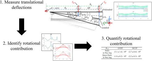
This work presents a measurement for the identification of static and quasi-static rotational stiffness of a rotational joint of 5-axis machining centres. This work shall serve as a basis towards the calibration of translational as well as rotational stiffness of 5-axis machining centres. The novelty of this work lies partly in the measurement procedure for the quasi-static rotational stiffness, which relies on multiple circular trajectories, as well as in the comparison of the static and quasi-static rotational stiffness of machine tools, which is usually identified using finite element approaches. The measurement procedure for the static rotational stiffness consists of inducing a static load directly, from an overhead factory crane, to a single rotational joint and measuring its deflection with both three LVDTsLinear Variable Differential Transformers (LVDTs) as well as three Non-Contact Capacitive Probes (NCCPs). While the measurement for the quasi-static rotational stiffness induces quasi-static loads indirectly from the Loaded Double Ball Bar, with different magnitudes and radii from the axis of rotation, between the tool centre point and the machine tool table. The quasi-static measurement procedure measures the deflection with both three LVDTs as well as three NCCPs while the spindle tracks circular trajectories inscribed by the movement of the rotary axis. The measurement procedures are implemented in two case studies on 5-axis machining centres with significantly different kinematic configurations to be able to highlight and discuss the limitations of the applicability of the method. The presented method works well for machining centres with symmetric and acceptably with asymmetric structures due to the corresponding symmetry of the deflection field.
Finally, the manuscript concludes with a contextualisation of the introduced measurement procedure towards fully calibrated machine tool models, i.e. translation and rotation as well as static and dynamic, which together with customised post-processors and process models, might form the future basis of a stiffness volumetric compensation system.
中文翻译:
识别静态和准静态旋转刚度的测量
可以使用机床校准来通过在线和离线补偿由工艺计划产生的预期挠度来优化刀具路径轨迹,并评估机床的能力以符合工艺计划的几何尺寸和公差。
这项工作提出了一种用于识别5轴加工中心旋转接头的静态和准静态旋转刚度的测量方法。这项工作应作为校准5轴加工中心的平移和旋转刚度的基础。这项工作的新颖性部分在于准静态旋转刚度的测量程序,该程序依赖于多个圆形轨迹,并且还比较了机床的静态和准静态旋转刚度,通常使用有限元方法。静态旋转刚度的测量程序包括直接从高架工厂起重机上产生静载荷,到单个旋转关节,并使用三个LVDT,线性可变差动变压器(LVDT)和三个非接触式电容式探头(NCCP)来测量其挠度。准静态旋转刚度的测量会在刀具中心点和机床工作台之间间接产生来自加载的双球杆的准静态载荷,载荷的大小和半径与旋转轴不同。准静态测量程序使用三个LVDT和三个NCCP来测量挠度,而主轴则跟踪由旋转轴运动引起的圆形轨迹。在具有明显不同运动学配置的5轴加工中心的两个案例研究中实施了测量程序,以便能够突出并讨论该方法适用性的局限性。由于偏转场的相应对称性,所提出的方法对于具有对称结构且可接受地具有非对称结构的加工中心很好地起作用。
最后,该手稿以引入的测量程序针对完全校准的机床模型(即平移和旋转以及静态和动态)为背景进行了总结,这与定制的后处理器和过程模型一起可能构成刚度的未来基础。体积补偿系统。


 京公网安备 11010802027423号